|
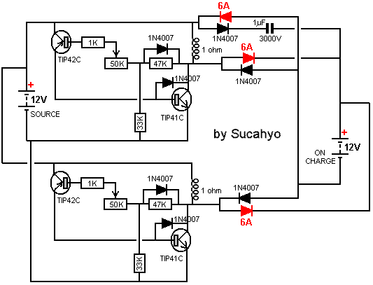
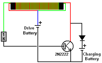
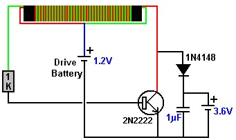
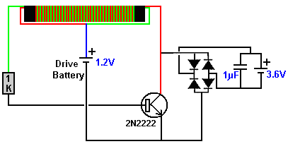
There is nothing magic about free-energy and by “free-energy” I mean something which produces output energy without the need for using a fuel which you have to buy. There are various circuits which I have shown which use the well-known “Joule Thief” circuit as part of the design. These devices have worked well for me. However, in 2014, Sucahyo stated that some people found that pulse-charging batteries for a few times, caused those batteries to then have “surface charge” where the battery voltage rose without there being a corresponding genuine charge inside the battery. That is something which I have never experienced myself but that might be because I didn’t discharge and recharge batteries a sufficient number of times for me to experience the effect. Sucahyo uses this circuit:  which looks rather complicated with two of the transistors connected upside down and protection diodes connected between transistor collector and base. Sucahyo says that he has used this circuit for four years now without experiencing any surface charge effects. My preferred form of Joule thief uses a bi-filar coil of 0.335 mm diameter wire wound on a paper cylinder formed around a pencil and only 100 mm (4 inches) long, as that produces a very cheap and lightweight circuit. As I understand it, the Joule Thief produces a rapid stream of high voltage spikes of very short duration. Those spikes cause the local environment to feed static energy into both the circuit and the circuit’s load device (typically an LED or a battery). While I have never experienced surface charge from a Joule Thief circuit, I tested some old Digimax 2850 mAHr test batteries which had been sitting unused for more than a year. These did indeed show a surface charge effect when load tested. The first test used one battery to drive the circuit and charged three batteries in series using this circuit:  But no matter how long the circuit operated, it would not charge the output battery above 4.0 volts which is 1.33 volts per battery. The load test results were terrible with the voltages at one hourly intervals being 3.93V, 3.89V, 3.84V, 3.82V and 3.79V after only five hours of powering the load. That is ridiculous performance as those batteries managed 22 hours of load powering with the solar panel design. Perhaps the batteries were damaged. So I overcharged them with a main operated charger, reaching 4.26 volts which is 1.42 volts per battery and the hourly load testing results were 4.21, 4.18, 4.16, 4.15, 4.13, 4.12, 4.10, 4.08, 4.07, 4.07, 4.06, 4.05, 4.03, 4.03, 4.02, 4.01, 4.00 (after 17 hours), 3.99, 3.99, 3.98, 3.97, 3.97, 3.96, 3.96, 3.95 after 25 hours and 3.90 after 33 hours. Clearly, there is nothing wrong with the batteries so the effect must be a factor of the charging. Feeding static electricity into a capacitor converts it into normal “hot” electricity, but we want a very simple circuit, so the next step was to add in a 100 volt 1 microfarad capacitor which looks like this:  making the circuit:  With the battery on charge removed, the voltage on the capacitor reaches 22 volts. Charging the same batteries with this circuit reached 4.14 volts and produced load results of 4.09, 4.05, 4.01, 3.98, 3.96, 3.93, 3.90, 3.88, 3.85, 3.83, 3.81 and 3.79 volts after 12 hours which is much better than the 5-hour total previously experienced. However, obviously, something better is needed. The next step is to use a diode bridge of 1N4148 diodes instead of the single diode, giving this circuit:  Without the charging battery connected, this circuit gives 28 volts on the capacitor and the battery charging is good, giving load testing results of 4.18, 4.16, 4.15, 4.13, 4.11, 4.10, 4.08, 4.08, 4.06, 4.05, 4.04, 4.03, 4.02, 4.00, 3.99, 3.98, 3.97, 3.96, 3.95, 3.95, 3.94, 3.94, 3.93, 3.93, and 3.93 volts after powering the load for 24 hours. This seems to be a very satisfactory result for such a minor alteration. If two 1.2V batteries are used to drive the circuit, without a battery on charge, then the voltage on the capacitor reaches 67 volts, but that is not necessary for charging a 12-volt battery. Although the change is slight, the circuit operation is changed considerably. The capacitor does not discharge instantly and so, for some of the time between the sharp Joule Thief pulses, the capacitor supplies extra charging current to the battery on charge. This does not mean that the battery being charged is charged much faster and you can expect that full charging will take several hours. I have not yet tested it, but I would expect that by using two or more of these circuits simultaneously, should increase the rate of charge;  There is no need to restrict the battery on charge to a nominal 3.6 volts in any of these circuits as a single 1.2 volt drive battery can easily charge a 4.8 volt battery or larger. The value of the capacitor has a considerable effect and I suggest a one microfarad capacitor is a good choice. It has been argued that the two additional diodes on each side of the battery being charged are not necessary, although I have shown them to isolate the two circuits from each other. Patrick Kelly http://www.free-energy-info.com http://www.free-energy-devices.com http://www.free-energy-info.tuks.nl |