|
There is nothing magic about free-energy and by “free-energy” I mean something which produces output energy without the need for using a fuel which you have to buy. John Bedini’s designs have been experimented with and developed by a number of enthusiasts. This in no way detracts from fact that the whole system and concepts come from John and I should like to express my sincere thanks to John for his most generous sharing of his systems. Thanks is also due to Ron Pugh of Canada who has kindly agreed for the details of one of his Bedini generators to be presented here. Let me stress again, that if you decide to build and use one of these devices, you do so entirely at your own risk and no responsibility for your actions rests with John Bedini, Ron Pugh or anyone else. Let me stress again that this document is provided for information purposes only and is not a recommendation or encouragement for you to build a similar device. Ron’s device is much more powerful than the average system, having fifteen coil windings and it performs most impressively. Here is a picture of it rotating at high speed:  This is not a toy. It draws significant current and produces substantial charging rates. This is how Ron chose to build his device. The rotor is constructed from aluminium discs which were to hand but he would have chosen aluminium for the rotor if starting from scratch as his experience indicates that it is a very suitable material for the rotor. Aluminium has a highly dampening effect on magnetic fields. The rotor has six magnets inserted in it. These are evenly spaced 60 degrees apart with the North poles all facing outwards. The magnets are normal ceramic types about 22 mm wide, 47 mm long and 10 mm high. Ron uses two of these in each of his six rotor slots. He bought several spare ones and then graded all of them in order of their magnetic strength, which varies a bit from magnet to magnet. Ron did this grading using a gauss meter. An alternative method would have been to use a paper clip about 30 mm in size and measure the distance at which one end of the clip just starts to rise up off the table as the magnet is moved towards it:  Having graded the magnets in order of strength, Ron then took the best twelve and paired them off, placing the weakest and strongest together, the second weakest and the second strongest, and so on. This produced six pairs which have fairly closely matching magnetic strengths. The pairs of magnets were then glued in place in the rotor using super glue:  It is not desirable to recess the magnets though it is possible to place a restraining layer around the circumference of the rotor as the clearance between the magnet faces and the coils is about a quarter of an inch (6 mm) when adjusted for optimum performance. The North poles of the magnets face outwards as shown in the diagram above. If desired, the attachment of the magnets can be strengthened by the addition of blank side plates to the rotor which allows the magnet gluing to be implemented on five of the six faces of the magnet pairs:  The magnets embedded in the outer edge of the rotor are acted on by wound “coils” which act as 1:1 transformers, electromagnets, and pickup coils. There are three of these “coils”, each being about 3 inches long and wound with five strands of #19 AWG (20 SWG) wire of 0.91 mm diameter. The coil formers were made from plastic pipe of 7/8 inch (22 mm) outer diameter which Ron drilled out to an inner diameter of 3/4 inch (19 mm) which gives a wall thickness of 1/16 inch (1.5 mm). The end pieces for the coil formers were made from 1/8 inch (3 mm) PVC which was fixed to the plastic tube using plumbers PVC glue. The coil winding was with the five wires twisted around each other. This was done by clamping the ends of the five wires together at each end to form one 120 foot long bundle. The bundle of wires was then stretched out and kept clear of the ground by passing it through openings in a set of patio chairs. A battery-powered drill was attached to one end and operated until the wires were loosely twisted together. This tends to twist the ends of the wires together to a greater extent near the end of the bundle rather than the middle. So the procedure was repeated, twisting the other end of the bundle. It is worth remarking in passing, that the drill turns in the same direction at each end in order to keep the twists all in the same direction. The twisted bundle of wires is collected on a large-diameter reel and then used to wind one of the coils.  The coils are wound with the end plates attached and drilled ready to screw to their 1/4 inch (6 mm) PVC bases, which are the bolted to the 3/4 inch (18 mm) MDF supporting structure. To help the winding to remain completely even, a piece of paper is placed over each layer of the winding:  The three multi-strand coils produced in this way were then attached to the main surface of the device. There could just as easily have been six coils. The positioning is made so as to create an adjustable gap of about 1/4 inch (6 mm) between the coils and the rotor magnets in order to find the optimum position for magnetic interaction. The magnetic effects are magnified by the core material of the coils. This is made from lengths of oxyacetylene welding wire which is copper coated. The wire is cut to size and coated with clear shellac to prevent energy loss through eddy currents circulating inside the core. The coils are positioned at equal intervals around the rotor and so are 120 degrees apart. The end pieces of the coil formers are bolted to a 1/4 inch (6 mm) PVC base plate which has slotted mounting holes which allow the magnetic gap to be adjusted as shown here:  The three coils have a total of fifteen identical windings. One winding is used to sense when a rotor magnet reaches the coils during its rotation. This will, of course happen six times for each revolution of the rotor as there are six magnets in the rotor. When the trigger winding is activated by the magnet, the electronics powers up all of the remaining fourteen coils with a very sharp, pulse which has a very short rise time and a very short fall time. The sharpness and brevity of this pulse is a critical factor in drawing excess energy in from the environment and will be explained in greater detail later on. The electronic circuitry is mounted on three aluminium heat sinks, each about 100 mm square. Two of these have five BD243C NPN transistors bolted to them and the third one has four BD243C transistors mounted on it. The metal mounting plate of the BD243 transistors acts as its heat sink, which is why they are all bolted to the large aluminium plate. BD243C transistors look like this:  The circuit has been built on the aluminium panels so that the transistors can be bolted directly on to it, and provided with insulating strips mounted on top of it to avoid short circuits to the other components. Standard strip connector blocks have been used to inter-connect the boards which look like this: 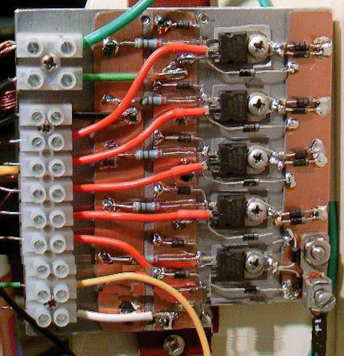 The circuit used with this device is simple but as there are so many components involved, the diagram is split into parts to fit on the page. These diagrams are usually drawn with a common charging wire going to the top of the battery which is being charged. However, it needs to be understood that drawing it that way is just for convenience and better performance is achieved if each charging circuit has its own separate wire going to the charging battery as shown in Section 1 here:  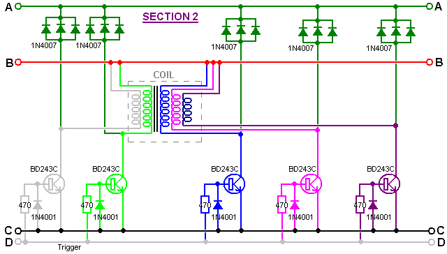  While this looks like a fairly large and complicated circuit, it actually is not. You will notice that there are fourteen identical circuit sections. Each of these is quite simple: 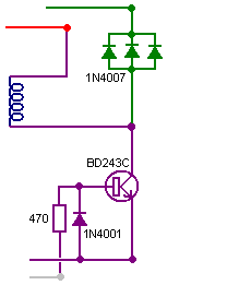 This is a very simple transistor circuit. When the trigger line goes positive (driven by the magnet passing the coil) the transistor is switched on hard, powering the coil which is then effectively connected across the driving battery. The trigger pulse is quite short, so the transistor switches off almost immediately. This is the point at which the circuit operation gets subtle. The coil characteristics are such that this sharp powering pulse and sudden cut-off cause the voltage across the coil to rise very rapidly, dragging the voltage on the collector of the transistor up to several hundred volts. Fortunately, this effect is energy drawn from the environment which is quite unlike conventional electricity, and thankfully, a good deal less damaging to the transistor. This rise in voltage, effectively “turns over” the set of three 1N4007 diodes which then conducts strongly, feeding this excess free-energy into the charging battery. Ron uses three diodes in parallel as they have a better current-carrying capacity and thermal characteristics than a single diode. This is a common practice and any number of diodes can be placed in parallel, with sometimes as many as ten being used. The only other part of the circuit is the section which generates the trigger signal:  When a magnet passes the coil containing the trigger winding, it generates a voltage in the winding. The intensity of the trigger signal is controlled by passing it through an ordinary vehicle 6 watt, 12 volt bulb and then further limiting the current by making it pass through a resistor. To allow some manual control of the level of the trigger signal, the resistor is divided into a fixed resistor and a variable resistor (which many people like to call a “pot”). This variable resistor and the adjustment of the gap between the coils and the rotor are the only adjustments of the device. The bulb has more than one function. When the tuning is correct, the bulb will glow dimly which is a very useful indication of the operation. The trigger circuit then feeds each of the transistor bases via their 470 ohm resistors. Better switching is produced if a Hall-effect sensor is used instead of the Bedini-style switching. This is the starting section of the circuit:  There are various ways of constructing this circuit. Ron shows two different methods. The first is shown above and uses paxolin strips (printed-circuit board material) above the aluminium heat sink to mount the components. Another method which is easy to see, uses thick copper wires held clear of the aluminium, to provide a clean and secure mounting for the components as shown here: 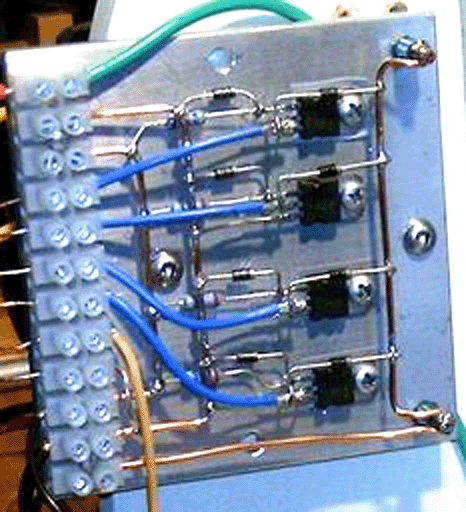 It is important to realise that the collector of a BD243C transistor is internally connected to the heat-sink plate used for the physical mounting of the transistor. As the circuit does not have the collectors of these transistors connected together electrically, they cannot just be bolted to a single heat-sink plate. The above picture might give the wrong impression as it does not show clearly that the metal bolts fastening the transistors in place do not go directly into the aluminium plate, but instead, they fasten into plastic tee-nuts. An alternative, frequently used by the builders of high-powered electronic circuits, is to use mica washers between the transistor and the common heat sink plate, and use plastic fastening bolts or metal bolts with a plastic insulating collar between the fastening and the plate. Mica has the very useful property of conducting heat very well but not conducting electricity. Mica “washers” shaped to the transistor package are available from the suppliers of the transistors. In this instance, it seems clear that heat dissipation is not a problem in this circuit, which in a way is to be expected as the energy being drawn from the environment is frequently called “cold” electricity as it cools components down with increasing current as opposed to heating them up as conventional electricity does. This particular circuit board is mounted at the rear of the unit:  Although the circuit diagram shows a twelve volt drive supply, which is a very common supply voltage, Ron sometimes powers his device with a mains operated Power Supply Unit which shows a power input of a pretty trivial 43 watts. It should be noted that this device operates by pulling in extra power from the environment. That drawing in of power gets disrupted if any attempt is made to loop that environmental power back on itself or driving the unit directly from another battery charged by the unit itself. It may be just possible to power the unit successfully from a previously charged battery if an inverter is used to convert the power to AC and then a step-down transformer and regulated power rectification circuit is used. As the power input is so very low, off-grid operation should be easily possible with a battery and a solar panel. It is not possible to operate a load off the battery under charge during the charging process as this disrupts the energy flow. Some of these circuits recommend that a separate 4 foot long earthing rod be used to earth the negative side of the driving battery, but to date, Ron has not experimented with this. When cutting the wire lengths for coating and pushing into the coil formers, Ron uses a jig to ensure that all of the lengths are identical. This arrangement is shown here: 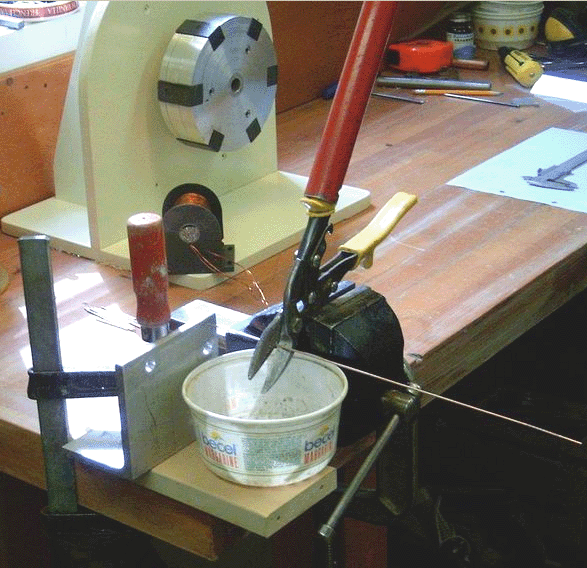 The distance between the shears and the metal angle clamped to the workbench makes each cut length of wire exactly the required size while the plastic container collects the cut pieces ready for coating with clear shellac or clear polyurethane varnish before use in the coil cores. Experience is particularly important when operating a device of this kind. The 100 ohm variable resistor should be a wire-wound type as it has to carry significant current. Initially the variable resistor is set to its minimum value and the power applied. This causes the rotor to start moving. As the rate of spin increases, the variable resistor is gradually increased and a maximum speed will be found with the variable resistor around the middle of its range, i.e. about 50 ohm resistance. Increasing the resistance further causes the speed to reduce. The next step is to turn the variable resistor to its minimum resistance position again. This causes the rotor to leave its previous maximum speed (about 1,700 rpm) and increase the speed again. As the speed starts increasing again, the variable resistor is once again gradually turned, increasing its resistance. This raises the rotor speed to about 3,800 rpm when the variable resistor reaches mid point again. This is probably fast enough for all practical purposes, and at this speed, even the slightest imbalance of the rotor shows up quite markedly. To go any faster than this requires an exceptionally high standard of constructional accuracy. Please remember that the rotor has a large amount of energy stored in it at this speed and so is potentially very dangerous. If the rotor breaks or a magnet comes off it, that stored energy will produce a highly dangerous projectile. That is why it is advisable, although not shown in the above photographs, to construct an enclosure for the rotor. That could be a U-shaped channel between the coils. The channel would then catch and restrain any fragments should anything break loose. If you were to measure the current during this adjustment process, it would be seen to reduce as the rotor speeds up. This looks as if the efficiency of the device is rising. That may be so, but it is not necessarily a good thing in this case where the objective is to produce radiant energy charging of the battery bank. John Bedini has shown that serious charging takes place when the current draw of the device is 3 to 5+ amps at maximum rotor speed and not a miserly 50 mA draw, which can be achieved but which will not produce good charging. The power can be increased by raising the input voltage to 24 volts or even higher - John Bedini operates at 48 volts rather than 12 volts The device can be further tuned by stopping it and adjusting the gap between the coils and the rotor and then repeating the start-up procedure. The optimum adjustment is where the final rotor speed is the highest. Patrick Kelly http://www.free-energy-info.com http://www.free-energy-info.tuks.nl |