|
There is nothing magic about free-energy and by “free-energy” I mean something which produces output energy without the need for using a fuel which you have to buy. There are two ways to run a generator with water as the fuel. The first way is to use some of the electricity output from the generator to convert water into a gas mix and then use that gas mix to power the engine of the generator. 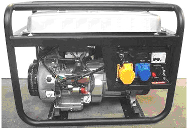 In Broad Outline In order to achieve this objective, we need to feed the engine three things: 1. Air - this is fed in as normal through the existing air filter. 2. HHO gas - how to make this has already been explained in considerable detail. 3. A mist of very small water droplets, sometimes called "cold water fog". Also, we need to make two adjustments to the engine: 1. The spark timing needs to be retarded by about eleven degrees. 2. If there is a "waste" spark, then that needs to be eliminated. To summarise then, a good deal of work needs to be done to achieve this effect: 1. An electrolyser needs to be built or bought, although the required gas production rate is not particularly high. 2. A generator of cold water fog needs to be made or bought. 3. Pipes need to be installed to carry these two items into the engine. 4. The engine timing needs to be retarded. 5. Any waste spark needs to be suppressed. 6. Water tanks are needed for the cold water fog and to keep the electrolyser topped up. 7. Ideally, some form of automatic water refill for these water tanks should be provided so that the generator can run for long periods unattended. If we omit the electrical safety equipment which has already been explained in detail, and omit the HHO gas safety equipment which has already been explained in detail, and skip the automated water supply details and the starting battery, then, a generalised sketch of the overall arrangement looks like this: 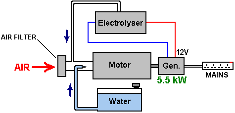 Here, the design has opted to feed the HHO gas into the air system after the air filter (a thing which we normally avoid as it is not helpful for the HHO gas production efficiency, but the first step is to reproduce the existing successful method exactly before seeing if it can be improved further). Also fed into this same area is the cold water fog which is comprised of a very large number of very tiny droplets. The air enters this area as normal, through the existing air filter. This gives us the three necessary components for running the generator engine without using any fossil fuel. Creating the cold water fog There are three different ways to generate the spray of very fine water droplets which are a key feature of the success of this way of running the engine. One way is to use a Venturi tube, which, while it sounds like an impressive device, is actually very simple in construction: 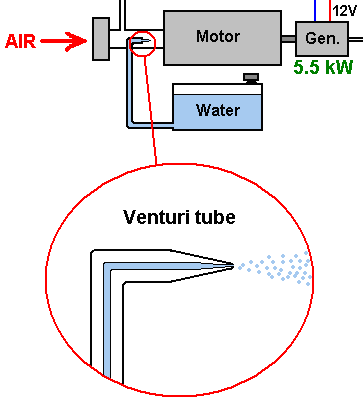 It is just a pipe which tapers to a point and which has a very small nozzle. As the engine draws in the air/HHO mix on it's intake stroke, the mixture rushes past the nozzle of the Venturi tube. This creates an area of lower pressure outside the nozzle and causes water to exit through the nozzle in a spray of very fine droplets. Some perfume spray bottles use this method as it is both cheap and effective. An alternative method of making the cold water fog is to use one or more "pond foggers". These are small ultrasonic devices which are maintained at the optimum operating depth in the water by a float. They produce large amounts of cold water fog which can be fed into the engine like this: 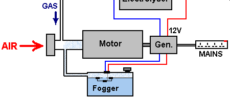 A third method is to use a small carburettor of the type used with model aircraft. This does the same job as a regular engine carburettor, feeding a spray of tiny water droplets into the engine air intake. The physical arrangement of this option depends on the construction of the air filter of the generator being modified. You will notice that the people in the UK who did this, used a small gas tank with an eighteen pounds per square inch pressure release valve. This is not possible with the highest quality of HHO gas as it cannot be compressed that much. However, with a lower grade of HHO which has some water vapour mixed in with it, it is possible to have a gas reservoir with that sort of pressure in it. In this case, except possibly for starting, their gas production rate is probably not high enough to allow much raised pressure inside the tank. Obviously, the gas-pressure switch on the electrolyser and the one on the gas storage tank will have similar operational pressures. Some Safety Features Up to this point, the electrolyser has been shown in bare outline. In practice, it is essential that some safety features are incorporated as shown here: 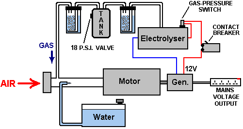 The Reason for Changing the Timing The fuels used with most internal combustion engines are either petrol (gasoline) or diesel. If you are not interested in chemistry, then you are probably not aware of the structure of these fuels. These fuels are called "hydrocarbons" because they are composed of hydrogen and carbon. Carbon has four bonds and so a carbon atom can link to four other atoms to form a molecule. Petrol is a long chain molecule with anything from seven to nine carbon atoms in a chain and is crudely sketched here in a simplified structure:  Diesel has the same structure but with eleven to eighteen carbon atoms in a chain. In a petrol engine, a fine spray of petrol is fed into each cylinder during the intake stroke. Ideally, the fuel should be in vapour form but this is not popular with the oil companies because doing that can give vehicle performances in the 100 to 300 mpg range and that would cut the profits from oil sales. The petrol in the cylinder is compressed during the compression stroke and that reduces its volume and raises its temperature substantially. The air/fuel mix is then hit with a powerful spark and that provides enough energy to start a chemical reaction between the fuel and the air. Because the hydrocarbon chain is such a large molecule, it takes a moment for that chain to break up before the individual atoms combine with the oxygen in the air. The main engine power is produced by the hydrogen atoms combining with oxygen, as that reaction produces a large amount of heat. The carbon atoms are not particularly helpful, forming carbon deposits inside the engine, not to mention some carbon monoxide (CO) and some carbon dioxide (CO2) as well. The key factor here is the slight delay between the spark and the combustion of the fuel. The combustion needs to happen a few degrees after Top Dead Centre when the piston is about to start its downward movement in the power stroke. Because of the delay caused by the hydrocarbon chain breaking down, the spark occurs a few degrees before Top Dead Centre: 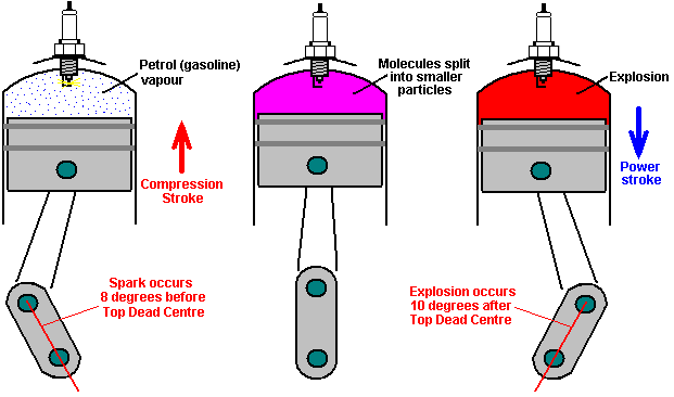 If you were to replace the petrol vapour with HHO gas, then there would be a major problem. This is because HHO gas has very small molecule sizes which do not need any kind of breaking down and which burn instantly. The result would be an explosion which occurs far too soon and which opposes the movement of the rising piston as shown here: 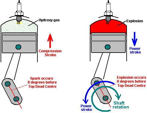 The forces imposed on the piston's connecting rod would be so high that it would be quite liable to break and cause additional engine damage. In the case of our electrical generator, we will not be feeding it a mix of air and HHO gas, but instead, a mix of air, HHO gas and cold water fog. This delays the combustion of the HHO gas by a small amount, but it is still important to have the spark occur after Top Dead Centre, so the ignition of the generator needs to be retarded by eleven degrees. Engine design varies considerably in ways which are not obvious to a quick glance at the engine. The timing of the valves is a big factor here. In the smallest and cheapest engines, the engine design is simplified by not having the spark timing taken off the cam-shaft. Instead, production costs are cut by taking the spark timing off the output shaft. This produces a spark on every revolution of the engine. But, if it is a four-stroke engine, the spark should only occur on the power stroke which is every second revolution of the output shaft. If the fuel is petrol, then this does not matter as the extra spark will occur near the end of the exhaust stroke when only burnt gasses are present in the cylinder. Some people are concerned when they think of HHO gas burning and producing water inside the engine. They think of hydrogen embrittlement and rusting. However, because of the nature of the hydrocarbon fuel already being used, the engine runs primarily on hydrogen anyway and it always has produced water. The water is in the form of very hot vapour or steam and the engine heat dries it out when the engine is stopped. Hydrogen embrittlement does not occur as a result of using a HHO gas booster. Anyway, if we were to delay the spark until after Top Dead Centre as we must, then the situation is quite different as the waste spark will also be delayed by the same amount. With most engines, at this point in time the exhaust valve will have closed and the intake valve opened. Our very flammable gas mix will be being fed into the engine on it's intake stroke. This means that our gas supply system is openly connected to the cylinder through the open intake valve, and so, the waste spark would ignite our gas supply system (as far as the bubbler which would smother the flashback). The situation is shown here: 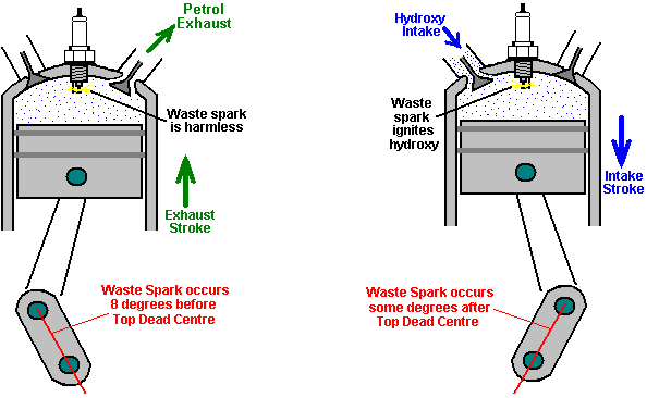 we definitely do not want that to happen, so it is very important that we suppress that additional "waste" spark. So, this leaves us with two engine adjustments: timing delay and waste spark elimination. There are various ways in which these can be done and as each engine design is different, it is difficult to cover every possibility. However, there is a technique which can be used with many engines and which deals with both issues at the same time. Most engines of this type are four-stroke engines with intake and exhaust valves, perhaps something like this: 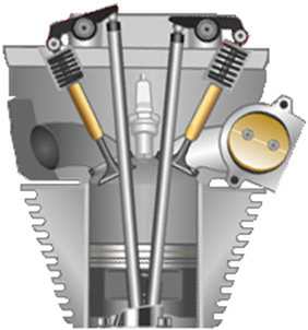 The intake valve (shown on the right in this illustration) is pushed down by a cam shaft, compressing the spring and opening the inlet port. The exact arrangement will be different from one engine design to the next. What is fixed is the movement of the valve itself and that movement only takes place every second revolution. There are various ways of using those movement to eliminate the waste spark and retard the timing. If a switch were mounted so that it opens when the intake valve opens and closes when the intake valve closes, then the switch closure shows when the piston starts upwards on its compression stroke and a simple electronic circuit can then give an adjustable delay before firing the coil which produces the spark. This, of course, involves disconnecting the original electrical circuit so that no waste spark is generated. The current flowing through the switch contacts can be arranged to be so low that there will be no sparking at the contacts when the circuit is broken again. The switch positioning might be like this: 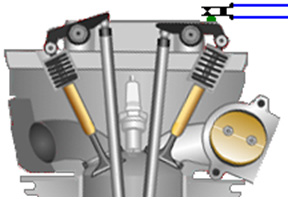 An alternative is to attach a strong permanent magnet to the rocker arm, using epoxy resin, and then position a solid state "Hall-effect" sensor so that it triggers the delay before the spark is generated. If the engine did not have a waste spark, then in theory, the timing mechanism of the engine could be used to retard the spark. However, in practice, the timing mechanism is almost never capable of retarding the spark to the position that is needed for running without fossil fuel, and so, some kind of delay circuit will be needed anyway. The sort of delay circuit needed is called a "monostable" as it has only one stable state. A basic circuit of that type is: 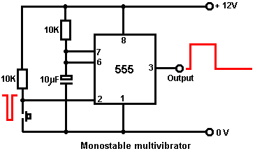 If you are not at all familiar with electronic circuits, then take a look at the beginner's electronics tutorial found in the Appendix as that explains how circuitry works and how to build any simple circuit from scratch. We can use two of these circuits, the first to give the adjustable delay and the second to give a brief pulse to the ignition circuit to generate the spark: 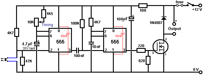 Making the HHO gas When the generator is running, we have a ready supply of electrical energy, coming from a piece of equipment which has been specifically designed to supply large quantities of electricity for any required application. We are not dealing with the spare capacity of some low-grade alternator in a car, but we have substantial electrical power available. Having said that, the electrolysers already described are efficient and it is unlikely that an excessive amount of power would be needed when using one of those designs. Another convenient factor is that this is a stationary application, so the size and weight of the electrolyser is not at all important, and this gives us further flexibility in our choices of dimensions. As this is an application where it is highly likely that the electrolyser will be operated for long periods unattended, an automated water supply system should be provided. The main details of such a system have already been covered, but what has not yet been dealt with is the switching for the water pump. The water pump itself can be an ordinary windscreen-washer pump, and we need some form of switch which operates on the electrolyte level inside the electrolyser. It is sufficient to sense the level in just one of the cells inside the electrolyser as the water usage will be pretty much the same in every cell. If you make the electrolyser in a suitable size or shape, then a simple off-the-shelf miniature float switch can be used. If you prefer, an electronic level sensor can be operated, using two bolts through the side of the electrolyser as the level sensor. A suitable circuit for this simple switching task could be: 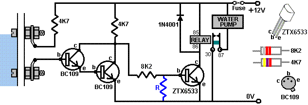 When the electrolyte level inside the electrolyser is in contact with the upper bolt head, the circuit is switched off and the water pump is powered down. The electrolyte has a low resistance to current flow, and so it connects the 4.7K resistor through to the base of the BC109 Darlington pair (as described in the Appendix). This keeps the two transistors switched fully on which keeps the 8.2K resistor connection well below the 0.7 volts needed to switch the ZTX6533 transistor on. If you are concerned about the ZTX6533 transistor being partially on, then resistor "R" could be added, although the prototype did not need one. The value would be about 2K. When the electrolyte level falls below the upper bolt head, the first two transistors switch off, and the ZTX6533 transistor is then powered fully on by the 4.7K resistor and the 8.2K resistor in series, providing the 150 mA needed for the relay to be switched fully on. The circuit draws about 5 mA in it's standby state. The numbers on the relay symbol correspond to the numbers on a typical automotive 12 volt relay. Using two BC109 transistors as the front end allows this circuit to be used with tap water if you wish. However, the water-level control for the water supply to the pond fogger or Venturi tube misting device does not need any form of fancy mechanism. The standard ball-cock valve mechanism which is used with toilets is quite adequate, especially if a floating pond fogger is being used as it maintains its own optimum depth below the surface and so the overall depth is not in any way critical provided, of course, there is sufficient depth for the fogger to float correctly. Starting: When left for any length of time, the gas pressure inside the electrolyser will drop because the nature of the HHO gas alters. This means that there will not be sufficient HHO gas available to start the engine and no more gas will be generated until the engine drives the generator. So, to deal with this situation, a lead-acid car battery is included so that it can be switched in to replace the generator for a brief period before the engine is started. That inclusion gives this overall arrangement: 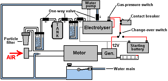 This arrangement is perfectly capable of running a standard generator without the use of any fossil fuel. It should be noted that while no fossil fuel needs to be bought to run this generator system, the electrical output is far from free and is actually quite expensive as there is the purchase cost of the generator, the electrolyser and the minor additional equipment. Also, generators have a definite working life and so will need to be refurbished or replaced. It might also be remarked that if a generator of this type is going to be used in an urban environment, then the addition of sound-reducing baffles and housing would be very desirable. At this point in time I am aware of nine different electric generators which have been adapted to run on water. At least four of these are from different manufacturers. The method of altering the timing and dealing with the waste spark is different from one adaption to the next. One user has altered the spark timing of his generator to after Top Dead Centre by rotating the timing disc to a position not envisaged by the manufacturer. The timing disc is held in place by a locking ("key") bar which fits into a channel cut in the shaft of the engine, matching it to a similar channel cut in the disc. The alteration was achieved by cutting a new channel in the shaft, allowing the timing disc to be positioned further around the shaft, producing the required timing delay. This arrangement also makes the waste spark ineffective and so it can be ignored. While this method requires the cutting of a slot, it does away with the need for any electronics and it is a very simple solution. It has been demonstrated that a gas production rate of around 3 lpm (180 lph) is sufficient to run a generator which produces 5,500 watts of output electrical power. The gain is in running a generator as an internal combustion steam engine and not in the great efficiency of the electrolyser. The facts speak for themselves, with several people scattered around the world, already running generators on water. Many different generator designs have been adapted, typically, by modifying the flywheel, filling in the keyway and cutting another one to give a spark 2 degrees after TDC. Experience has shown that the 6.6 kVA Honda V-twin petrol motor generator and the Vanguard V-twin work very well long-term when adapted to run on water only. Wear and Tear Issues A man who lives in Alaska is very experienced in the use of renewable energy sources and unconventional fuel systems. His experiences are likely to be helpful for anyone who intends to use an electrical generator, whether running on water or on a fossil fuel. He recalls the experiences of a friend: He decided to live off-the-grid because it was going to cost him $20,000 to get connected to the grid and as his house was not that large, he decided to go the alternative route. We designed a system which would use a 4 kW inverter and have an 8 kW Briggs & Stratton generator with a 13 kW surge capacity, for back up. The system has 6 solar panels and a 24 volt battery bank with 400 amp capacity. Having long summer days here in Alaska, the solar panels have more than enough capacity for charging the battery bank on sunny days. However, but when the day is overcast or when it is winter when there are only six hours of sunlight, the battery bank does not get charged fully. At these times, the generator is used to top up the battery bank. American generators normally have either two or four 120-volt outputs each rated at 15 amps, plus one 240-volt output rated at 33 amps. If one of the two 120-volt outputs is used to charge the battery bank, then you get left with just the other 120-volt output for any other power needs during the time when the battery bank is being charged. This is not a satisfactory arrangement as operating with one field at maximum power and the other one lightly loaded or unused, causes a field imbalance in the generator, engine crank imbalance and ring or regulator failure within six months. It also causes noisy running and excessive fuel consumption. Run in this way, providing a 60-amp charge rate, the generator ran hard and loud for two to two and a half hours per day, and running it was costing $350 per month for gasoline. The generator failed after four months. In order to balance the loading on the replacement generator, a 15 kVA step-down transformer costing less than $1000 was purchased so that the 240-volt output could be used to drive 120-volt equipment. A transformer to be used for this needs to have a power-handling capacity which is greater than the surge capacity of the generator. A major advantage is that the generator current is halved for any given level of equipment current drawn because the equipment is running at only half of the generator voltage. Using this transformer made a massive difference, giving a balanced output and providing a 90-amp charging rate for the battery bank as well as having ample power to run other household equipment when the battery bank was being charged. The result was a charge time of just one hour twenty minutes per day, with the generator running quietly and smoothly. The fuel consumption also dropped to just $70 per month which is just one fifth of what it was, covering the cost of the transformer in under four months. This generator has been running now for two years without any problems at all. Selwyn Harris of Australia has kindly agreed to share detailed information on how he performs the conversion of a standard electrical generator to enable it to run on water alone. The generator which he uses as an example for this tutorial is a GX4000i generator: 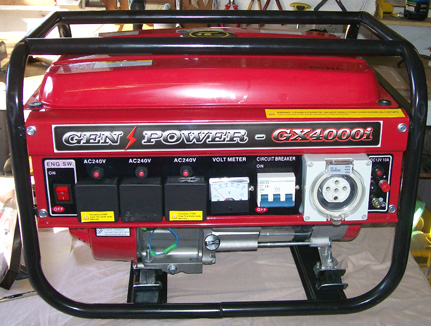 The supplier is AGR Machinery which is an Australian company on eBay which buys up stock from collapsed companies and resells the equipment. The supplier says: GX4000i portable type generators have smoother output power, comparable to public utility sources. Ideal for powering medium loads such as: • Power tools - Both Single & 3 Phase • Game consoles, Digital Cameras • Laptops, Camcorders • Lighting and Microwave Ovens • Drills, Grinders • Resistive Load Kitchen Appliances (i.e. Coffee Maker, Toaster) • Emergency Home Back up power where 240v power is required, Also, these units are significantly quieter than others due to refined engine technology Features: • Commercial Grade Engine: 196 cc 4-stroke, 7 horsepower, overhead camshaft, T.D.I. ignition • Maximum output 4.0 kVA at 240 or 415V AC (Rated output: 2.7 kilowatts) • Quality Heavy-Duty Construction • AVR (Auto Voltage Regulator) • Three 240V and one 415V Protected Outlets • 100% Pure Copper Core • Gearless direct drive • Robust Square frame Design • Easy – Recoil Start • Oil capacity: 0.7 litres • Powder Coated Finish • Light and Compact for easy manoeuvrability (38.5 Kg) • Noise level: 69 dB The first step of the conversion is to remove the fuel tank which is held in place with four bolts: 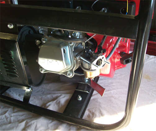 This allows access to the carburettor which is then removed as it will not be used 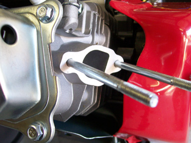 The next step is to construct a pressure-release valve mechanism which will protect the equipment from damage in the unlikely event of a major, sudden rise in pressure caused by the unwanted ignition of the HHO gas mix used to power the generator. For this, parts are purchased from the local hardware store. The brass fittings are a 12mm barrel, a 12mm female T-fitting and a 12mm to 9mm hose reducer as shown here:  The PVC plastic fittings are a ½” to 1-1/4” reducer and a 1-1/4” End Cap, along with the roller ball from an old-fashioned mouse and a relatively weak compression spring to hold the ball in place during normal operation where the gas pressure is low:  These components are then assembled to produce the pressure-release valve: 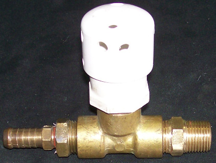 The inside of the flash-arrestor looks like this: 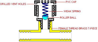 The ball is held in place by the spring allowing the HHO to flow past it, but if a sudden increase in pressure should occur, then the ball is forced upwards, opening a path to the many holes drilled in the plastic fittings: 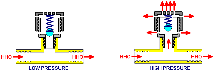 When the gas pressure drops again, the spring pushes the roller ball down to seal off the pressure-release holes. However, Selwyn adds an additional spring-loaded valve to the arrangement. This one is there in case the electrolyser fails to produce a sufficient volume of gas in the event of a sudden increase in demand. This valve is marked as a “vacuum-relief” valve although, strictly speaking, it deals with reduced pressure rather than an actual vacuum. The arrangement is shown below. Please take note of the fact that Selwyn uses the Hogg style of electrolyser and that design has a bubbler built into it, so if you are using some other design of electrolyser, please be very sure to use at least one bubbler between the electrolyser and the engine, in spite of the fact that there is very little chance of the engine misfiring and igniting the HHO gas in the electrolyser. For an engine of this size, an electrolyser which produces 4.5 or 5 lpm of HHO should be adequate. The addition of cold water mist through a Venturi tube as shown, both lowers the engine temperature and increases the engine power as the mist converts instantly to flash-steam when the HHO gas ignites, raising the pressure inside the cylinder and boosting the power output. 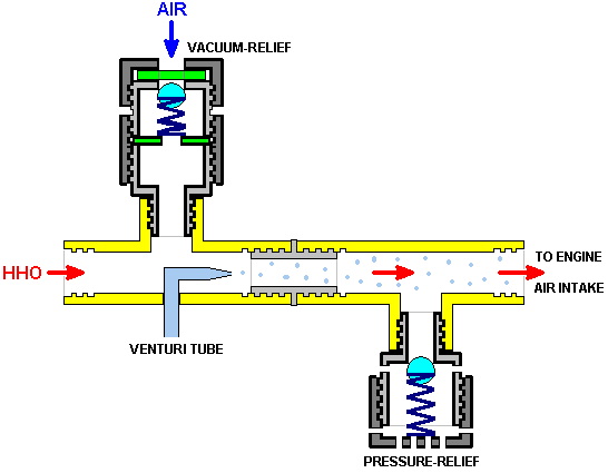 Next, a piece of 1/4" (6 mm) thick aluminium plate is cut and shaped to the size of the carburettor gasket which is not a symmetrical item. This is done by tracing the gasket and transferring it on to the aluminium plate, drilling the holes and then cutting out the outline shape. The edges are then filed to create a nice fit on the engine port. 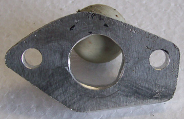 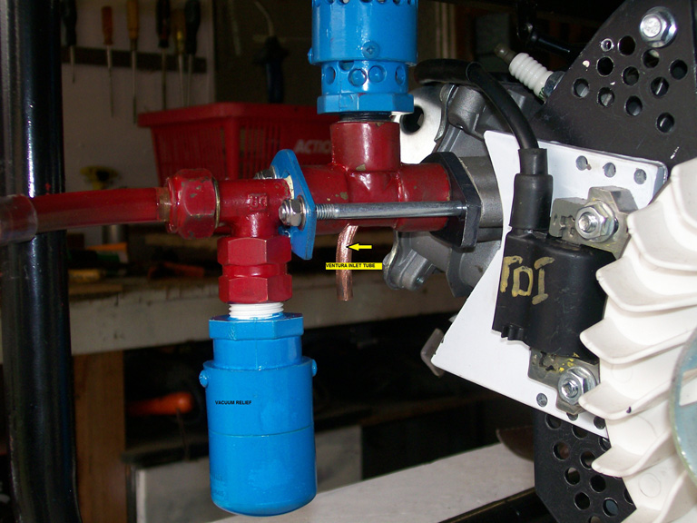 The pipes, backing plate, pressure-relief, vacuum-relief, gaskets, nuts and bolts are then assembled as shown above. Most of the pressure-relief valve components shown in the photograph have been painted, which happens to conceal the different materials being used. At this point an electrolyser of any design which can produce at least 4.5 litres of HHO gas mix per minute is connected to the intake. The electrolyser most often used by Selwyn is the Hogg design disclosed by him earlier. 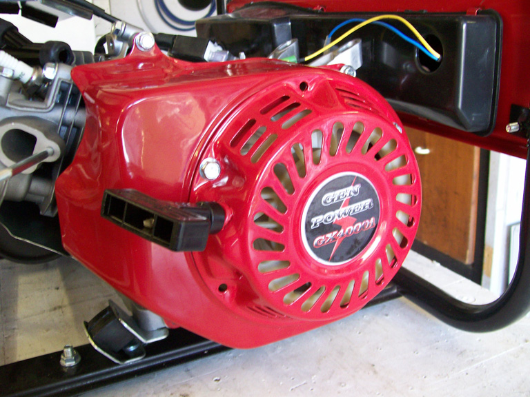 The manual Pull-start and the generator cover are now removed. It is only necessary to remove four of the bolts to take the cover off: 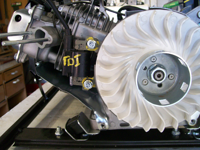 This is the engine with the starter pull and the blower cover removed. At “A” you can see the magnetic pulse type Transistor Discharge Ignition pick-up in it’s original position, bolted in place at 8 degrees before Top Dead Centre. This needs to be removed and an aluminium plate inserted to allow the TDI to be mounted in it’s new position. Because of the new fuel, it is necessary to retard the ignition system. This can be done in one of two ways, neither of which is particularly easy, so you may need the help of an engineering shop. The easiest way is to modify the installed ignition to Top Dead Centre. This is Selwyn’s aluminium TDI adaptor plate which he made from 2mm thick aluminium sheet: 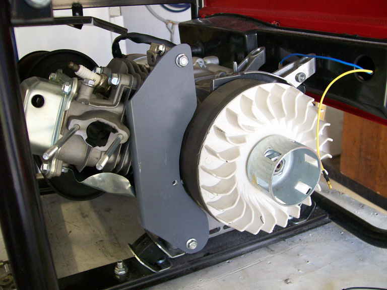 In this picture, the outline of the fuel intake port is obscured due to it having been temporarily blocked off during the construction. The tools required for constructing these components are a drill press and a jig saw fitted with a metal blade. Selwyn used this timing alteration method on his own smaller generator which has run trouble-free for a year. The objective is to delay the ignition spark from 8 degrees before Top Dead Centre to either Top Dead Centre or to 1 degree after TDC. This allows for a good spark on the compression stroke and when the waste spark occurs, the inlet valve has not yet opened and so there is no HHO is in the ignition area. That is to say, the exhaust valve has just closed and the inlet valve has not yet opened. This results in a good compression stroke for the HHO and does not try to send the piston backwards due to premature ignition of the gas mix. The above picture shows the aluminium plate mounted and ready to accept the pick-up. This plate needs to have air holes drilled in it in order to allow cooling air to flow over the engine fins behind it. The TDI adaptor plate looks like this:  And as shown below, the support plate is drilled with the ventilation holes. In this photograph the adaptor plate is just resting on the support plate. Later, when the TDC timing position is established, the adaptor plate will be bolted to it using the three holes top and bottom on the white plate. This locks the timing to that setting and the timing is never changed. In 2010, when adapting a previous generator, an experienced mechanic was asked to establish the TDI plate position and he charged sixty Australian dollars for doing that. 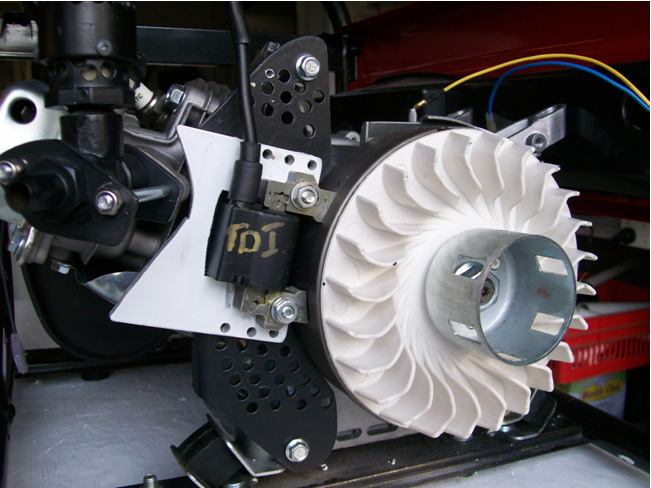 Finally, the covers and the Starter handle need to be bolted back in place. Instead of paying somebody else to set the new spark timing, it is perfectly possible to do that yourself. One effective method is as follows: 1. Mark the casing of the engine in a convenient location as shown in yellow in this photograph: 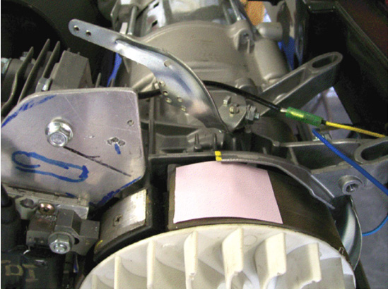 2. Remove the spark plug and insert a long screwdriver until the top of the piston is felt. Manually rotate the engine (clockwise for this generator as can be seen from the curved fan pieces on the flywheel) until the screwdriver is no longer pushed upwards. It may take more than one rotation to find this point accurately. When that point is found, mark the flywheel directly in line with the casing mark which you just made. This marking needs to be very accurate. 3. Continue rotating the flywheel very slowly until the screwdriver starts to go down again and mark that point on the flywheel. Again, this marking needs to be very accurate. 4. Measure the distance along the flywheel between the two flywheel marks which you have just made and then make a larger mark on the flywheel exactly half way between your two marks. If accurately done, this new point is where the flywheel is when the piston is exactly at Top Dead Centre, which is where we want the spark to occur. This marking on Selwyn’s flywheel is like this: 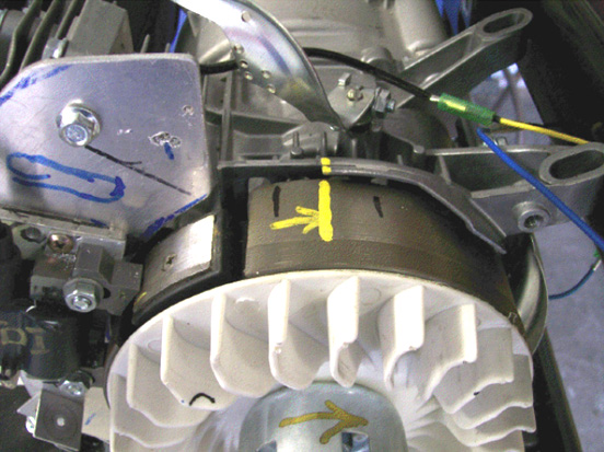 5. Next comes a bit of arithmetic. The diameter of the flywheel is 180 mm which means that it’s circumference is 3.14159 x 180 = 565.5 mm and as there are 360 degrees in each rotation of the flywheel, then the outside edge of the flywheel will move 1.57 mm for each of those degrees. The engine specification states that the spark timing is 8 degrees before Top Dead Centre and we want the spark to occur exactly at TDC, which means that we want 8 x 1.57 = 12.5 mm of the flywheel circumference to have passed by before the spark occurs. 6. To achieve this delay in the spark timing, the TDI needs to be moved 12.5 mm in the direction which the flywheel rotates. You will notice that for this major timing change, the TDI adjustment is very small, only half an inch. 7. When the TDI adjustment has been made, the timing can be checked using an automotive timing light connected to the spark plug lead. The engine can be spun using an electric drill. As the flywheel is spinning fast and the flash of light from the timing light is very short, it makes the flywheel mark appear to be stationary in spite of the fact that it is passing by very rapidly. If the TDI adjustment is correct, then the central mark made on the flywheel will appear to be stationary and exactly aligned with the mark made on the casing. This is exactly what happened when Selwyn’s motor had it’s timing adjusted, but the important factor is to have the spark close to the Top Dead Centre point to make sure that the inlet valve is fully closed before the spark occurs. Two degrees after Top Dead Centre is a popular point for the spark with many of the existing generator conversions which I have been told about, possibly to reduced the loading on the piston’s connecting rod. Here is a photograph of Selwyn’s latest generator conversion having it’s new spark timing checked out: 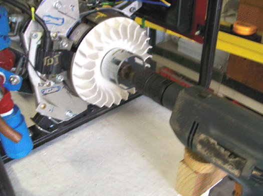 8. Most small petrol engines have the spark timing set between 8 degrees and 10 degrees before Top Dead Centre. If it so happens that you do not know what the timing of your particular generator is, then complete the flywheel marking procedure of step 4 above, but make three additional marks on each side of the TDC mark. Space those marks 1.5 mm apart as they will then make a scale which shows each degree from 3 degrees before TDC to 3 degrees after TDC. When the timing light is used, it then shows exactly where the spark occurs and if the engine had an original spark timing which was not 8 degrees before TDC, then the scale shows immediately how much further the TDI needs to be moved to set the spark exactly where you want it to occur. The Cold Water Mist. Getting the fine droplets of water into the engine can be done two different ways. The first way is to use a Venturi tube which generates a fine spray of droplets when air moves rapidly past a small water-filled hole. You may not have noticed, but this method has been used extensively in perfume sprays and it is very effective. Selwyn describes how he constructs a Venturi tube: A short length of 1/4” (5 or 6 mm) diameter copper tubing is used. This is generally available as central heating supplies and if there is any difficulty in finding some, then your local garage can probably direct you to a supplier (if they don’t just give you a short length from their own supply). 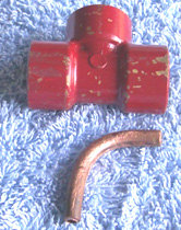 The copper pipe is then heated with a plumber’s gas torch and bent very slowly and carefully to the shape shown above. Some people find it helpful to insert a length of suitable flexible material into the pipe before starting the bending – something like the coiled steel spring material used to support net curtains – as that helps to keep the copper pipe from kinking when being bent. Next, the end of the copper pipe which will form the nozzle, is filled with silver solder and the end filed flat. Then, a small hole is drilled through that silver solder plug. The smallest possible drill bit should be used for this, although the hole may need to be drilled out to a slightly larger diameter, depending on what the engine requires (which is found by successive trials):  This Venturi tube is to be inserted into the last brass fitting before the engine, so a 1/4“ hole is drilled through the brass and then the drill is removed very slowly at a slight angle, the angle of drag being down the axis length of the brass fitting. The copper Venturi tube is then inserted through the hole and positioned so that the Venturi hole is aligned up exactly with the centreline of the brass fitting and positioned exactly in the middle of the cross-section of the brass fitting and then soldered in place: 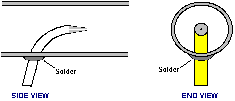 The method which Selwyn uses to block off the end of the copper tube with silver solder is to seal the far end of the tube with tape and fill the tube with fine-grained sand like this: 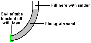 And then the tube is heated with the gas torch flame and the solder run into the top part of the tube. When the solder has cooled, the tape is removed and the sand removed by tapping the tube. When the hole has been drilled through the solder, air is blown through it to dislodge any remaining sand, and then water is forced through the hole. As the tube is short, any remaining sand can be removed with a pipe-cleaner or any similar slender cleaning device. The installed Venturi tube can be seen here: 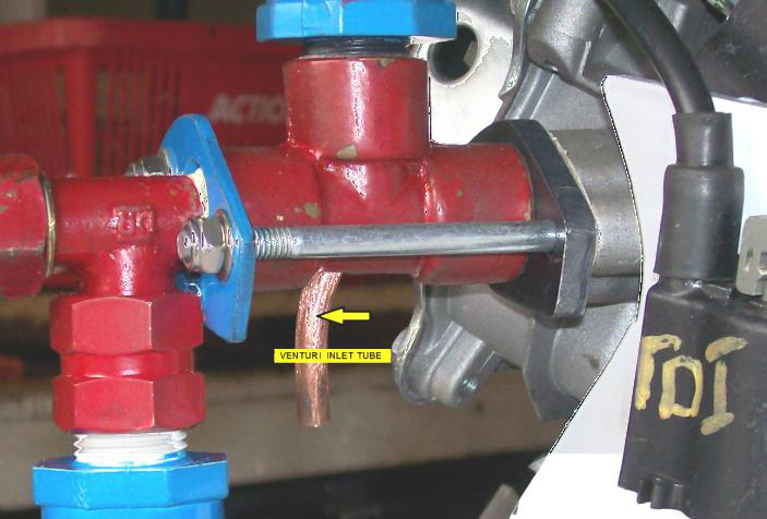 The second way to introduce cold water mist into the airstream entering the engine is to use a commercial “pond fogger” which can be bought at pet supplies outlets. These have to be powered electrically and housed in their own water container. Some of the more advanced versions float on the surface of the water so that the fog-generating section is always submerged to the ideal operational depth below the surface of the water. The generator should run well with 5 lpm of HHO gas plus cold water mist. Any design of electrolyser can be used. However, when used with rainwater, the Hogg electrolyser will draw about 1.4 amps per cell, giving a total input of about 115 watts when run on a 12-volt electrical supply. While rainwater is supposedly pure, the reality is that it seldom is and it’s ability to carry a current varies dramatically from place to place and even more widely from country to country. However, regarding the water, Selwyn says: The water I use is treated in a special way to make sure that the electrolyser runs at the lowest temperature and amperage possible. For this, using rain water is a must and the rain water coming off a steel roof is the best. The water is then treated by inserting a double coil of stainless steel wire into a volume of about 5 litres of water. A supply of 12-volts DC is applied to the coils, and the resulting current allowed to run through the coils for about 5 hours. This results in hot and very dirty water. The water is then filtered using a 0.5 micron filter making the water ready for use in the electrolyser. If more water is needed, say 30 litres, then leave the coils running for at least 24 hours. I use an old 35 litre beer keg and prepare 30 litres at a time. A major reason for doing this is to remove all the solids suspended in the water so that they will not clog up the stainless steel mesh inside the electrolyser. After the construction of the Hogg electrolyser is completed, then the stainless steel mesh electrodes need to be treated and cleaned. For this I use distilled water and fill the electrolyser enough to cover all the plates, and then add 1 packet of citric acid for each 3 litres of water used to fill the electrolyser. I got the citric acid from www.hho-research.com.au which is an Australia-only supplier and each packet has about 22 grams of citric acid in it:  The pumps are then run for about an hour after which the Hogg tubes are washed out completely with distilled water and then allowed to dry completely. This removes any residue from the stainless steel mesh electrodes, making the gas production rate much greater. I use an ordinary car battery to generate the HHO gas needed to start the generator running, after which, a standard battery charger powered by the generator output is used to keep the starting battery topped up. Please Note: This document has been prepared for information purposes only and must not be construed as an encouragement to build any new device nor to adapt any existing device. If you undertake any kind of construction work, then you do so entirely at your own risk. You, and only you, are responsible for your own actions. This document must not be seen as an endorsement of this kind of generator adaption nor as providing any kind of guarantee that an adaption of this kind would work for you personally. This document merely describes what has been achieved by other people and you must not consider it as being a foolproof blueprint for replication by anyone else. There are YouTube videos which show generators being operated on what appears to be just HHO gas alone and while the operation does not appear to be anywhere close to full power, the addition of cold water mist would probably make a major difference to the performance, but it does demonstrate that a generator can certainly be run without using any fossil fuel. The spark circuit in the first video appears to be powered by a small mains unit, but as the generator is lighting a powerful lamp, that electrical input could almost certainly be met by the output from the generator when it is running. The reason for the modification of standard generators as shown above is due to the fact that the HHO gas mix produced by an electrolyser, ignites about a thousand times faster than a hydrocarbon fuel, and because of that, the spark which ignites the fuel needs to be delayed. That mechanical adaption of the generator can be avoided if the HHO gas mix is modified so that it ignites more slowly. This can, and has been done. David Quirey of New Zealand has been operating an unmodified generator and a welding torch on the HHO output from his 6 lpm own-design of electrolyser, for many years now. Henry Paine’s US Letters Patent No. 308,276 dated 18th November 1884, states that HHO gas can be converted into a more convenient gas which is much easier to handle, by the simple process of bubbling it through a suitable liquid such as turpentine or linseed oil. Although unaware of Henry Paine's patent, David discovered the technique independently and he has extended the technology further so that the gas ignition speed can be set manually. One important point which David stresses is that it is essential that the HHO coming from the electrolyser is passed through an ordinary bubbler containing water, before it passes through the second bubbler containing the modifying liquid. David finds that the lighter liquid, acetone, works better than the liquids suggested by Henry Paine although white spirit, carbon tetrafluoride, aviation fuel, hexane or even petrol can be used and any of them will slow the flame speed right down to that of butane. If the flame is being used for a specialist task such as jewellery making or glass blowing, then there may be an advantage in using one particular modifying liquid. Please note that the bubbler holding the acetone needs to be made of stainless steel as acetone can dissolve some plastics. David has further modified the characteristics of the output gas by adding in a percentage of the unmodified HHO gas. Although it is actually, subtle and sophisticated, David’s overall system is easy to understand. The ratio of the two gasses is adjusted by the settings of the two control valves as shown here: 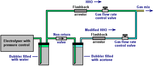 Adjusting the ratio of modified HHO to unmodified HHO allows a high degree of control over the characteristics of the resulting gas mix. Added to that, David has developed an electronic control system which oversees and manages the gas flow rate according to the user’s needs at any given moment. The result is a system which allows water and electricity to be the means of supplying a gas which can be used as a safe, general purpose fuel. If it is used to run a generator, then the system appears to become self-powered if part of the generator output is used to drive the electrolyser. It should be possible to substitute the modified gas mix for propane or butane and so operate a wide range of existing equipment for heating, cooking and/or lighting. David runs a 4 horsepower Honda generator using this system: 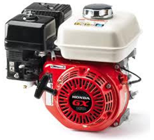 The generator runs very well for David, however, I suspect that if cold water mist were introduced into the incoming air, then the power output would be increased due to the mist turning into flash-steam and providing greater pressure on the piston during it’s power stroke. Alternatively, it might be possible to match the present performance with a lesser gas flow rate, possibly powering a much larger generator if that were a requirement. It needs to be understood that David uses electronics which manages and controls the gas flow volume, suiting it to whatever the needs are at any given moment. Consequently, it is probable that the six litres per minute which David’s electrolyser can produce, is not actually used for most of the time. David also does welding, brazing and cutting with the same modified electrolyser gas mix which can provide adjustable flame heat and a flame length of anything up to two feet in length: 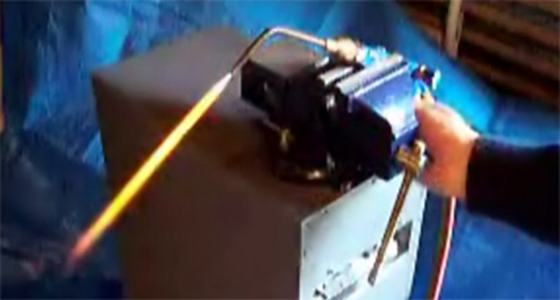 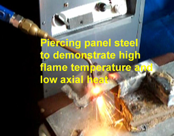 It is a good idea to use a proven design with full control electronics. David can help here with detailed step by step construction plans and instructional videos. 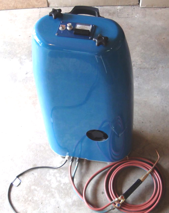 You can contact David at dahq@clear.net.nz for information on what is available to help you at the present time. When using the system for welding, David uses the mains to power the electrolyser, the arrangement being like this: 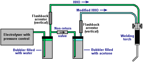 The flashback arrestors are a sand-filled design and so are mounted vertically. The gas production rate is knob controlled using this circuit: 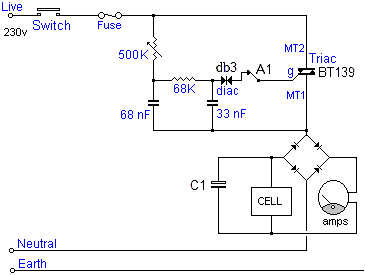 The first part of David Quirey’s circuit acts very much like a dimmer light switch. The 230-volt AC mains is fed through an On/Off switch and then an ordinary mains fuse. The current flow on through the circuit is blocked by the BT139 triac until it receives a pulse from the db3 diac (which is a component specifically designed to feed pulses to a triac). As the voltage builds up on the 68 nanofarad capacitor it eventually reaches the point at which it triggers the triac, which then switches on and remains on until the mains voltage drops down to zero again. The 500K variable resistor sets the rate at which the capacitor charges up, and so it controls the length of time that the triac is on in any given second (and so, the level of power fed onwards to the rest of the circuit). This happens on both the positive-going half of the AC waveform and the negative-going half of the mains sinewave voltage supply. Both the diac and the triac operate with AC and trigger either 100 or 120 times per second depending on the frequency at which the local mains runs. The current flow is then passed to a bridge rectifier in order to convert the AC into pulsing DC and the capacitor C1 which is 400-volt rated, smoothes the resulting DC. David’s cell has a large number of plates and so, operates off the 300 volts produced by this system. The ammeter between the diode bridge and the cell indicates the current flow and so, the amount of gas being produced at any given moment. The flashback arrestors are constructed as shown here: 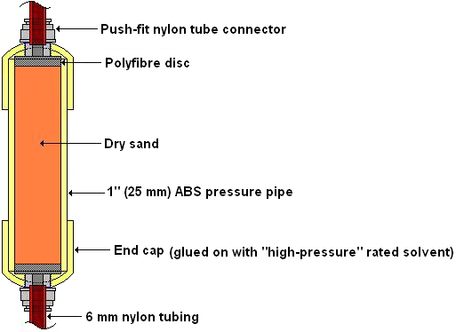 Sincere thanks are due to David Quirey for freely sharing his design and experiences. Patrick Kelly http://www.free-energy-info.com http://www.free-energy-info.tuks.nl |