|
Note: If you are not at all familiar with basic electronics, you might find it easier to understand this chapter if you read chapter 12 first.
There are two or three main objectives for people who create automotive devices – increasing the mpg performance and reducing the harmful emissions are the top two priorities, while running the vehicle on water alone is the aim of a few people. The first two objectives are readily achievable, but running a vehicle on water alone is not going to happen for almost everybody. This idea is peddled by con artists who sell worthless “plans”, claiming that these will run a vehicle on water for anybody who wants to construct these simple devices. This is just not true. You are welcome to download the "HydroStar" and "HydroGen" plans free from my web site: HydroStar and HydroGen. However, most experienced people looking at these plans are convinced that they could not possibly produce enough hydrogen/oxygen gas mix to run an engine. While I have never heard of anyone, anywhere, ever getting an engine to run on these plans, the present day science of water is so inadequate, that I am not in a position to be certain that they could not work, and so I am just highly doubtful about them being viable devices. Just before getting on to explain the construction details of practical systems, let me put the running of an engine on water alone in its proper context. The internal combustion engine which you own has an efficiency less than 50%. This means that at least half of the energy available from the fuel which you use is wasted and does not produce any useful mechanical output power. In many cases, that percentage can be as high as 90% inefficient, but let’s be generous and assume that your particular engine is especially good and manages 50% efficiency. The main way of running an engine with water as the only fuel, involves splitting water into hydrogen and oxygen and then burning those gases to power the engine. To be self-sustaining, the splitting of the water has to be done by the electrics of the vehicle and that means that the efficiency of the water splitting has to be more than 200% efficient. That just doesn’t happen with simple systems, so please forget the notion of building some device in your garage with a couple of hours work and waving goodbye to filling stations forever – it ain’t going to happen. Just to set the record straight, it is possible to run a vehicle without using fossil fuel, but the difficulty level of doing that is about the same as building a rocket capable of going into orbit, which is something well beyond the capabilities of most people, including me. This document does tell you how it can be done, but please understand that it calls for exceptional skills, very considerable expenditure and a great deal of patience, so for the time being, please forget about it. What can be done quite readily and at low cost, is to construct a device which will raise the efficiency of your engine. This is done by feeding a hydrogen/oxygen gas mix (called “hydroxy” gas) into your engine along with the air which is drawn in to make the engine run. A device of this type is called a “booster” as it boosts the fuel burn, extracting a greater percentage of the fuel’s available energy. An important side effect of this improvement in the burn quality of the fuel is the fact that unburnt fuel no longer gets pushed out of the exhaust as harmful emissions. Another effect is that the engine has greater pulling power and runs smoother. Inside your engine, carbon deposits will have built up from previous un-boosted running. These deposits get burnt away when you use a booster and that extends the engine life. Some people worry about the fact that burning hydroxy gas produces water and they imagine this water causing rusting inside the engine. What they don’t realise is that the ordinary fuel used in the engine is a “hydrocarbon” which is a compound of hydrogen and carbon and that fuel actually splits up to form hydrogen which the engine burns. It is the carbon part of the hydrocarbon fuel which is the problem, producing Carbon dioxide (greenhouse gas), Carbon monoxide, and physical carbon deposits inside the engine. A normal fuel burn produces water anyway, but you don’t get rusting inside the engine as the temperature there is so high that any water is in the form of steam or vapour which dry out completely when the engine is switched off. Adding a small amount of hydroxy gas has no adverse effects at all. This document describes different types of booster. Let me stress that each engine is different and it depends on how inefficient the engine is to begin with, what sort of mpg improvement is likely to be produced by a booster. Just to make sure that you understand what is involved, a booster is a simple container which holds a set of plates submerged in water which probably has an additive to make the water conduct electrical current better. A pipe from the top of the container feeds the gas into the air filter of the vehicle, via one or two simple safety devices. Adding this gas causes a major improvement in the quality of the fuel burn inside the engine and cuts harmful emission to near zero. As a consequence of this, it is possible to reduce the amount of fossil fuel being sent to the engine, which is not something which should be done if hydroxy gas is not being added, as the engine is liable to overheat and some valve damage could occur. It is a completely different matter if hydroxy gas is being added. However, all recent engine designs have an Electronic Control Unit (“ECU”) which controls the amount of fuel being sent to the engine. The ECU accepts input signals from an “oxygen sensor” placed in the exhaust stream, and often a second sensor after the catalytic converter to make sure that the catalytic converter has not failed. Unfortunately, the much improved exhaust caused by the better fuel burn caused by the hydroxy gas, causes the ECU to think that the engine fuel-air mix must be too low, and so it pumps in more fuel in an effort to compensate. Ideally, this can be dealt with by adding a circuit board which adjusts the signal coming from the oxygen sensor so that it is correct for the improved fuel burn. Details of how to do this are in a companion document. So, to recap, the only practical device which you can build yourself and use to improve automotive performance is a ‘booster’. Using a booster improves the efficiency of the fuel burn inside your engine and that results in more power, better torque, smoother running and vastly improved exhaust emissions. If the ECU is not adjusted or its input signal not controlled, the mpg figures may actually get slightly lower due to unwanted excess fuel being pumped into the engine. If a control circuit is used to correct this ECU error, then mpg gains will be produced. So, what mpg gains can be expected? The worst I have ever heard of was 8% which is very rare. The lowest likely gain is 20%. Typical gains are in the 25% to 35% bracket. Not particularly unusual is 35% to 60%, while gains up to 100% and over have been achieved but they are rare. A realistic expectation would be a 33% gain. This chapter is divided up into the following sections: 1. Simple DC boosters, using a 12-volt electrical input. 2. Advanced DC boosters using much higher DC voltages. 3. Water-splitters which use pulsed electrical signals to change water into "hydroxy" gas. 4. Running engines without fossil fuels. 5. Other useful devices. One thing which needs to be understood: Caution: A booster is not a toy. If you make and use one of these, you do so entirely at your own risk. Neither the designer of the booster, the author of this document or the provider of the internet display are in any way liable should you suffer any loss or damage through your own actions. While it is believed to be entirely safe to make and use a properly built booster, provided that the safety instructions shown in this document are followed, it is stressed that the responsibility for doing this is yours and yours alone. 1. Simple DC Boosters It is important that you understand the basic principles of electrolysis if you are to be successful in building and operating a booster, or alternatively, buying and operating a booster. A "DC booster" operates on "Direct Current" which is the sort of electrical power delivered by a car battery. The method is very simple in basic outline. Two metal plates are placed in water and an electric current is passed between the plates. This causes the water to break down into a mixture of hydrogen gas and oxygen gas (The two components used in the Space Shuttle). The greater the flow of current, the larger the volume of gas which will be produced. The arrangement is like this:  Remembering that the result of doing this is to produce fuel for the Space Shuttle, you should avoid doing this indoors and letting the gas produced by the process collect on the ceiling. There are many videos on the web where people act in a dangerous manner and perform electrolysis indoors using a container which is open at the top as shown above. Please, please don't do that as it is highly dangerous - it is not a party popper which pushes the Space Shuttle into space! If you were to collect a cupful of hydroxy gas and light it, the resulting explosion would probably damage your hearing permanently, so don't do it under any circumstances. Just like the fact that a very useful chain saw is a dangerous device which needs to be treated with respect, so too, please understand that the very useful hydroxy gas mix contains a lot of energy and so needs to be treated with respect. This style of electrolysis of water was investigated by the very talented and meticulous experimenter Michael Faraday. He presented his results in a very technical and scientific format which are not understood by most ordinary people. But in simple terms, he tells us that the amount of hydroxy gas produced is proportional to the current flowing through the water, so to increase the rate of gas production, you need to increase the current flow. Also, he found that the optimum voltage between the two "electrode" plates is 1.24 volts. This sounds a bit technical, but it is a highly useful piece of information. In the arrangement shown above, twelve volts is being connected across two plates in water. Faraday tells us that only 1.24 volts of that twelve volts will go to make hydroxy gas and the remaining 10.76 volts will act as an electric kettle and just heat the water, eventually producing steam. As we want to make hydroxy gas and not steam, this is bad news for us. What it does tell us is that if you choose to do it that way, then only 10% of the power taken by the booster actually makes hydroxy gas and a massive 90% is wasted as heat. We really don't want a low electrical efficiency like that. One way around the problem is to use two cells like this:  This arrangement uses our 1.24 volts twice while the twelve volts stays unchanged and so the electrical efficiency goes up to 20% and the heat loss drops to 80%. That is quite an improvement but even more important is the fact that twice as much hydroxy gas is now produced, so we have doubled the electrical efficiency and doubled the gas output, giving a result which is four times better than before. We could go one step further and use three cells like this:  This time we are using three of our 1.24 volt sections and this gives us an electrical efficiency of 30% and three times the amount of gas, making the system nine times more effective. This is definitely going in the right direction, so how far can we take it when using a twelve volt battery? When we use the construction materials which years of testing has shown to be particularly effective, there is a small voltage drop across the metal plates, which means that the very best voltage for each cell is about 2 volts and so with a twelve volt battery, six cells is about the best combination, and that gives us an electrical efficiency of 62% and six times as much gas, which is 37 times better than using a single cell, and the wasted electrical power drops down from 90% to 38%, which is about as good as we can get. Of course, it would not be practical to have six boxes each as large as a car battery as we would never manage to fit them into most vehicles. Perhaps we could just put all the plates inside a single box. Unfortunately, if we do that, a good deal of the electric current would flow around the plates and not make much gas at all. A top view of this arrangement is shown here:  This is a disaster for us as now we will not get your six times the gas production or our massively reduced heating. Thankfully, there is a very simple fix for this problem, and that is to divide the box up into six watertight compartments using thin partitions like this:  This gives us back our high efficiency by blocking the current flow past the plates and forcing the current to flow through the plates, producing gas between every pair of plates. In passing, if this booster were to be powered by the electrics of a vehicle, then the voltage although called "twelve volts" will actually be almost fourteen volts when the engine is running so that the "twelve volt" battery will get charged. This would allow us to use seven cells inside our electrolyser, rather than the six cells shown above and that would give us seven times the gas volume that a single pair of plates would give. Some people prefer six cells, and others, seven cells - the choice is up to the person constructing the unit. We have been discussing the methods of increasing the gas production and reducing the wasted energy, but please don't assume that the objective is to make large volumes of hydroxy gas. It has been found that with many vehicle engines, very good performance gains can be had with a hydroxy gas production rate of less than 1 litre per minute ("lpm"). Flow rates of as little as 0.5 to 0.7 lpm are frequently very effective. Remember, the hydroxy gas from a booster is being used as an igniter for the regular fuel used by the engine and not as an additional fuel. The big advantage of an efficient booster design is that you can produce the wanted volume of gas using a much lower current, and so, a lesser extra load on the engine. Admittedly, there is not much additional engine load needed by a booster, but we should reduce the extra amount by intelligent design. In the discussion above, the battery has been shown connected directly across the booster or "electrolyser". This should never be done as there is no protection against a short-circuit caused by a loose wire or whatever. There should be a fuse or a circuit-breaker as the first thing connected to the battery. Circuit breakers are available from any electrician's supply outlet as they are used in the "fuse box" in homes, to provide protection for each lighting circuit and each power socket circuit. They are not expensive as they are manufactured in very large volumes. They are also available on eBay. The circuit breaker is wired like this:  a common design (rated at 32 amps) looks like this:  Some would-be constructors feel that some aspects of the construction are too difficult for them. Here are some suggestions which might make construction more straightforward. Constructing a seven-cell housing is not difficult. Pieces are cut out for two sides, one base, one lid and six absolutely identical partitions. These partitions must be exactly the same so that there is no tendency for leaks to develop. If you decide to use the bent-plate system of electrodes shown on the next few pages, then drill the bolt holes in the partitions before assembling them:  The bottom piece is the same length as the sides, and it is the width of the partitions plus twice the thickness of the material being used to build the housing. If acrylic plastic is being used for the construction, then the supplier can also provide an “adhesive” which effectively “welds” the pieces together making the different pieces appear to have been made from a single piece. The case would be assembled like this:  Here, the partitions are fixed in place one at a time, and finally, the second side is attached and will mate exactly as the partitions and ends are all exactly the same width. A simple construction for the lid is to glue and screw a strip all the way around the top of the unit and have the lid overlap the sides as shown here:  A gasket, perhaps of flexible PVC, placed between the sides and the lid would assist in making a good seal when the lid is bolted down. The gas outlet pipe is located in the centre of the lid which is a position which is not affected if the unit is tilted when the vehicle is on a steep hill. Years of testing have shown that a really good choice of material for the electrode plates is 316-L grade stainless steel. However, it is very difficult to connect those plates electrically inside the cells as you need to use stainless steel wire to make the connections and bolted connections are really not suitable. That leaves welding the wires to the plates and welding stainless steel is not something which a beginner can do properly as it is much more difficult than welding mild steel. There is a good alternative, and that is to arrange the plate material so that no wire connections are needed:  While this six-cell design may look a little complicated to a quick glance, it is really a very simple construction. Each of the plates used in the central cells is just this shape:  The plate shapes shown above are arranged so that there is access to the bolts from above and they can be reached by a spanner and held steady while the other nut is being tightened. Unless you are skilled in bending plates, I suggest that you use stainless steel mesh for the plates. It works very well, can be readily cut using tin snips or any similar tool and it can be bent into shape by the home constructor using simple tools - a vice, a piece of angle iron, a small piece of mild steel sheet, a hammer, etc. You will find a skip outside any metal fabrication shop where scrap pieces are tossed for recycling. There will be off-cuts of various sizes of angle iron and all sorts of other small sections of sheet and strip. They are in the skip mainly to get rid of them as the fabrication business gets paid almost nothing for them. You can use some of these pieces to shape your booster plates, and if you feel bad about costing the business about a penny, then by all means put them back in the skip afterwards. If you clamp your plate between two angle irons in a vice, then careful, repeated gently tapping with a hammer close to the bend location, will produce a very clean and neat bend in the plate:  The bent sheet can then be clamped between two steel strips and a sharp U-shaped bend produced by tapping with a hammer, again, along the line of the required bend:  The thickness of the steel bar on the inside of the bend has to be the exact width of the required gap between the finished plate faces. This is not particularly difficult to arrange as 3 mm, 3.5 mm, 4 mm, 5 mm and 6 mm are common thicknesses used in steel fabrication, and they can be combined to give almost any required gap. There are many varieties of stainless steel mesh. The style and thickness are not at all critical but you need to choose a type which is reasonably stiff and which will hold its shape well after it is bent. This style might be a good choice:  Your local steel supplier probably has some types on hand and can let you see how flexible a particular variety is. The shape shown above is for a "three plate per cell" design where there are two active plate faces. Ideally, you want two to four square inches of plate area per amp of current flowing through the cell, because that gives very long electrode life and minimum heating due to the plates. This style of construction is reasonably easy to assemble as the two bolts which pass through the partitions and which hold the plates rigidly in place, can be accessed from above, two spanners being used to lock them tight. Lock nuts are optional. If you feel that your particular mesh might be a little too flexible or if you think that the bolts might eventually loosen, then you can attach two, or more, separator insulating pieces - plastic washers, plastic bolts, cable ties or whatever to one of the plate faces. These will hold the plates apart even if they were to become loose. They also help to maintain the gap between the plates. This gap has to be a compromise because the closer the plates are together, the better the gas production but the more difficult it is for the bubbles to break away from the plates and float to the surface and if they don't do that, then they block off some of the plate area and prevent further gas production from that part of the plate as the electrolyte no longer touches the plate there. A popular choice of gap is 1/8 inch which is 3 mm as that is a good compromise spacing. Circular spacers would look like this:  If the current is low enough, an even more simple shape which has just a single pair of active plate surfaces per cell, can be used as shown here:  Any of these designs can be 6-cell or 7-cell and the plates can be constructed without outside help. You will notice that the electrical connections at each end of the booster are submerged to make sure that a loose connection can't cause a spark and ignite the hydroxy gas in the top of the housing. There should be a gasket washer on the inside to prevent any leakage of the electrolyte past the clamping bolt. If you want to use three active plate pairs in each cell, then the plate shape could be like this:  The electrolyte is a mix of water and an additive to allows more current to flow through the liquid. Most of the substances which people think of to use to make an electrolyte are most unsuitable, producing dangerous gasses, damaging the surfaces of the plates and giving uneven electrolysis and currents which are difficult to control. These include salt, battery acid and baking soda and I strongly recommend that you do not use any of these. What is needed is a substance which does not get used up during electrolysis and which does not damage the plates even after years of use. There are two very suitable substances for this: sodium hydroxide, also called "lye" or "caustic soda". In the USA, this is available in Lowes stores, being sold as "Roebic ‘Heavy Duty’ Crystal Drain Opener". The chemical formula for it is NaOH. One other substance which is even better is potassium hydroxide or "caustic potash" (chemical formula KOH) which can be got from soap-making supply shops found on the web. Both NaOH and KOH are very caustic materials and they need to be handled with considerable care.  Bob Boyce of the USA is one of the most experienced people in the construction and use of boosters of different designs. He has kindly shared the following information on how to stay safe when mixing and using these chemicals. He says: These materials are highly caustic and so they need to be handled carefully and kept away from contact with skin, and even more importantly, eyes. If any splashes come in contact with you, it is very important indeed that the affected area be rinsed off immediately with large amounts of running water and if necessary, the use of vinegar which is acidic and so will neutralise the caustic liquid. When making up a solution, you add small amounts of the hydroxide to distilled water held in a container. The container must not be glass as most glass is not high enough quality to be a suitable material in which to mix the electrolyte. The hydroxide itself should always be stored in a sturdy, air-tight container which is clearly labelled "DANGER! - Potassium (or Sodium) Hydroxide". Keep the container in a safe place, where it can’t be reached by children, pets or people who won't take any notice of the label. If your supply of hydroxide is delivered in a strong plastic bag, then once you open the bag, you should transfer all of its contents to sturdy, air-tight, plastic storage containers, which you can open and close without any risk of spilling the contents. Hardware stores sell large plastic buckets with air tight lids that can be used for this purpose. When working with dry hydroxide flakes or granules, wear safety goggles, rubber gloves, a long sleeved shirt, socks and long trousers. Also, don’t wear your favourite clothes when handling hydroxide solution as it is not the best thing to get on clothes. It is also no harm to wear a face mask which covers your mouth and nose. If you are mixing solid hydroxide with water, always add the hydroxide to the water, and not the other way round, and use a plastic container for the mixing, preferably one which has twice the capacity of the finished mixture. The mixing should be done in a well-ventilated area which is not draughty as air currents can blow the dry hydroxide around. When mixing the electrolyte, never use warm water. The water should be cool because the chemical reaction between the water and the hydroxide generates a good deal of heat. If possible, place the mixing container in a larger container filled with cold water, as that will help to keep the temperature down, and if your mixture should “boil over” it will contain the spillage. Add only a small amount of hydroxide at a time, stirring continuously, and if you stop stirring for any reason, put the lids back on all containers. If, in spite of all precautions, you get some hydroxide solution on your skin, wash it off with plenty of cold running water and apply some vinegar to the skin. Vinegar is acidic, and will help balance out the alkalinity of the hydroxide. You can use lemon juice if you don't have vinegar to hand - but it is always a good idea to have a bottle of vinegar handy. The concentration of the electrolyte is a very important factor. Generally speaking, the more concentrated the electrolyte, the greater the current and the larger the volume of hydroxy gas produced. However, there are three major factors to consider: 1. The resistance to current flow through the metal electrode plates. 2. The resistance to current flow between the metal plates and the electrolyte. 3. The resistance to current flow through the electrolyte itself. 1. In a good electrolyser design like those shown above, the design itself is about as good as a DC booster can get, but understanding each of these areas of power loss is important for the best possible performance. We were taught in school that metals conduct electricity, but what was probably not mentioned was the fact that some metals such as stainless steel are quite poor conductors of electricity and that is why electrical cables are made with copper wires and not steel wires. This is how the current flow occurs with our electrolyser plates:  The fact that we have folds and bends in our plates has no significant effect on the current flow. Resistance to current flow through the metal electrode plates is something which can’t be overcome easily and economically, and so has to be accepted as an overhead. Generally speaking, the heating from this source is low and not a matter of major concern, but we provide a large amount of plate area to reduce this component of power loss as much as is practical. 2. Resistance to flow between the electrode and the electrolyte is an entirely different matter, and major improvements can be made in this area. After extensive testing, Bob Boyce discovered that a very considerable improvement can be made if a catalytic layer is developed on the active plate surface. Details of how this can be done are given later in the companion document "D9.pdf" as part of the description of Bob’s electrolyser.  3. Resistance to flow through the electrolyte itself can be minimised by using the best catalyst at its optimum concentration. When using sodium hydroxide, the optimum concentration is 20% by weight. As 1 cc of water weighs one gram, one litre of water weighs one kilogram. But, if 20% (200 grams) of this kilogram is to be made up of sodium hydroxide, then the remaining water can only weigh 800 grams and so will be only 800 cc in volume. So, to make up a 20% "by weight" mix of sodium hydroxide and distilled water, the 200 grams of sodium hydroxide are added (very slowly and carefully, as explained above by Bob) to just 800 cc of cool distilled water and the volume of electrolyte produced will be about 800 cc. When potassium hydroxide is being used, the optimum concentration is 28% by weight and so, 280 grams of potassium hydroxide are added (very slowly and carefully, as explained above by Bob) to just 720 cc of cold distilled water. Both of these electrolytes have a freezing point well below that of water and this can be a very useful feature for people who live in places which have very cold winters. Another factor which affects current flow through the electrolyte is the distance which the current has to flow through the electrolyte - the greater the distance, the greater the resistance. Reducing the gap between the plates to a minimum improves the efficiency. However, practical factors come into play here as bubbles need sufficient space to escape between the plates, and a good working compromise is a spacing of 3 mm. which is one eighth of an inch.  However, there is a problem with using the optimum concentration of electrolyte and that is the current flow caused by the greatly improved electrolyte is likely to be far more than we want. To deal with this we can use an electronic circuit called a "Pulse-Width Modulator" (or “PWM”) circuit. These are often sold as "DC Motor Speed Controllers" and if you buy one, then pick one which can handle 30 amps of current. A PWM circuit operates in a very simple way. It switches the current to the electrolyser On and Off many times every second. The current is controlled by how long (in any one second) the current is On, compared to how long it is Off. For example, if the On time is twice as long as the Off time (66%), then the average current flow will be much greater than if the On time were only half as long as the Off time(33%). When using a PWM controller, it is normal to place its control knob on or near the dashboard and to mount a simple low-cost ammeter beside it so that the driver can raise or lower the current flow as is considered necessary. The arrangement is like this:  There is a more sophisticated circuit controller called a "Constant-current Circuit" and that allows you to select the current you want and the circuit then holds the current at your set value at all times. However, this type of circuit is not readily available for sale although some outlets are preparing to offer them. Some of the most simple boosters don't use a PWM circuit because they control the current flow through the booster by making the concentration of the electrolyte very low so that the resistance to current flow through the electrolyte chokes off the current and holds it down to the desired level. This, of course, is far less efficient and the resistance in the electrolyte causes heating, which in turn, is an operational problem which needs careful handling by the user. The advantage is that the system appears to be more simple. Feeding the hydroxy gas to the engine. When using a booster of any design you need to realise that hydroxy gas is highly explosive. If it wasn’t, it would not be able to do it’s job of improving the explosions inside your engine. Hydroxy gas needs to be treated with respect and caution. It is important to make sure that it goes into the engine and nowhere else. It is also important that it gets ignited inside the engine and nowhere else. To make these things happen, a number of common-sense steps need to be taken. Firstly, the booster must not make hydroxy gas when the engine is not running. The best way to arrange this is to switch off the current going to the booster when the engine is not running. It is not sufficient to just have a manually-operated On/Off switch as it is almost certain that switching off will be forgotten one day. Instead, the electrical supply to the booster is routed through the ignition switch of the vehicle. That way, when the engine is turned off and the ignition key removed, it is certain that the booster is turned off as well. So as not to put too much current load on the ignition switch, and to allow for the possibility of the ignition switch being on when the engine is not running, instead of wiring the booster directly to the switch, it is better to wire a standard automotive relay across the oil pressure unit and let the relay carry the booster current. The oil pressure drops when the engine stops running, and so this will also power down the booster. An extra safety feature is to allow for the (very unlikely) possibility of an electrical short-circuit occurring in the booster or its wiring. This is done by putting a fuse or contact-breaker between the battery and the new circuitry as shown in this diagram:  If you choose to use a contact-breaker, then a light-emitting diode (“LED”) with a current limiting resistor of say, 680 ohms in series with it, can be wired directly across the contacts of the circuit breaker. The LED can be mounted on the dashboard. As the contacts are normally closed, they short-circuit the LED and so no light shows. If the circuit-breaker is tripped, then the LED will light up to show that the circuit-breaker has operated. The current through the LED is so low that the electrolyser is effectively switched off when the contact breaker opens. This is not a necessary feature, merely an optional extra:  A good source for general components needed in building boosters is The Hydrogen Garage in the USA, website. A very important safety item for any booster is the “bubbler” which is just a simple container with some water in it. The bubbler has the gas coming in at the bottom and bubbling up through the water. The gas collects above the water surface and is then drawn into the engine through an outlet pipe above the water surface. To prevent water being drawn into the booster when the booster is off for any length of time and the pressure inside it reduces, a one-way valve is placed in the pipe between the booster and the bubbler. If the engine happens to backfire, then the bubbler blocks the flame from passing back through the pipe and igniting the gas being produced in the booster. A bubbler is a very simple, very cheap and very sensible thing to install. It also removes any traces of electrolyte fumes from the gas before it is drawn into the engine. In practice, it is a very good idea to have two bubblers, one close to the booster and one close to the engine. The second bubbler makes sure that every last trace of electrolyte fumes are washed out of the hydroxy gas before it enters the engine. There are various ways to make a good bubbler. In general, you are aimed at having a five-inch (125 mm) depth of water through which the hydroxy gas must pass before it leaves the bubbler. It is recommended that a bubbler is built inside a strong container such as this one:  These strong containers are generally sold as water filters. They can be adapted to become bubblers without any major work being done on them. At this point, we need to consider the mechanism for moving the hydroxy gas out of the booster and into the engine. It is generally a good idea to position the gas take-off pipe in the centre of the lid so that if the booster gets tilted due to the vehicle operating on a sloped surface, then the surface level of the liquid remains unchanged underneath the gas pipe. A common mistake is to use a gas pipe which has a small diameter. If you take a length of plastic pipe of a quarter inch diameter (6 mm) and try blowing through it, you will be surprised at how difficult it is to blow through. There is no need to give your booster that problem, so I suggest that you select a gas pipe of half an inch (12 mm) or so. If in doubt as to how suitable a pipe is, then try blowing through a sample length of it. If you can blow through it without the slightest difficulty, then it is good enough for your booster. One other thing is how to deal with splashes and the spray from bubbles bursting at the surface of the electrolyte. You want some device which will prevent any spray or splashes caused by the vehicle going over a very rough road, from entering the gas pipe and being drawn out of the booster along with the hydroxy gas. Various methods have been used and it is very much a matter of personal choice as to how you decide to deal with the issue. One method is to use a piece of suitable material across the end of the pipe. This is generally called anti-slosh material because of the job which it does. The material needs to let the gas pass freely through it but prevent any liquid getting through it. Plastic pot-scrubbers as a possible material as they have an interlocking mesh of small flat strands. The gas can flow around and through the many strands, but splashes which go in a straight line will hit the strands and drip back into the booster again. Another possible device is one or more baffles which will catch the liquid but let the gas pass freely by: 
OR 
OR  The hydroxy gas produced by a DC booster of this type contains about 30% monatomic hydrogen, which means that 30% of the hydrogen is in the form of single atoms of hydrogen and not combined hydrogen pairs of atoms. The monatomic form is about four times more energetic than the combined form and so it takes up a greater volume inside the booster housing. If the booster is left turned off for a long period of time, then these single hydrogen atoms will eventually bump into each other and combine to form the less energetic diatomic form of the gas. As this takes up less space inside the booster, the pressure inside the booster drops and this has been known to suck water out of the bubbler back into the booster. We don't want this to happen as it dilutes our carefully measured electrolyte concentration and it can make the bubbler ineffective due to lack of water. To deal with this, a one-way valve is put between the booster and the bubbler, positioned so that it does not allow flow back into the booster. In very cold climates, a 28% by weight potassium hydroxide electrolyte will not freeze until -40o C, it is more difficult to stop the bubblers freezing. While it is possible to have equipment which unplugs and can be taken indoors overnight, an alternative is to use alcohol or paraffin (kerosene) instead of water and they generally do not freeze and their fumes are not harmful to an engine.  The bubbler design is not difficult. Ideally, you want a very large number of small bubbles to be formed and float upwards through the water. This is because it gives the best connection between the gas and the water and so can do a really good job of washing any traces of hydroxide vapour out of the hydroxy gas before it gets fed to the engine. Small bubbles are also better separated from each other and so there is no real chance of a flame passing through the water where large bubbles might merge together and form a column of gas as they rise to the surface.  In this good bubbler design, the pipe which feeds the hydroxy gas into the bubbler is bent into an L-shape. The end of the pipe is blocked off, and many small holes are drilled in the horizontal section of the pipe. Only a few holes are seen in this diagram, but there will be a large number in the actual construction. Like the booster itself, the gas outlet pipe needs to be protected from splashes of water caused by the vehicle going over a bump. It is very important to make sure that water is not drawn into the engine along with the gas, so anti-slosh material or one or more baffles are used to prevent this happening. So the overall protection for the gas flow is:  Where the first bubbler is close to the booster and the second one is placed close to the engine. Once in a while, the water from the first bubbler can be used to top up the water inside the booster so that any traces of hydroxide which may have reached the bubbler are returned to the booster, keeping its electrolyte concentration exactly right and making sure that the water in the bubbler is always fresh. There is one final item which is an optional extra. Some people like to add a gas-pressure switch. If, for any reason, the pressure starts to rise - say that the outlet pipe became blocked - then the pressure switch would disconnect the electrical supply and stop the pressure rising any further: 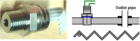 One decision which has to be made is the rate of hydroxy gas production which is the best for you. Most people seem to think that the larger the volume of hydroxy gas the better. That is not necessarily true because a very effective use of the gas is to make it act as an igniter for the engine's normal fuel and very satisfactory results have been achieved with hydroxy gas flow rates in the range of 0.4 to 0.7 litres per minute. You control the rate of gas production by controlling the current, either by the concentration of the electrolyte or by adjusting the current flow using an electronic circuit. Each litre of water produces about 1,750 litres of hydroxy gas, so you can estimate the length of time the booster can operate on one litre of water. If, for example, your booster is producing 0.7 litres of gas per minute. Then, it will produce 1,750 litres in 1,750 / 0.7 minutes and that is 2,500 minutes or 41 hours 40 minutes. As the booster only operates when you are driving, you are looking at 41 hours of driving time and if you drive about two hours per day, it would take three weeks to use one litre of water. The internal dimensions of your booster allow you to calculate how far the electrolyte level will drop if one litre of water is taken out of it. Generally speaking, it is normally considered that topping up the booster with water by hand every so often, is a perfectly good method of operation. The booster design described above has a good electrolyte capacity in each cell and so topping up with water should not be a major task. As tap water and well water have a good deal of dissolved solids in them, when the water is taken away by electrolysis, these solids drop out of solution and fall to the bottom of the housing, and/or coat the plates with an layer of unwanted material. For this reason, life is so much easier if distilled water is used for making electrolyte and for topping up the booster after use. It is possible to have an automatic water supply for your booster even though that is probably over-kill for such a simple device. If you decide to do that, then you need a water supply nozzle for each of your six or seven cells. It is not necessary for the electrolyte level to be exactly the same in each cell, but you would normally have them at roughly the same height. Your automated water supply could be like this:    A point which might not be immediately obvious is that because the gas pressure inside the booster is probably about 5 pounds per square inch ("psi"), once the water pump stops pumping, it is possible for the gas pressure to push out the remaining water in the inlet pipes and escape through the body of the pump. To prevent this, an ordinary one-way valve is put in the water supply pipe to prevent flow back towards the pump. Up to now, the hydroxy gas feed to the engine has just been indicated in a vague way in spite of the connection point being important. With most engines, the hydroxy gas should be fed into the air filter where it mixes well and is fully dispersed inside the air being drawn into the engine. You sometimes see diagrams which show the connection point being close to the engine intake manifold. This is not a good idea because the lowered pressure there causes reduced pressure inside the booster which in turn produces more unwanted hot water vapour, so stick with feeding the gas into the air filter. If there is a supercharger on the engine, then feed the hydroxy gas into the low-pressure side of the supercharger. The style of booster described above has the advantages of high electrical efficiency, easy construction, very few specialist parts and a large electrolyte volume per cell. There are many other very successful booster designs which have very different forms of construction. One of these is the "Smack's Booster" where electrical cover plates are clamped together and placed inside a length of plastic pipe:  The advantages of this design are the very simple construction, compact size, reasonable performance and the fact that you can buy one ready-made if you want to. You can download a copy of the construction details free from here The electrical efficiency of this design is lowered a bit because only a single body of electrolyte is used and so current can bypass the plates. The overall performance is a respectable 1.3 lpm for 20 amps, though you may wish to lower the current and settle for about half that rate of hydroxy gas production. Another design which is very easy to build is the "HotSabi" booster, which is a single threaded rod inside a length of plastic pipe with a stainless steel inner lining. It has the lowest possible electrical efficiency, being just a single cell with the full vehicle voltage connected directly across it, but in spite of that, it's performance in actual on the road use has been remarkable, with a reported 50% improvement on a 5 litre capacity engine. This excellent performance is probably due to the design having a steam trap which removes the hot water vapour produced by the excessive heating caused by having only a single cell with so much voltage across it (remember, 90% of the power supplied to this booster design goes in heating the electrolyte). 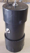  As the designer of this booster has freely shared his design, the free construction plans can be downloaded from here The construction of a 5 lpm version is here. Zach West's Electrolyser Zach West of the USA has produced a motorcycle electrolyser. Zach’s 250 cc motorcycle can run on the output of his electrolyser and Zach estimates the output as being 17 litres per minute of HHO gas, which seems to me to be far too high for the current flow. This is not a COP>1 system as the output from the electrical system of the motorcycle is very limited, and so the battery will slowly run down as time goes by. However, Zach’s design of electrolyser is interesting, both for it’s simplicity and it’s high rate of gas output. The increased gas volume which would be produced if this design were adapted for, and driven by, a 12-volt input could be very useful, especially if combined with David Quirey’s system which allows the resulting modified gas to operate in unmodified engines, as shown later on in this chapter. The method which Zach uses is somewhat unusual as he manages to bleed off and discard most of the oxygen produced. This means that the remaining gas is mainly hydrogen which is far less explosive than HHO which is already in the perfect proportions for combination back into water and so is highly reactive. Instead, the resulting gas can be compressed reasonably well, and Zach compresses it to 30 psi (pounds per square inch) in a storage container. This helps with acceleration from stationary at traffic lights. Zach uses a simple, modular style of construction where a series of coiled electrode pairs are each placed inside an individual length of plastic pipe. This is a design which is neither difficult nor particularly expensive to build. In overall broad outline, Zach’s electrolyser is fed water from a water tank to keep it topped up. The electrolyser box contains several pairs of electrodes which split the water into hydrogen and oxygen when fed with pulsed electrical current generated by the electronics, which is powered by the electrical system of the motorcycle. The gas produced by the electrolyser is fed to a dual-purpose bubbler, which prevents any accidental igniting of the gases from travelling back to the electrolyser and in addition, removes most of the oxygen from the gas by acting as a gas “separator”. The arrangement is like this:  The hydrogen gas output from the electrolyser is not fed directly to the engine but instead it goes to a pressure tank which is allowed to build up to thirty pounds per square inch before the engine is started. The majority of the oxygen produced by the electrolysis is vented away through a 30 psi one-way valve which is included to keep the pressure inside the bubbler (and the electrolyser) at the 30 psi level. That pressure is excessive for a high-performance electrolyser which produces HHO which is highly charged electrically and so will explode spontaneously when compressed, due to it’s own electrical charge. In this simple DC electrolyser, the HHO gas is mixed with quite an amount of water vapour which dilutes it and allows some compression. The water supply system operates by having an air-tight supply tank positioned at a higher level than the electrolyser. A small diameter (1/4” or 6 mm) plastic tube coming from the supply tank feeds through the top of the electrolyser and straight down, terminating at exactly the electrolyte surface level wanted in each of the electrolyser tubes. When the electrolysis lowers the electrolyte level below the bottom of the pipe, bubbles of gas pass up the tube allowing some water to flow from the tank to raise the electrolyte surface level back to it’s design position. This is a very neat passive system needing no moving parts, electrical supply or electronics but yet one which accurately controls the electrolyte level. One essential point to understand is that the water tank needs to be rigid so that it will not flex and the filler cap needs to be air-tight to prevent the entire water supply discharging into the electrolyser. Another point to remember when topping up the water tank is that the tank contains a mix of air and HHO gas above the water surface and not just plain air, and that gas mix is at 30 psi pressure. Now, to cover the design in more detail. This 6-volt electrolyser contains eight pairs of electrodes. These electrode pairs are coiled around in “Swiss-roll” style and inserted into a length of 2 inch (50 mm) diameter plastic pipe, ten inches (250 mm) tall. The electrodes are each made from a 10 inch (250 mm) by 5 inch (125 mm) of 316L-grade stainless steel shimstock which is easy to cut and work. Shimstock is available from a local steel supplier or metal fabrication company and is just a sheet of very thin metal. Each electrode is cleaned carefully, and wearing rubber gloves, cross-scored using coarse sandpaper in order to produce a very large number of microscopic mountain peaks on the surface of the metal. This increases the surface area and provides a surface which makes it easier for gas bubbles to break away and rise to the surface. The electrodes are rinsed off with clean water and then coiled round, using spacers to maintain the necessary inter-plate gap, to form the required shape which is then inserted into a length of plastic pipe as shown here:  As the springy metal pushes outwards in an attempt to straighten up again, spacers are used to keep the electrodes evenly separated along their whole length by inserting 1/8” thick vertical spacer strips. The connections to the plates are made by drilling a hole in the corner of the plate and inserting the wire several times through the hole, twisting it back around itself and making a wire-to-wire solder joint on both sides of the steel. The joint is then insulated with silicone or any other suitable material. It is, of course, essential that the joint does not short-circuit to the other electrode even though that electrode is very close by.  It is always difficult to make a good electrical connection to stainless steel plates if space is restricted as it is here. In this instance, the electrical wire is wrapped tightly through a drilled hole and then soldered and insulated. The soldering is only on the wire as solder will not attach to stainless steel. An unusual feature of this design is that each of the electrode pairs is effectively a separate electrolyser in its own right as it is capped top and bottom, and effectively physically isolated from the other electrodes. The water feed comes through the top cap which has a hole drilled in it to allow the gas to escape. The electrical wires (#12 AWG or swg 14) are fed through the base and sealed against leakage of electrolyte. Each of these units has some electrolyte stored above it, so there is no chance of any part of the electrode surface not being able to generate gas. There is also a large amount of freeboard to contain splashes and sloshing without any being able to escape from the container. The end caps are standard PVC caps available from the supplier of the PVC piping, as is the PVC glue used to seal them to the pipe. Eight of these electrodes are placed in a simple electrolyser case and connected together in pairs as shown here:  Pairs of pipe-enclosed electrode spirals are then connected in a chain inside the electrolyser as shown here:  Many years of experimentation and testing have shown that 316L-grade stainless steel is the most suitable material for electrodes, but surprisingly, stainless steel is not highly electrically conductive as you would expect. Each electrode causes a voltage drop of nearly half a volt, and so careful surface preparation, cleansing and conditioning are needed to get top performance from the electrodes. This process is described in detail by the very experienced Bob Boyce who says: The preparation of the plates is one of the most important steps in producing an electrolyser which works well. This is a long task, but it is vital that it is not skimped or hurried in any way. Surprisingly, brand new shiny stainless steel is not particularly suitable for use in an electrolyser and it needs to receive careful treatment and preparation before it will produce the expected level of gas output. The first step is to treat both surfaces of every plate to encourage gas bubbles to break away from the surface of the plate. This could be done by grit blasting, but if that method is chosen, great care must be taken that the grit used does not contaminate the plates. Stainless steel is not cheap and if you get grit blasting wrong, then the plates will be useless as far as electrolysis is concerned. A safe method is to score the plate surface with coarse sandpaper. This is done in two different directions to produce a cross-hatch pattern. This produces microscopic sharp peaks and valleys on the surface of the plate and those sharp points and ridges are ideal for helping bubbles to form and break free of the plate.  When doing hand sanding the sandpaper is drawn across the plates in one direction only and not backwards and forwards, as the backwards stroke always destroys the perfectly good ridges created on the forward stroke. Also, you only need two strokes in one direction before turning the plate through ninety degrees and completing the sanding of that face of the plate with just two more strokes (again, with no backstroke). Always wear rubber gloves when handling the plates to avoid getting finger marks on the plates. Wearing these gloves is very important as the plates must be kept as clean and as grease-free as possible, ready for the next stages of their preparation. Any particles created by the sanding process should now be washed off the plates. This can be done with clean tap water (not city water though, due to all the chlorine and other chemicals added), but only use distilled water for the final rinse. While Potassium hydroxide (KOH) and Sodium hydroxide (NaOH) are the very best electrolytes, they need to be treated with care. The handling for each is the same: Always store it in a sturdy air-tight container which is clearly labelled "DANGER! - Potassium Hydroxide". Keep the container in a safe place, where it can’t be reached by children, pets or people who won't take any notice of the label. If your supply of KOH is delivered in a strong plastic bag, then once you open the bag, you should transfer all its contents to sturdy, air-tight, plastic storage containers, which you can open and close without risking spilling the contents. Hardware stores sell large plastic buckets with air tight lids that can be used for this purpose. When working with dry KOH flakes or granules, wear safety goggles, rubber gloves, a long sleeved shirt, socks and long trousers. Also, don’t wear your favourite clothes when handling KOH solution as it is not the best thing to get on clothes. It is also no harm to wear a face mask which covers your mouth and nose. If you are mixing solid KOH with water, always add the KOH to the water, and not the other way round, and use a plastic container for the mixing, preferably one which has double the capacity of the finished mixture. The mixing should be done in a well-ventilated area which is not draughty as air currents can blow the dry KOH around. When mixing the electrolyte, never use warm water. The water should be cool because the chemical reaction between the water and the KOH generates a good deal of heat. If possible, place the mixing container in a larger container filled with cold water, as that will help to keep the temperature down, and if your mixture should “boil over” it will contain the spillage. Add only a small amount of KOH at a time, stirring continuously, and if you stop stirring for any reason, put the lids back on all containers. If, in spite of all precautions, you get some KOH solution on your skin, wash it off with plenty of running cold water and apply some vinegar to the skin. Vinegar is acidic, and will help balance out the alkalinity of the KOH. You can use lemon juice if you don't have vinegar to hand - but it is always recommended to keep a bottle of vinegar handy. Plate cleansing is always done with NaOH. Prepare a 5% to 10% (by weight) NaOH solution and let it cool down. A 5% solution ‘by weight’ is 50 grams of NaOH in 950 cc of water. A 10% solution ‘by weight’ is 100 grams of NaOH in 900 cc of water. As mentioned before, never handle the plates with your bare hands, but always use clean rubber gloves. A voltage is now applied across the whole set of plates by attaching the leads to the outermost two plates. This voltage should be at least 2 volts per cell, but it should not exceed 2.5 volts per cell. Maintain this voltage across the set of plates for several hours at a time. The current is likely to be 4 amps or more. As this process continues, the boiling action will loosen particles from the pores and surfaces of the metal. This process produces HHO gas, so it is very important that the gas is not allowed to collect anywhere indoors (such as on ceilings). After several hours, disconnect the electrical supply and pour the electrolyte solution into a container. Rinse out the cells thoroughly with distilled water. Filter the dilute NaOH solution through paper towels or coffee filters to remove the particles. Pour the dilute solution back into the cells and repeat this cleaning process. You may have to repeat the electrolysis and rinsing process many times before the plates stop putting out particles into the solution. If you wish, you can use a new NaOH solution each time you cleanse, but please understand that you can go through a lot of solution just in this cleaning stage if you choose to do it that way. When cleansing is finished (typically 3 days of cleansing), do a final rinse with clean distilled water. It is very important that during cleansing, during conditioning and during use, that the polarity of the electrical power is always the same. In other words, don’t swap the battery connections over as that destroys all the preparation work and requires the cleansing and conditioning processes to be carried out all over again. Using the same concentration of solution as in cleansing, fill the cells with dilute solution. Apply about 2 volts per cell and allow the unit to run. Remember that very good ventilation is essential during this process. As water is consumed, the levels will drop. Once the cells stabilise, monitor the current draw. If the current draw is fairly stable, continue with this conditioning phase continuously for two to three days, adding just enough distilled water to replace what is consumed. If the solution changes colour or develops a layer of crud on the surface of the electrolyte, then the electrodes need more cleansing stages. After two to three days of run time, pour out the dilute KOH solution and rinse out the cells thoroughly with distilled water. The construction which Zach has used is very sensible, utilising readily available, low-cost PVC piping. The spiral electrodes are inside 2” diameter pipe and Zach says that the bubbler is also 2” diameter PVC pipe. I seriously doubt that a two-inch diameter bubbler could handle a flow as high as 17 lpm which is a substantial amount. Also. You want the bubbles in the bubbler to be small in order that the gas comes into good contact with the water. Consequently, using more than one bubbler where the diagram shows just one, would be sensible. At this time, Zach only uses one bubbler, but a second one is highly desirable, located between the storage tank and the engine and positioned as close to the engine as possible. This extra bubbler does two things, most importantly, it prevents the gas in the storage tank being ignited by a backfire caused by a valve sticking slightly open and secondly, it removes every last trace of potassium hydroxide fumes from the gas, protecting the life of the engine. This is a big gain for such a simple addition. The gas storage tank is also made from PVC pipe, this time, 4 inch (100 mm) diameter, 14 inches (350 mm) long with standard end caps fixed in place with PVC glue as shown below. This is a compact and effective arrangement well suited for use on a motorcycle. The majority of this extra equipment can be mounted in bike panniers, which is a neat arrangement.  The electric drive to the electrolyser is from a Pulse Width Modulator (“DC Motor speed controller”) which was bought from the Hydrogen Garage as Zach is in America. That particular PWM board is no longer available, so especially for those people in Europe the choice might be rmcybernetics.com, although there are many suppliers and the module should not be expensive. 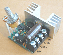 As this unit was rated at just 15 Amps maximum, Zach added another 15 Amp rated FET transistor in parallel to the output stage to raise the current capacity to 30 Amps. A fuse protects against accidental short circuits and a relay is used to control when the electrolyser is to be producing gas. The connecting wire is #12 AWG (swg 14) which has a maximum continuous current capacity of just under ten amps, so although the current peaks may be twenty amps, the average current is much lower than that. Two electromagnets outside the bubbler, positioned 2.5 inches (65 mm) above the base, are connected as part of the electrical supply to the electrolyser, and these cause most of the oxygen and hydrogen bubbles to separate and exit the bubbler through different pipes. There is a divider across the bubbler to assist in keeping the gases from mixing again above the water surface. The bubbler also washes most of the potassium hydroxide fumes out of the gas as the bubbles rise to the surface, protecting the engine as these fumes have a very destructive effect on engines. The objective with any hydroxy system is to have the minimum amount of gas between the bubbler and the engine in order to block the ignition of the gas in the unlikely event of a backfire. In this system, the gas storage tank contains a very large amount of gas, though admittedly it is not full HHO gas thanks to the electromagnet separation system, but nevertheless, it would be most advisable to have a second bubbler between the gas storage tank and the engine, positioned as close to the engine as possible. HHO gas produces a very high-speed shock-wave when it is ignited so the bubbler needs to be of strong construction to withstand this. No pop-off bubbler cap or blow-out device acts fast enough to contain a HHO shock-wave, so make the bubbler housing strong enough to withstand the pressure wave. Zach’s electrolyser arrangement is like this:  It must be realised that the water tank, electrolyser, bubbler/separator and hydrogen holding tank, all operate at thirty pounds per square inch. This means that each of these containers must be robust enough to withstand that pressure quite easily. It also means that the 30 psi one-way check valve on the oxygen venting pipe is an essential part of the design as well as being a safety feature. As a bubble of gas from the electrolyser escapes into the water tank every time a drop of water feeds to the electrolyser, the contents of the water tank above the water surface becomes a stronger and stronger mix of air and HHO. Consequently, it soon becomes an explosive mixture. It is common for static electricity to build up on a tank of this nature, so it will be very important to earth both the tank and it’s cap before removing the cap to top up the tank with more water. The electrolyser has a potassium hydroxide (KOH) solution in it. The electrolysis process produces a mixture of hydrogen, oxygen, dissolved gases (air) and potassium hydroxide fumes. When the system is being used, the water in the bubbler washes out most of the potassium hydroxide fumes, and in doing so, it gradually becomes a dilute electrolyte itself. Potassium hydroxide is a true catalyst and while it promotes the electrolysis process, it does not get used up during electrolysis. The only loss is to the bubbler. Standard practice is to pour the contents of the bubbler into the electrolyser from time to time, filling the bubbler again with fresh water. Potassium hydroxide has been found to be the most effective catalyst for electrolysis but it has a very bad effect on the engine if it is allowed to enter it. The first bubbler is very effective in removing the potassium hydroxide fumes, but many people prefer to take the scrubbing process a step further by placing a second bubbler in the line, in this instance, between the hydrogen pressure tank and the engine. With two bubblers, absolutely no potassium hydroxide fumes reach the engine. When running with HHO gas as the only fuel, it is essential to adjust the timing of the spark so that it occurs after Top Dead Centre. The timing on this bike is now set at 8 degrees after TDC. However, if David Quirey’s style of bubbling the HHO through a liquid such as acetone, then no timing alterations would be needed. This electrolyser is designed to run off the nominal six volts of a motorcycle electrics (about 7.3 volts with the engine running), but increasing the number of tubes, each containing electrode coils, would convert the design to a 12V system and then the electrolyser housing would probably be like this:  It is possible that seven sets of three or four spirals wired in parallel would be used for larger engines with their 13.8 volt electric systems. Zach uses the very simple method of allowing excess gas to be vented via the oxygen valve if gas production exceeds the requirements of the engine. When operating on a twelve volt system it might be more convenient to use a standard pressure switch which opens an electrical connection when the gas pressure rises above the value for that switch: 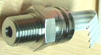 The pressure switch just mounts on one of the end caps of the pressure tank and the switch electrical connection is placed between the relay and the electrolyser. If the gas pressure reaches it’s maximum value of 30 psi. then the switch opens, stopping electrolysis until the pressure drops again:  Caution: This electrolyser is not a toy. If you make and use one of these, you do so entirely at your own risk. Neither the designer of the electrolyser, the author of this document or the provider of the internet display are in any way liable should you suffer any loss or damage through your own actions. While it is believed to be entirely safe to make and use an electrolyser of this design, provided that the safety instructions shown below are followed, it is stressed that the responsibility is yours and yours alone. An electrolyser should not be considered as an isolated device. You need to remember that both electrical and gas safety devices are an essential part of any such installation. The electrical safety devices are a circuit-breaker (as used by any electrician when wiring a house) to protect against accidental short-circuits, and a relay to make sure that the booster does not operate when the engine is not running:  However, the system designed by Zach West is almost certainly not self-sustaining and if that is correct, then the battery powering the electrolyser will need to be charged between trips. That does not have to be the situation as high-efficiency electrolysers are available. First, the Shigeta Hasebe spiral plate electrolyser (shown on page 719 of the Appendix) has produced 7 lpm of HHO gas mix for an input of just 84 watts and while that 84 watts is an inconvenient 2.8V at 30 amps, it should be possible to raise the voltage and lower the current without losing too much of the performance. In my opinion, the electrics of a motorcycle should be able to output 84 watts and so the motorcycle could become self-powered. Motorcycles can definitely become self-powered as can be seen from the electric motorcycle system of Teruo Kawai’s COP>3 design shown in chapter 2. Teruo went to America and was in a meeting aimed at getting his design manufactured and sold in America when the meeting was interrupted and Teruo intimidated into abandoning his venture. You must also remember that Steve Ryan of New Zealand demonstrated running his motorcycle on treated water. I suspect that the treated water was water which had been infused by charged water clusters as described by Suratt and Gourley later in this chapter. Their electrolyser has an efficiency of 0.00028 kilowatt-hour or less to generate one litre of gas. Those inconvenient units mean that to produce 1 lpm needs 16.8 watts or 7 lpm needs 118 watts. If cold water mist is added to the air entering the motorcycle engine, then it seems likely that a good deal less than 7 lpm would be needed. If you have a good enough tank which is made of a material capable of containing the very small molecules of this gas, then the gas can be compressed to 1000 psi and that should allow a motorcycle to run for some time on the gas cylinder. Bill Williams' DuPlex design A fully-submerged design from Bill Williams in the USA is another different style of booster:  The construction details for this booster design, can be downloaded free from here There are many other designs, including those with concentric pipes, each having its own advantages and disadvantages, some being commercially available as ready-made devices, and there are links to these boosters on the web sites mentioned above and a general booster forum and another here where people will answer any queries. One problem with the use of boosters is that if the hydroxy gas volume is higher than it needs to be, the vehicle's Electronic Control Unit ("ECU") is liable to detect the improved fuel burn and start pumping in excess fuel to offset the improved conditions. How to deal with this situation is covered in the free document which can be downloaded from here The “Hogg” Electrolyser from Selwyn Harris An interesting design is the Hogg electrolyser as described by Selwyn Harris of Australia. The Hogg cell has two stainless steel mesh electrodes coiled around each other. This gives a large electrode surface area in a very compact container. In this version of the design there are six identical cells which feed into a large bubbler. For clarity, only two of the six electrolyser cells are shown here:  The items marked with a blue dot form just one of three identical sets. That is, three filters feed out from the bottom of the bubbler, the flow through them being caused by three separate pumps and the two electrolyser cells marked “1” and “2” along with their associated pipes and four one-way valves, are replicated to give electrolysis cells “3” to “6” which are not shown in this diagram. Those three identical sets are connected to the central bubbler, spaced around it evenly at 120-degree positions horizontally as shown in rough outline here:  The water is circulated through the set of cells using three small pumps and there are two water collectors built on to the bottom of the bubbler. Also, as the ‘electrolyte’ used is rainwater, and each electrolysis cell is completely full of electrolyte as this is an ‘electrolyte circulation’ style of electrolyser. Each of the three pumps has it’s own filter to trap any particles coming from the cells as experience has shown that the water can contain a considerable amount of material. The filters are standard irrigation in-line filters made from transparent plastic filled for three quarters of their length with fine plastic sponge material. A key feature of the cell design is the use of two powerful neodymium magnets per cell. These act directly on the water and that causes a major increase in the gas production rate. The magnets have their North poles facing towards each other. The two mesh electrodes are made from stainless steel wire of 0.32 mm diameter and woven to give 2 mm holes between the wires and a 0.65 mm overall sheet thickness. These dimensions are important as other mesh sizes and styles do not give so good a performance. The electrodes are wider at one end to form a connection tab which allows easy electrical connection to each electrode and they are then wired in parallel so that each cell gets 12 volts across it as shown here:  The two mesh electrodes are cut like this:  The mesh material looks like this:  The six electrolyser cells and the single large bubbler are constructed using standard plastic plumbing materials:  The connecting pipes are a clear plastic, heat-tolerant type of 12 mm (0.5”) diameter. The bubbler is also constructed from plastic pipe fittings:  As some people have difficulty in visualising the way in which the electrodes are combined, this simplified concept sketch may be helpful:  The two electrodes are kept separated by the use of small diameter fibre washers held in place between them at strategic places using super glue. The mesh itself is then treated by being immersed in citric acid in order to make it work well with rainwater. There are three of these pairs of electrolyser cells, each pair being connected to the upper collector reservoir. The water being pumped out of each cell is passed through one of the three filters before entering the collector reservoir which feeds the small pump which keeps the water circulating which in turn keeps removing any particles which have got into the rainwater. When used with rainwater from a barrel, this electrolyser is said to draw just 1.4 amps per cell, giving a total input of about 115 watts when run on a 12-volt electrical supply. While rainwater is supposedly pure, the reality is that it seldom is and it’s ability to carry a current varies dramatically from place to place and even more widely from country to country. If you decide to build this electrolyser and find that you do not get anything like 1.4 amps flowing through any one cell, then you may well have to add a small amount of electrolyte to the water in order to get the current flowing. That is, assuming that you want a current flow of 1.4 amps per cell on 12 volts. The output of this electrolyser is said to be capable of running a small electrical generator but that has not been confirmed at this time. AVA Magnetic Levitation’s Electrolyser Adam of AVA Magnetics shows a very nicely constructed electrolyser based on an entirely different style of electrode. His video is here and his cell looks like this:  Initially built using stainless steel pipe, the electrical resistance of the long coil proved to be a problem, so Adam overcame the problem by inserting copper pipe inside the stainless steel pipe. Copper carries electrical current very well, while stainless steel has quite a high resistance to current flow, which many people find very strange, having been taught in school that all metals conduct electricity. In a coil like this, electric current has to pass through a considerable length of stainless steel in order to reach the lower turns, and that resistance to current flow is greater than the situation with an electrolyser which uses stainless steel sheets. The copper tube down the inside of the steel pipe makes a major difference because the current flows easily through the copper and then at every point along the tube, the current only needs to flow sideways through a thin layer of stainless steel in order to perform the electrolysis. The photograph above looks like a very neatly wound coil with twelve turns in it. That is not the case. It is two separate coils with turns 1, 3, 5, etc. being in one coil and turns 2, 4, 6, etc. being in the other coil. That arrangement means that each turn in the coil has a turn with the opposite voltage beside it and the electrolysis takes place between adjacent turns in the coil. The ends of each coil are sealed off carefully to prevent corrosion of the copper pipe by the electrolyte being used. Unfortunately, most of the surface area of the circular pipe electrode is not close to its neighbouring coil surface and that increased distance reduces the rate of gas production for those areas. I suspect that Adam is using a fairly dilute electrolyte in order to keep the heating effect under control and so, better performance may result when using full-strength electrolyte. However, the HHO production at around 16 amps looks impressive as shown here just before the whole container is obscured by the HHO bubbles coming off the coils:  At full power, the cell draws 18 amps when powered through a Pulse-Width Modulator manufactured by the ”HHO Powercell” company using a battery of around 12.5 volts. That 225 watts produces a gas output rate which needs to be measured. In my opinion, the gas output pipe needs to be much larger with an inner diameter of perhaps 15 millimetres as a small pipe hinders the escaping gas. If you don’t believe that, then try blowing through a length of 6 millimetre diameter plastic pipe and see how hard that is to do. Nevertheless, this is a simple, basic electrolyser with just two electrodes, although, possibly because the Pulse-Width Modulator is feeding it a good quality square wave signal, the small bubble size suggests that there is an efficiency gain which makes it perform better than would be expected. A single cell like this will find it hard to escape from the basic fact that 1.24 volts is all that is used in water electrolysis and even with the voltage drop across stainless steel you really do not want more than 2-volts between the plates. In other words, only 2-volts of the battery’s 12-volts can actually make gas and so, the vast majority of that 225 watts goes to make heat and not gas. The situation for 1, 2 or 3 single cells is like this:  It is probable that HHO production at 225 watts would be doubled if two of these cells are connected in series, that is, connected in a chain. The performance would probably be tripled at that same 18 amps of current, if three of these cells are connected in series across the voltage source. If that is done, then ideally, each cell needs to be inside its own separate container. Adam suggests that the coil produces a magnetic field which boosts the production of HHO, and considering the effect of the magnets in the Shigeta Hasebe cell, he may well be right. The arrangement with three cells connected in series and powered through a frequency-adjustable Pulse-Width Modulator would be like this, although the gas outlet pipes need to be connected together with short pipe connections as those pipes will be filled with explosive HHO when in use:  As always, the battery connects to a circuit breaker “CB” or fuse before anything else is connected. The Pulse-Width Modulator “PWM” is effectively like Dave Lawton’s most simple circuit with adjustable frequency, adjustable Mark-Space Ratio (or “Duty Cycle” as it is sometimes called), and a high output current capability. The electrical connections to the cells are done as shown in the diagram and the cells are all positioned the same way round as that allows testing with the cells leads swapped over to see if that makes a difference when the best frequency and Duty Cycle have been found. Please remember that a bubbler is essential on the gas output pipe and the depth of water in any bubbler should be at least five inches which is 125 millimetres. No measurement of the rate of HHO flow has been made. This can be measured with a cheap gas flow meter from a medical equipment supplier or a result which is easily good enough for our purposes can be determined by using a two litre or other suitable container of known capacity, filling it with water and bubbling the HHO output into the container as shown here:  The result using this method is got by timing how long it takes for the bottle to be filled with the HHO gas mixture, and from that, working out how many litres are being produced per minute. For example, if it takes one minute to fill a 2-litre bottle, then the flow rate is 2-litres per minute. If it takes two minutes to fill, then the gas output rate is 1-litre per minute. If it takes 2-minutes and 30-seconds to fill, then the rate is 0.8 litres per minute. The result will be altered slightly by the atmospheric pressure which changes from hour to hour, but we only need a rough estimate, especially if we are just comparing performance after some small change to the method of electrolysis. The video here shows methods of winding pipes into helical coils as used here and the plastic spacers needed, but the man posting, ‘ANNMANN’, has a fully equipped workshop and constructional skills not available to most experimenters. Unfortunately, he does not seem to aware of the fact that electrodes need to be very close together for the best HHO production. He has tried using marine cable (used for mast stays) instead of pipe and that is, of course, very much easier to use when making spiral electrodes, but it is probable that four spacers would be needed rather than just the two used with pipe spirals. There is also, no scope for using copper inside the hawser. Selwyn Harris of Australia, who is a very experienced HHO user, states that it is very difficult to wind stainless steel pipe into an accurate spiral. He wonders if winding the spirals using copper pipe which is very much easier to bend than stainless steel, and then electroplating the spiral with chromium, might not be a better and more practical way of producing good working spiral electrodes. For me, with my serious lack of accurate constructional skills, another much easier method of construction occurs to me. First, the arrangement of two spirals is not really effective for electrolysis as shown here:  The rate of electrolysis is directly proportional to the area of the electrodes. It is also highly affected by the separation of the electrodes. With the wires or pipes shown on the left, only a small percentage of the surface area is spaced at the best distance which your construction allows (marked by the red arrows). The two plate electrodes shown on the right have their entire surface area at the optimum spacing. So, if we are going to use pipes or wires, then we want to increase the most active surface area, and in fact, increase the electrode area overall. Working with steel is much more difficult than working with plastic, especially since most of us do not have the tools, workspace and skills to help us succeed, using marine-grade stainless steel cable is a very appealing option. This material is shown here and looks like this: 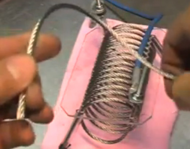 It is available from ship’s chandleries world wide and is constructed from stainless steel wires. If we use this, then we have to accept the fact that it’s electrical resistance will be high, but the big advantage is that we only have to make the plastic spacers. This brings us to the problem of increasing the surface area and decreasing the gaps between the wires. While ANNMANN has excellent video presentations, please do not be misled by the excessively large gaps which he had between his wires. The largest gap that we want is 3 millimetres, and ideally, we would like 2 millimetre gaps. So, for this I suggest that a plastic plate is drilled like this:  For this, the hole size matches your cable diameter, say, 6 mm, and the gaps between the holes are 2 millimetres if you are confident, and 2.5 or 3 millimetres if you are not confident of your skill in drilling plastic. This plate will be used to wind four nested spirals. As the cable is flexible, we need to use two additional spacer strips like this:  These are to make sure that the desired gap is maintained along all of the cable length, by threading the cable through these as each turn is made. That way, the cable is supported every quarter turn, maintaining the gap size all the way around every turn. Although only one type of cable is used, colours are used in the following diagrams merely to make it easier to see where the turns in each winding start and finish. All windings start at the bottom and end at the top. The first winding uses the innermost holes:  This winding is made with two separate lengths of cable, one shown in green and one shown in red. The lower end of the red cable terminates just this side of the plastic sheet. The lower end of the green cable terminates just beyond the other side of the plastic sheet. Unlike the diagram, the cable is NOT cut off short as shown but is left long so that it can be connected outside the plastic cell container. We now double the electrode surface area by winding a second pair of coils just outside the first one. The arrangement looks like this:  This second layer is wound in exactly the same way as the previous one. The outer cable turns are not exactly above the spiral turns underneath, but they are very close to being directly above. When we connect the cables electrically, we arrange for the cables surrounding any cable to be the opposite polarity, so that the electrolysis is maximised. The next step is to wind the third layer:  And then the fourth layer is wound using the remaining holes:  Connected electrically as shown, every cable in the first and fourth layers is surrounded on three side with cables of opposing polarity. The cables in layers two and three have every turn surrounded on all four sides by cables of the opposing polarity. So, this arrangement has overcome the need for difficult pipe bending, has increased the electrode area considerably and has achieved a reasonable gap between the electrodes and has improved the area of best electrolysis by 87%. We now improve matters considerably by using three of these cells in series in order to use the applied power more efficiently. There is, of course, no reason why there should not be more than three of these cells in series and I would expect five to be the likely maximum due to excessive voltage drop across the stainless steel cable. There is also no reason why there should not be five or more spiral layers in each cell and each additional layer raises the overall efficiency of that set of spirals. However, while it seems very probable that this construction would yield a good performance, please remember that this is only a suggestion and at time of writing, it has not been built and tested. When first testing the unit, the Pulse-Width Modulator is set to give a low to medium current flow through the cells. Then the frequency control is used to get the maximum gas output without altering the current setting. If the current drops at the point of peak gas production during this test, that is not a problem. With multi-layer spirals of this type, a gas outlet pipe of 20 millimetres would be recommended. Also, the gas outlet should have a baffle plate across it to prevent tiny droplets of electrolyte escaping with the gas, as shown elsewhere in this chapter. That should be done even if the electrolyser is to be used in a stationary location such as feeding a generator. Electrical connections to the ends of the spiral wires can be made with large screw connectors not unlike the ordinary hardware store type but intended for much larger wires. These are also available through ship’s chandlers as boats often use high-current twelve volt wiring of large diameter. Advanced DC Boosters All of the practical construction details on electrical safety, gas safety, engine connections, type of water, safe mixing of electrolyte, etc. already discussed, apply to all kinds of electrolysers and boosters of every design. So, please understand that these are universal features which need to be understood when using any design of booster. It is possible to produce large volumes of hydroxy gas from a DC booster, enough gas to run a small motor directly on it. For this, we need to pay attention to the efficiency factors already covered in this document. The person who is outstanding in this field is Bob Boyce of the USA who has kindly shared his experience and expertise freely with people who want to use serious electrolysers. Bob's attention to detail when constructing high-performance electrolysers has resulted in efficiencies which are more than double those of the very famous Michael Faraday whom most scientists consider to be the final word on electrolysis. We are now moving from the "casual" style of booster to the "serious" style of electrolyser. In this category, you will find that the units built are not cheap, weight a considerable amount, require considerable skill to make and usually are quite large physically. I will mention two designs here. First, the very well-known design from Bob Boyce. For this electrolyser, Bob makes solid stainless steel electrode plates act as cell partitions as well as being electrodes. This is a clever technique but it takes a very high level of construction accuracy to make a box with slots in the side and base, so that the stainless steel plates can be slid into the box and when there, form a watertight seal between the cells, preventing electrical current bypassing the places by flowing around them. The number of cells in the electrolyser depends on the electrical DC voltage supply which is produced from the electrics of the vehicle. This higher voltage is created by using a standard off-the-shelf "inverter" which produces high-voltage alternating current ("AC") meant to be the equivalent of the local electricity mains supply. In the USA, the voltage produced is in the 110 to 120 volt region, elsewhere, it is in the 220 to 230 volt region. If you are not familiar with electrical jargon, then check out chapter 12 which explains it step by step. The AC output from whatever inverter you buy, is changed back into DC by using a component called a "diode bridge" and a reservoir device called a capacitor. When this is done, the resulting DC voltage is 41% greater than the quoted AC voltage, so a 110-volt inverter will produce about 155 volts and a 220-volt inverter about 310 volts. As you want about 2 volts per cell, the number of cells would be about 80 or 150 depending on which inverter is used. This large number of stainless steel plates each sized at six-inches (100 mm) square, creates a substantial weight which then is increased by the weight of the case, and the electrolyte. The overall arrangement (without the capacitor) is like this:  A very high-precision box for this style of electrolyser can be made from the design of Ed Holdgate of Florida if you are a skilled fabricator:  The gas production rate is so high that the gas outlet pipe has to have holes drilled along the top in order to try to exclude spray and moisture from the massive rate of bubbles bursting at the surface of the electrolyte. The high efficiency of Bob's electrolysers is due to his meticulous preparation and construction methods. You will notice that Bob recommends the use of a particle filter with a 1-micron mesh, between the engine and the hydroxy system. Apart from ensuring that everything entering the engine is very clean, the particle filter with a mesh of that small size, also acts as a flashback-preventer as flame can't pass through it. Firstly, the stainless steel plates are cross-scored with sandpaper to create a specially shaped plate surface which helps high-speed bubble release. Secondly, the plates are put through a rigorous "cleansing" process where they are subjected to repeated periods of electrolysis followed by rinsing particles off the plates and filtering the electrolyte solution. When no further particles break free from the plates, they are then put through a "conditioning" process which develops a catalytic layer on the plate surfaces. This processing and the various construction details are provided in the following free download document, thanks to Bob's generosity in sharing his experience with us here and there is a forum for Bob's design here where questions are answered. Bob Boyce is a most experienced and knowledgeable series-cell designer, and sincere thanks are due to him for sharing his design freely with everybody and for his continuous help, advice and support of the builders of electrolysers. Bob achieves a massively increased gas production rate by using an electrolyser with a large number of cells in it. Bob’s electrolyser is easily the most effective available at this time. It uses one hundred cells (101 plates) and applies a sophisticated pulsing waveform which raises the operational efficiency far above that envisioned by the science textbooks available today. Units with just 60 cells are inclined more to brute-force DC electrolysis, tending to mask the gains produced by pulsing. As there is a voltage drop across each stainless steel electrode plate, it is usual to allow about 2 volts across each cell for DC operation. However, Bob finds that for high-efficiency pulsing, the optimum voltage for each cell with 316L-grade stainless-steel electrode plates is about 1.5 volts. This means that a voltage of about 1.5 x 100 = 150 volts is needed to power it to its maximum pulsed output. To get this higher voltage, Bob uses a 110 Volt inverter. An inverter is a common, commercially available electronic circuit which usually has a 12 Volt DC input and generates a 110 Volt AC output. These are readily available for purchase as they are used to run (US) mains equipment from car batteries. The output from the inverter is converted from Alternating Current to pulsing Direct Current by passing the output through four diodes in what is called a ‘Diode Bridge’. These are readily available at very low cost from electronic component suppliers. Obviously, it would not be practical to use a hundred self-contained cells daisy-chained together to act as the series-connected electrolyser cell. There would not be enough physical space in the engine compartment for that, so a different style of cell construction is needed. The view looking down on several separate electrolyser cells could be represented something like this:  Here the plus side of each cell is connected to the minus side of the next cell to provide a set of six interconnected cells acting in series. The current flowing through the electrolyser goes through each cell in turn and so each cell receives exactly the same current as the other cells. This is the same sort of arrangement as using six self-contained cells in a daisy-chain. To reduce the physical size of the unit, it is possible to construct the electrolyser as shown here:  In this arrangement, the individual cells have just one positive plate and one negative plate. The plates slot into the sides and bottom of the housing so that the electrolyte is trapped between the plates and an air gap is formed between the plus plate of one cell and the minus plate of the next cell. These air gaps are wasted space. They contribute nothing to the operation of the electrolyser. Each consists of a metal plate, a gap and a wire connection to the next metal plate. From an electrical point of view, the two metal plates at the opposite ends of these gaps, being connected by a wire link, are effectively the same plate (it is just a very thick, hollow plate). These air gaps might as well be eliminated which would save one metal plate and one wire link per cell. This can be difficult to visualise, but it produces an arrangement as shown here:  The only air gaps remaining are at the ends of the electrolyser. The plates in the middle are notionally touching each other. The positive plates are marked in red and the negative plates are shown in blue. In reality, there is only one metal plate between each cell and the next cell - the red and blue marking is only a notional device to try to make it easier to see that the diagram actually shows six separate cells in a single housing. They are separate cells because the metal electrode plates extend into the base and sides of the housing, thus isolating the six bodies of electrolyte from each other. It is very important that the different bodies of electrolyte are fully isolated from each other, otherwise the electrolyser will not act as a series-connected unit and most of the current will skip past the middle plates and just run from the first plate to the last plate around the sides of the other plates. So, the plates need to be a fairly tight push-fit in grooves cut in the sides and base of the housing. The electrolyte level must always be below the top of the plates as shown here:  An electrolyser with a hundred cells, built in this style will have 101 metal plates and 100 separate bodies of electrolyte. In spite of these large numbers, the size of the overall unit does not have to be excessive. The spacing between the plates is set to, say, 3 mm (1/8 inch) and the plate thickness might be 16 gauge (1/16 inch), so the width of a 100-cell electrolyser is about 20 inches. In actual practice, the gaps at the end of the electrolyser may also contain electrolyte although that electrolyte takes no part in the electrolysis process. The size of the plates may be determined by the space available in the engine compartment. If there is a large amount of spare space, then the plate size may be selected by allowing from two to four square inches of area on both sides of each plate, per amp of current. Each side of every plate is in a different electrolysis cell so a 6-inch by 6-inch plate will have 36 square inches on each face and so would carry between 36 / 4 = 9 to 18 amps of current. The choice of current is made by the builder of the electrolyser and it will be influenced by the size and cost of the inverter chosen to drive the electrolyser and the allowable current draw from the battery. This is for straight DC electrolysis where the battery is connected directly across the electrolyser. Using Bob’s triple-oscillator electronics pulser card, the electrolyte level has to be kept down to about three inches from the top of the six inch plate because the gas production rate is so high that there has to be substantial freeboard to stop the electrolyte being splashed all over the place. Bob usually uses a 6” x 6” plate size. It is essential that every item which contains HHO gas is located outside the passenger compartment of any vehicle. Under no circumstances should the electrolyser or bubbler be located in the passenger area of the vehicle, even if pop-off caps are provided and a second protective outer housing is provided, as the explosive force is so great that permanent hearing damage would be a serious possibility. For straight DC operation of an electrolyser of this type, the circuitry is very straightforward. The inverter should be mounted securely, preferably in the stream of air drawn in to cool the radiator. Using a diode “bridge” of four diodes converts the stepped up AC output of the inverter back into pulsing DC and produces the electrical arrangement shown here: As mains voltage is quoted as an average figure (“root-mean-square”) it has a peak voltage of 41% more than that. This means that the pulsing DC has a voltage peak of just over 150 volts for the nominal 110 volt AC output from the inverter. The one-way valve shown between the two bubblers, is to prevent the water in the bubbler mounted beside the electrolyser, being driven into the electrolyser in the event of an explosion in the bubbler mounted beside the engine. The bubblers and the particle filter remove all traces of electrolyte fumes from the gas as well as protecting against any accidental igniting of the gas caused by the engine misfiring. The very famous Michael Faraday who was an exceptionally gifted experimenter, placed two electrodes in water and determined how much gas was produced per amp of current. Using an electrolyte and recent tenchology when running on DC, Bob Boyce would not consider an electrolyser properly constructed, cleansed and conditioned until it was producing more than double Faraday’s gas production rate. A typical working electrolyser made by Bob would have about 216% of Faraday’s result. People taught in universities and unaware of current technology, use Faraday’s result in calculations and those calculations indicate that it would take more energy to produce HHO gas than could be produced by then burning the hydrogen produced. Their calculations are wrong. The energy in freshly made HHO gas is typically four times more energetic than hydrogen is and so those calculations are too low by a factor of more than eight times. Also, the majority of energy from burning HHO comes from “charged water clusters” (see chapter 10) and not from the hydrogen, and most of these good people doing the calculations have never even heard of charged water clusters, and so, they accept the “can’t be done” verdict without thinking about it. Pulsed Operation If you have already read chapter 10, you will know that the next step forward in raising HHO production is to apply a suitable pulsed waveform to the electrolyser terminals rather than just a straight DC voltage. Doing this with the design of Bob Boyce raises the cell efficiency to around ten times the result produced by Michael Faraday. Bob Boyce’s highly efficient pulsed electrolysis system has been very generously shared freely by Bob so that anyone who wishes may construct one for their own use without the payment of a licence fee or royalties. Just before presenting the details, it should be stressed that in order to get Bob’s performance of up to 1,000% of the Faraday (supposed) maximum gas output, each step needs to be carried out carefully exactly as described. Much of the following text is quoted from Bob’s forum posts and so should be considered as his copyright, not to be reproduced without his permission. Your Responsibility: If you decide to construct an electrolyser of this, or any other design, you do so wholly on your own responsibility, and nobody is in any way liable for any loss or damage, whether direct or indirect, resulting from your actions. In other words, you are wholly responsible for what you choose to do. I say again, this document must not be construed as an encouragement for you to construct this or any other electrolyser. Bob’s electrolyser splits water into a mixture of gases, mainly hydrogen and oxygen. That gas mixture, which will be referred to as “HHO” is highly explosive and must be treated with respect and caution. A fairly small volume of HHO gas exploded in air is quite liable to cause permanent hearing loss or impairment due to the shock waves caused by the explosion. If HHO gas is ignited inside a sealed container, then the resulting explosion is liable to shatter the container and propel shrapnel-like fragments in all directions. These fragments can cause serious injury and every precaution must be taken to ensure that an explosion of that nature never happens. Bob uses two bubblers and a one-way valve to protect against this occurrence, and details of these are given in this document. To make the water inside the electrolyser carry the necessary current, potassium hydroxide (KOH) is added to distilled water. This is the best electrolyte for an electrolyser of this type. Potassium hydroxide is also known as “caustic potash” and it is highly caustic. Consequently, it needs to be handled carefully and kept away from contact with skin, and even more importantly, eyes. If any splashes come in contact with you, it is very important indeed that the affected area be immediately rinsed off with large amounts of running water and if necessary, the use of vinegar which is acidic. This electrolyser design uses a toroidal transformer to interface the electronics to the electrolyser cells. It is vital that this transformer be used very carefully. Under no circumstances may this transformer be powered up by the electronics when connected to anything other than the filled electrolyser cells as they act as a safety buffer. When driven by Bob’s electronics, this transformer draws additional energy from the environment. While this is very useful for electrolysis, there are sometimes unpredictable energy surges which can generate as much as 10,000 amps of current. If one of these should occur when the transformer is not connected to the electrolyser which is able to soak up this excess, the resulting electrical conditions can be very serious. If you are lucky, it will just burn out expensive components. If you are not lucky, it can cause a lightning strike which is liable to hit you. For that reason, it is absolutely essential that the toroid transformer is never powered up with the secondary winding connected to anything other than the filled electrolyser. Patenting: It should be clearly understood that Bob Boyce, has released this information into the public domain and it has been displayed publicly since early in 2006. It is not possible for any part of this information to be made part of any patent application anywhere in the world. This prior public disclosure of the information prevents it being patented. It is Bob’s intention that this information be freely available to people world-wide. It should also be emphasised that all of the quotations of Bob’s words which is a very extensive part of this document, remain the copyright of Bob and may not be reproduced for display or sale without his prior written permission. The Objective: This is a “HHO-On-Demand” (“HOD”) system. It is very difficult indeed to generate HHO gas fast enough to power an internal combustion engined vehicle under all road conditions. Moving from standstill to rapid acceleration causes such a massive sudden requirement for additional volumes of HHO gas, that it is difficult to provide that volume instantly. A better solution is to use an electric engine for the vehicle. This can be an electric vehicle which was designed from scratch as such, or it can be a standard vehicle which has been adapted for electric engine use. These electric vehicles are usually limited in how far they can travel, but a good solution to this is to use an electrical generator to charge the batteries, both when the vehicle is in use and when it is parked. This electrolyser can be used to run such a generator on water as shown in chapter 10. With this arrangement, there are no CO2 emissions and the vehicle is very environmentally friendly. The batteries provide the necessary sudden acceleration demands and the generator recharges the batteries during normal driving. Overview: Bob’s pulsed system has the following components:
Building the Case: The case needs to have very accurate slots cut in it. If you do not have a milling machine, then you might consider getting a fabrication shop to mill the slots for you. The case has two ends, two sides, one base and one lid. Of these, the two sides and the base need 101 accurate grooves cut in them. The grooves are there to hold the electrode plates securely in position, and have to be cut extremely accurately. The groove width is set at 0.0003" less than the actual, measured plate thickness. This prevents any electrical flow around the plates. If you do not have the equipment to do this, then there is an enthusiast who is willing to do the cutting for people in the USA (and possibly elsewhere) at reasonable price. Many people ask about moulding the slotted sides but this is physically impossible to do to the accuracy needed and the cell performance depends on plate spacing to very high accuracy and slot width to even higher accuracy. This is not a backyard construction quality job and there are very, very few people with both the equipment and skill to complete the construction to this degree of accuracy.  The base and two sides of the cell could have grooves cut in them to take the plates. This is not a good idea for various reasons, including the fact that the steel plates expand when they warm up and are liable to crack the acrylic case unless the slots are cut deeper than normal. Also, it is difficult to cut very accurate slots in acrylic due to the heat of the cutting blade causing the acrylic to deform in the immediate area. Grooved acrylic is very much weaker and breaks easily due to the planes of weakness introduced into the material. Using Ultra High Molecular Weight Poly Ethylene or High Density Poly Ethylene (food chopping-board material) strips is a much better technique as that material does not have the same cutting heat problem and it can also take the plate expansion much better, so it is the construction method of choice. It is also a cheaper material. The grooves which are cut for the plates should be three thousandths of an inch wider than the thickness of the plates. A good plate thickness is 16 gauge sheet which is one sixteenth of an inch thick or 0.0625 inch (1.5875 mm), so the recommended groove width for that is 0.0655 inches which is not a convenient fraction being about four and one fifth sixty-fourths of an inch. The grooves are 1/8” (3 mm) deep. The supplier of the acrylic sheet needed for making the case, will be able to supply “glue” specifically designed for joining acrylic sheets together. This glue actually welds the plates together so that the sheets become one continuous piece of acrylic along the joint. Start by mating the sides and the base. Insert two or three plates into the slots to be quite sure that the alignment is spot-on during the joining process. Line the ends up during jointing to be sure that the sides are completely square when being joined to the base. Concerns have been expressed about the strength of the acrylic casing under severe road conditions. So it has been suggested that the acrylic components be constructed from sheet which is 3/4” to 1” thick (18 mm to 25 mm) and the corners reinforced with angle iron secured with bolts tapped into the acrylic as shown below.   Here is a photograph of a 101-plate housing built by the late Ed Holdgate who worked to a very high standard of accuracy : 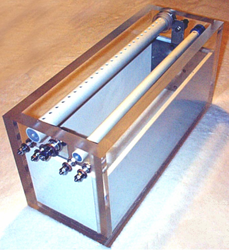 This housing looks very simple and straightforward, but this is highly misleading and the materials are very expensive, so any error is costly. The construction accuracy needed is very high indeed with many opportunities for a total and expensive disaster. Ed Holdgate has built several custom fixtures to ease the construction, but construction is still very difficult even with these specialist fittings and his years of experience. "Sikaflex 291" or "Marine Goop" marine bedding compound can be used to seal between the two slotted sides and the slotted base, and between the slotted sides and the two end inserts, in order to prevent any leakage between the acrylic and any of these inserts. The accuracy required for the slots to hold the stainless steel plates is 0.0003” and the plates are tapered with a belt sander on both sides along all four edges so that when they are forced into the slots they will not cut into the sides of the slots. This produces excellent leakage characteristics, but don’t lose sight of the very high accuracy of the slot cutting needed for this. The edges of the slotted inserts receive a bead of Sikaflex marine bedding compound attaching them to the acrylic box and the compound is allowed to cure before construction is continued. The end plates with the stainless steel straps welded to them are used to connect the electrical supply to the plates, keeping any connection which could possible work loose and cause a spark, completely outside the housing. Even though the straps are welded and there is no likelihood of them coming loose, the welds are still kept below the surface of the electrolyte. Getting and Preparing the Plates: A set of 101 plates is needed for the electrolyser. The material used when making the plates is very important. It should be 16-gauge 316L-grade stainless steel as it contains a blend of nickel and molybdenum in the correct proportions to make it a very good catalyst for the pulsing technique. You can try your local steel stockists to see if they can supply it and what their charges would be. One satisfactory stainless steel supplier which Bob has used is Intertrade Steel Corp., 5115 Mt. Vernon Rd SE, Cedar Rapids, IA 52406. Do not buy from eBay as you have no real comeback if the plates supplied are dished due to having been flame cut. It is very important indeed that when asking for a quote that you make sure that the supplier is aware of the accuracy you require. The plates need to be flat to a tolerance of +/- 0.001 inch after cutting and this is the most important factor. That level of accuracy excludes any kind of flame cutting as it produces inevitable heat distortion. With shearing, expect +/- 0.015 inch on the cuts and +/- 0.001 inch on flatness. Laser cutting produces much higher accuracy and you can expect as good as +/- 0.005 inch on cuts and there is no spec needed for flatness since laser cutting does not distort the edges like shearing does. The plates are square: 6 inches by 6 inches, but that does not represent 36 square inches of active surface area as some plate area is inside the grooves and some of each plate is above the surface of the electrolyte. Another point to remember is that 101 steel plates this size weigh a considerable amount and the completed electrolyser with electrolyte in it will weigh even more. It is essential therefore to have a case which is strongly built from strong materials, and if a mounting bracket is to be used, then that bracket needs to be very robust and well secured in place. The preparation of the plates is one of the most important steps in producing an electrolyser which works well. This is a long task, but it is vital that it is not skimped or hurried in any way. Surprisingly, brand new shiny stainless steel is not particularly suitable for use in an electrolyser and it needs to receive careful treatment and preparation before it will produce the expected level of gas output. The first step is to treat both surfaces of every plate to encourage gas bubbles to break away from the surface of the plate. This could be done by grit blasting, but if that method is chosen, great care must be taken that the grit used does not contaminate the plates. Stainless steel plates are not cheap and if you get grit blasting wrong, then the plates will be useless as far as electrolysis is concerned. A safe method which Bob much prefers is to score the plate surface with coarse sandpaper. This is done in two different directions to produce a cross-hatch pattern. This produces microscopic sharp peaks and valleys on the surface of the plate and those sharp points and ridges are ideal for helping bubbles to form and break free of the plate. Bob Boyce uses a specially widened 48-inch belt sander which is good for preparing the plates using 60 or 80 grit. However, most people don’t have this equipment and do the sanding by hand. Bob stresses that when doing hand sanding the sandpaper is drawn across the plates in one direction only and not backwards and forwards, as the backwards stroke always destroys the perfectly good ridges created on the forward stroke. Also, you only need two strokes in one direction before turning the plate through ninety degrees and completing the sanding of that face of the plate with just two more strokes (again, with no backstroke). Most people want to sand the plates far too much and if overdone to a major degree, that can reduce the plate thickness and cause electrolyte leakage through the slots around the plates. So, to say it again, to sand one face of a plate, use just two strokes in one direction, turn the plate through ninety degrees and finish that face with just two more strokes, both in the same direction. Always wear rubber gloves when handling the plates to avoid getting finger marks on the plates. Wearing these gloves is very important as the plates must be kept as clean and as grease-free as possible, ready for the next stages of their preparation. Any particles created by the sanding process should now be washed off the plates. This can be done with clean tap water (not city water though, due to all the chlorine and other chemicals added), but only use distilled water for the final rinse. A point which is often missed by people constructing electrolysers is the fact that electrolysis is not just an electrical process, but it is also a magnetic process. It is important for maximum operating efficiency that the plates are aligned magnetically. In theory, stainless steel is not magnetic, but much of the stainless steel actually supplied to builders is slightly magnetic. When the plates arrive from the supplier each plate may have random magnetic characteristics. The easiest way to deal with this situation is to try to give the plates a mild magnetic orientation. This can be done quite simply by wrapping a few turns of wire around the stack of plates and passing some brief pulses of DC current through the wire.  Obviously, the plates need to be kept in the same direction when being slotted into the case. The next step in the preparation process is to make up a weak solution of potassium hydroxide. This is done by adding small amounts of the potassium hydroxide to water held in a container. The container must not be glass as that is not a suitable material in which to mix the electrolyte. Potassium hydroxide, also called KOH or “Caustic Potash”, which can be bought from various suppliers such as: www.essentialdepot.com www.organic-creations.com www.nuscentscandle.com While Potassium hydroxide (KOH) and Sodium hydroxide (NaOH) are the very best electrolytes, they need to be treated with care. The handling for each is the same: Always store it in a sturdy air-tight container which is clearly labelled "DANGER! - Potassium Hydroxide". Keep the container in a safe place, where it can’t be reached by children, pets or people who won't take any notice of the label. If your supply of KOH is delivered in a strong plastic bag, then once you open the bag, you should transfer all its contents to sturdy, air-tight, plastic storage containers, which you can open and close without risking spilling the contents. Hardware stores sell large plastic buckets with air tight lids that can be used for this purpose. When working with dry KOH flakes or granules, wear safety goggles, rubber gloves, a long sleeved shirt, socks and long trousers. Also, don’t wear your favourite clothes when handling KOH solution as it is not the best thing to get on clothes. It is also no harm to wear a face mask which covers your mouth and nose. If you are mixing solid KOH with water, always add the KOH to the water, and not the other way round, and use a plastic container for the mixing, preferably one which has double the capacity of the finished mixture. The mixing should be done in a well-ventilated area which is not draughty as air currents can blow the dry KOH around. When mixing the electrolyte, never use warm water. The water should be cool because the chemical reaction between the water and the KOH generates a good deal of heat. If possible, place the mixing container in a larger container filled with cold water, as that will help to keep the temperature down, and if your mixture should “boil over” it will contain the spillage. Add only a small amount of KOH at a time, stirring continuously, and if you stop stirring for any reason, put the lids back on all containers. If, in spite of all precautions, you get some KOH solution on your skin, wash it off with plenty of running cold water and apply some vinegar to the skin. Vinegar is acidic, and will help balance out the alkalinity of the KOH. You can use lemon juice if you don't have vinegar to hand - but it is always recommended to keep a bottle of vinegar handy. Plate Cleansing: Plate cleansing is always done with NaOH. Prepare a 5% to 10% (by weight) NaOH solution and let it cool down. A 5% solution ‘by weight’ is 50 grams of NaOH in 950 cc of water. A 10% solution ‘by weight’ is 100 grams of NaOH in 900 cc of water. As mentioned before, never handle the plates with your bare hands, but always use clean rubber gloves. Put the sanded and rinsed plates into the slots in the electrolyser case, keeping them all the same way round so that they remain magnetically matched. Fill the electrolyser with the NaOH solution until the plates are just covered. A voltage is now applied across the whole set of plates by attaching the leads to the outermost two plates. This voltage should be at least 2 volts per cell, but it should not exceed 2.5 volts per cell. Maintain this voltage across the set of plates for several hours at a time. The current is likely to be 4 amps or more. As this process continues, the boiling action will loosen particles from the pores and surfaces of the metal. This process produces HHO gas, so it is very important that the gas is not allowed to collect anywhere indoors (such as on ceilings). After several hours, disconnect the electrical supply and pour the electrolyte solution into a container. Rinse out the cells thoroughly with distilled water. Filter the dilute NaOH solution through paper towels or coffee filters to remove the particles. Pour the dilute solution back into the electrolyser and repeat this cleaning process. You may have to repeat the electrolysis and rinsing process many times before the plates stop putting out particles into the solution. If you wish, you can use a new NaOH solution each time you cleanse, but please realise that you can go through a lot of solution just in this cleaning stage if you choose to do it that way. When cleansing is finished (typically 3 days of cleansing), do a final rinse with clean distilled water. It is very important that during cleansing, during conditioning and during use, that the polarity of the electrical power is always the same. In other words, don’t swap the battery connections over as that destroys all the preparation work and requires the cleansing and conditioning processes to be carried out all over again. Plate Conditioning: Using the same concentration of solution as in cleansing, fill the electrolyser with dilute solution up to 1/2" below the tops of the plates. Do not overfill the cells. Apply about 2 volts per cell and allow the unit to run. Remember that very good ventilation is essential during this process. The cells may overflow, but this is ok for now. As water is consumed, the levels will drop. Once the cells stabilise with the liquid level at the plate tops or just below, monitor the current draw. If the current draw is fairly stable, continue with this conditioning phase continuously for two to three days, adding just enough distilled water to replace what is consumed. If the solution changes colour or develops a layer of crud on the surface of the electrolyte, then the cell stack needs more cleansing stages. Do not allow the cells to overfill and overflow at this point. After two to three days of run time, pour out the dilute KOH solution and rinse out the electrolyser thoroughly with distilled water. Cell Operation: Mix up a nearly full-strength solution of potassium hydroxide (280 grams of KOH added to 720 cc of water) as it is 20% more effective in use than is sodium hydroxide. The filling of the electrolyser depends on whether straight DC electrolysis is to be used, or resonant electrolysis is to be used. For straight DC electrolysis, fill the electrolyser to about one inch below the tops of the plates. The DC voltage applied to the electrolyser will be about 2 volts per cell or a little less, so this 100-cell electrolyser will have 180 to 200 volts applied to it. This voltage will be generated with an inverter. For resonant operation, fill the electrolyser to only half the plate height because the HHO gas production is so rapid that room has to be left for the gas leaving the plates. With resonant operation, about 1.5 volts per cell is used. Troubleshooting:
Resonant operation of the electrolyser requires the use of a DC pulsing system. Bob has designed an advanced system for this, consisting of a sophisticated electronics board and a finely-tuned toroidal transformer which interfaces and matches the electronics to the electrolyser. These are available in kit form from The Hydrogen Garage in America and these electronics boards produce three separate frequencies which are combined together to give a rich and complex output waveform further modified by the toroidal transformer:  In Bob’s electrolyser build, those frequencies were about 42.8 KHz, 21.4 KHz and 10.7 KHz but please don’t get the wrong impression here, there is no single exact frequency or set of frequencies which should be used. The size and shape of your cell, the electrodes spacings, electrolyte density, electrolyte temperature and operational pressure are all factors which affect the tuning of the electronics. With Bob’s large marine-duty cells with square twelve-inch plates, he found the base resonance point using his original, modified inverter, to be at least 100 Hz lower than that of the prototypes with smaller plate sizes. The triple-oscillator board can be tuned with an oscilloscope but if one is not available, then the preset resistors are set to their mid-point and then the 42,800 Hz frequency is adjusted very slowly to find the point of maximum gas output. This is a very precise point and it is essential to use high-quality preset resistors which vary their resistance very accurately. The aim is to adjust the frequency by as little as 1 Hz at a time. When the optimum point is found, then the procedure is repeated with the 21,400 Hz frequency generator, and finally the 10,700 Hz frequency adjustment. Last of all, the Mark/Space ratio presets are adjusted to give the lowest pulse width which does not reduce the rate of gas generation. When he tried separate flooded cells connected in series, he was not able to get anything more than a marginal rise in performance over a broader range. He felt that this was due to each cell in the set having a slightly different resonant point which did not match very well with the other cells. Bob had to go to the series plate design with accurate spacing and tight tolerance on slots and plates in order to get the resonant responses to line up on all cells. Also, he found that some choices of electrolyte would not produce resonance at any frequency, though he is not sure why. Some worked well while others worked marginally, so Bob stuck with what worked the best for him - sodium hydroxide (NaOH) and potassium hydroxide (KOH). It needs to be stressed here, that every electrolyser build is slightly different from all others, even though they may have been meant to be exactly the same. There will be small differences between the plates in one electrolyser and the plates in other electrolysers. The electrolyte concentration will be slightly different, the plate preparation will be slightly different and the overall magnetic characteristics will be unique to each actual build. For that reason, the tuning of the completed electronics board and the construction of the best possible transformer to match the electronics to the electrolyser, is always different for each electrolyser built. The completed third-generation Boyce board looks like this: 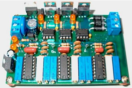 It is not too difficult to assemble this board as the printed circuit board can be purchased ready-made and a complete set of components can be ordered using the ordering system set up in the WorkingWatercar forum. 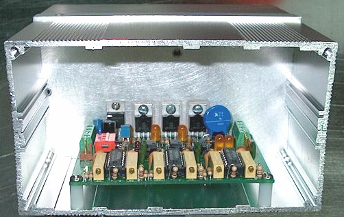 You should notice here, that the whole of the aluminium case is being used as a “heat-sink” to dissipate the heat generated in the FET driver transistors. These transistors are all bolted to the case and each has it’s own rectangle of mica “washer” between the transistor and the case. These pieces of mica pass heat very readily to the case, while at the same time, isolating the transistors electrically so that they will not interfere with each other. Notice too, the plastic support columns at each corner of the printed circuit board. These are used to mount the printed circuit board securely, while holding it away from the metal case and so preventing any possibility of the connections on the underside of the board being short-circuited by the case itself. In some of the builds of the electronics board, it has been found that it is sometimes difficult to get the highest frequency oscillator operating correctly at around 42.8 KHz due to some NE556 chips being out of specification. Even though they should be the same, chips from different manufacturers, and even the same branded chip from different suppliers, can have slightly different actual specifications. On both the PWM3E and PWM3F boards, C4 has now been changed from 0.1 microfarad back to 0.047 microfarad to accommodate the corrected specs of the newer Texas Instruments NE556N chip (the one marked with MALAYSIA on top). The earlier versions of the NE556N chip had required a change to 0.1 microfarad to correct for specifications that were sub-standard. Depending on which chip you actually use in the “U1 - U3” board positions, you may have to adjust the value of C1, C3, and C4 to compensate for variations from the original 556 chip specification, or adjust some of the other timing component tolerances. The TAIWAN and other marked Texas Instruments chips will still work ok in the “U2” and “U3” locations, but there has been a big issue sourcing chips that will reach 43 kHz in the “U1” location. The MALAYSIA chips tested so far have been satisfactory. Setting up the completed board: Jumper J1: If this is short-circuited it disables all three Pulse-Width Modulators, for oscillator outputs only. Jumper J2: If this is short-circuited it connects the MOSFET Gate Supply TB3 to +DC for a single supply. Jumper J3: If this is short-circuited it connects the MOSFET Source to -DC for a common ground. Jumper J4: If this is short-circuited it enables the input of the Auxiliary TTL Inputs 1, 2 and 3. This is a convenient test point for measuring the outputs of each of the three signal generator stages. To enable the auxiliary inputs, the on-board generators must be disabled with SW1 switches 1, 2 and 3 as shown here: Switch SW1: switching 1 on disables the Pulse-Width Modulation of oscillator 1 switching 2 on disables the Pulse-Width Modulation of oscillator 2 switching 3 on disables the Pulse-Width Modulation of oscillator 3 switching 4 on disables the Pulse-Width Modulation of all three oscillators  This board has been superseded Terminal Block TB1: is the DC Power Input & MOSFET Source Ground Terminal Block TB2: is the MOSFET Drain/PWM Outputs & MOSFET Gate Supply Input  This board has been superseded In more detail: J1 is for the connection of an optional external control or safety shutdown device, such as a pressure or temperature limit switch. J1 is shorted to shut down waveform generation. For normal operation, J1 is left open. J2 and J3 are for optional voltage modification support. For normal operation, both J2 and J3 are shorted with 2 position jumper shorting blocks. J4 is for the connection of optional auxiliary inputs. For normal operation, nothing is connected to J4. J4 can also be used to connect an oscilloscope to view the Pulse-Width Modulator generator waveforms of channels 1, 2, and 3. SW1 is for disabling PWM generator channels 1, 2, and 3 via switches 1, 2, and 3. Switch 4 is a master disable that turns off all 3 channels. For normal operation, all 4 switches are switched OFF. Terminal Block TB1 has 4 connections as follows: 1. DC Input + is connected to the 13.8 V DC power supply positive connection via a 2-amp fuse or circuit breaker. 2. DC Input - is connected to the 13.8 V DC power supply negative connection. If a shorting plug is installed at J3, this wire is optional. 3. and 4. Ground is connected to the 13.8 V DC power supply negative connection via heavy gauge wire. There are two wire connection terminals available so that two equal length wires may be used to reduce wire resistance losses. Terminal BlockTB2 has 4 connections which are connected as follows: Gate + is not normally connected when a shorting plug is installed at jumper J2. Output 1 is connected to the “cold” side of primary 1 of the toroidal transformer. Output 2 is connected to the “cold” side of primary 2 of the toroidal transformer. Output 3 is connected to the “cold” side of primary 3 of the toroidal transformer. The “hot” sides of primaries 1, 2, and 3 are brought together, and connected to the 13.8 V DC power supply positive connection via heavy-gauge wire and a 60-amp fuse or DC circuit-breaker. Note: These fuses are for short circuit protection, and are not an indication of system power consumption. Testing the completed board: Do NOT connect the PWM3F outputs to a powered transformer until after the unit tests show it to be fully functional. You may pull the 60-amp fuse out, or trip the DC circuit-breaker, while testing and tuning. Power up the PWM3F board and check the indicator LEDs for proper operation: LED 1 - the Channel 1 output - should be lit in normal operation, off if disabled. LED 2 - the Channel 2 output - should be lit in normal operation, off if disabled. LED 3 - the Channel 3 output - should be lit in normal operation, off if disabled. LED 4 - the PWM channel 1 disable - should be off in normal operation, on if disabled. LED 5 - the PWM channel 2 disable - should be off in normal operation, on if disabled. LED 6 - the PWM channel 3 disable - should be off in normal operation, on if disabled. LED 7 - the 12 volt supply - should be lit in normal operation, off when powered down. LED 8 - the 8 volt supply - should be lit when the power is connected and off when powered down. If all indicators check out, then start the tuning procedure. If everything checks out ok except the output indicators, then try tuning first then test again. Failures may indicate component or soldering problems. Tuning the board: Adjust all 3 of the "DC" marked (Duty Cycle) potentiometers (R25, R27, R29) fully clockwise, for minimum pulse width. Connect a frequency counter or oscilloscope to Jumper J4 pin 1 (Aux Input 3) and adjust the channel 3 "Hz" marked potentiometer (R28) for a reading of 10.7 KHz. Connect a frequency counter or oscilloscope to Jumper J4 pin 2 (Aux Input 2) and adjust the channel 2 "Hz" marked potentiometer (R26) for a reading of 21.4 KHz. Connect a frequency counter or oscilloscope to Jumper J4 pin 3 (Aux Input 1) and adjust the channel 1 "Hz" marked potentiometer (R24) for a reading of 42.8 KHz. Note: If channel 1 shuts down while tuning towards 42.8 KHz, replace U1 with a different brand of NE556 type timer chip. Many of these chips, like those marked as made in Taiwan, do not fully meet the NE555 spec and will shut down with the output turned on solid. If this occurs while loaded, the output FET for that channel may be quickly destroyed. The Texas Instruments 556 chips marked as made in Malaysia have typically been tested to work ok at up to 45 KHz. Once the board has been tuned as described above, verify output at the Terminal Block TB2 Outputs with an oscilloscope. Without a transformer connected, the indicator LEDs only lightly load the FETs, but enough to verify operation during testing. If all checks out ok up to this point, you should be ready to connect the transformer primaries and apply power. Note: If you experience heating issues with any of the Metal Oxide Varistors M1, M2, and M3, they may be safely removed and left out, or replaced with slightly higher voltage MOVs. There have been some Metal Oxide Varistors that work properly, and some that do not. It seems to be a batch related issue. Bob also says: The most common mistake that I see made is that when tuning for the common narrow (approx 2.5 uS) pulse width on all channels, most tend to tune for narrow POSITIVE going pulses at the FET outputs. That is totally inverse to proper pulse polarity for the PWM3 series boards. These boards use N channel FETs, so the proper pulses are narrow NEGATIVE going pulses. FET off condition results in a positive state on each of the outputs, proper FET switching pulls that positive state to ground as very narrow pulses. The result of tuning inverse can be extreme overheat of the 556 chips, extreme overheat of the 8V regulator, and excessive primaries current in the toroid. This can overheat the toroid, burn traces on the board, and/or destroy the FETs, etc. If the channel goes into frequency division when adjusting pulse width, then you have gone too far in your adjustment. These boards are not using the typical dual 555 (556) PWM coupling because that limits pulse width adjustment to 10% - 90%. This application requires much less than 10% pulse width. Please remember that J1, J2, and J3, are only used to pull the FETs high through the indicator LEDs during preliminary adjustment. During operation, those jumpers must be removed to prevent interference to primaries operation. Winding the Transformer: The transformer in Bob’s system is a very important component. It is an inductor, a transformer, and a source of energy-form conversion, all rolled into one. The transformer has been successfully duplicated and used by others, driven with Bob’s triple-oscillator board, to achieve a resonant drive to the cells which results in a performance which is well beyond the maximum stated by Faraday. The reason there are no step-by-step instructions for constructing the transformer is because it must be wound to match the load/impedance of the cells it will be driving. There is no “one-transformer-fits-all” solution for this. Bob uses a powdered iron core of 6.5" diameter for units up to 100 cells. The larger the diameter, the greater the power. Ferrite is fine for lower frequencies, but for this application, a powdered iron toroid core is essential. The MicroMetals core, part number “T650-52” is a suitable core and is available from http://www.micrometals.com/pcparts/torcore7.html and can be purchased in small quantities via their "samples requests", which can be submitted here.  The primary of the transformer is 3-phase, while the secondary is single-phase. As most current flows along the outside of wires rather than through the middle of the wire, the choice and size of the wire chosen to wind the transformer is most important. Bob uses solid teflon-covered silver-plated copper wire. It is very important that this wire is solid core and not stranded as stranded wire does not work here (due to the generation of inter-strand, phase-differential induced eddy currents). At this time, a supplier of this wire is http://www.apexjr.com. Before any winding is done, the toroid is given a layer of tape. And the materials to be used are collected together, namely, the tape, the wire, the beeswax and the heat gun:  Of paramount importance with the toroid is that unlike traditional transformer design, the secondary is wound first, and the windings must be evenly spaced where they fan out from the center of the core. This means even though they are tightly packed right up against one another at the center hole, they must not be wound so that they bunch up and gap open around the periphery. Mistakes here will cause field errors that will lower the overall efficiency.  As you can see here, Bob uses short lengths of plastic strimmer cable as spacers for the outside of the toroid, though the picture above has been taken to show what a partially prepared secondary winding looks like when its windings are being moved into very accurate positions. You will notice that Bob has wrapped the toroid in tape before starting the secondary winding:  Bob also uses a jar to assist in applying beeswax to the accurately positioned turns of the toroidal transformer:  When the windings are completed, correctly spaced and encased in beeswax, each layer is finished off with a layer of tape. Bob says: “I use a single wrap of PVC electrical tape stretched very tightly over the secondary winding. But be aware, that the tension in the tape has a tendency to make it unwrap. A layer of the yellow 1P802 winding tape secures the electrical tape and holds it firmly in place, bridging the triangular gaps between adjacent turns. Big warning here !!!! DO NOT USE FIBERGLASS WINDING TAPE !!!! A big box of 3M winding tape was ordered by accident so I tried it to see if it would work. It not only suppressed the acousto-resonance response of the entire wound toroidal core, but for some strange reason it also caused the electrostatic pulse response of the secondary to reverse polarity and reducing the signal amplitude to a mere 10% of what it was !! It totally negated the benefit of the teflon insulation. I had to unwrap it and rewrap it with the yellow 1P802 winding tape. We had to return a whole box of this 3M winding tape and order more of the "right stuff" in bulk from Lodestone Pacific. So be warned, the 3M fibreglass winding tape will totally ruin the behaviour of the toroidal windings”. So, to recap, the toroid is wrapped in tape, the secondary wound extending the entire way around the toroid, the windings carefully spaced out so that the gaps around the outer edge of the toroid are exactly equal, the winding encased in beeswax, and then the beeswax covered with a thick layer of tape:  For the great majority of systems, the secondary winding is a tightly wound, single layer, full-fill wrap of 16 gauge, single-core, silver-plated, teflon-insulated copper wire. There will be about 133 turns in this winding, though it can vary from 127 to 147 turns due to manufacturing tolerances in the insulation. This will need a wire length of about 100 feet, and the whole of the toroid is covered by this ‘secondary’ winding. Count the exact number of turns in your actual winding and make a note of it. This secondary winding is held in place with melted beeswax, and when that has hardened, the winding is then wrapped tightly with a good quality tape. This makes a good base for the primary windings which will be wound on top of the tape layer.  Please note that every winding starts by passing over the toroid, proceeds in a counter-clockwise direction, and finishes by passing under the toroid. Every winding is created in this way and the quality of workmanship is very important indeed when making these windings. Each winding needs to be tight and positioned exactly with turns touching each other in the centre of the toroid and positioned on the outer edge with exactly equal spaces between each turn. Your construction work has to be better than that of a commercial supplier and needs to reach the quality demanded by the military, which would cost thousands of dollars for each toroid if it were to be made up for you by professionals. The three primaries need to be wound on top of the tape wrapping which covers the secondary winding. These three windings are spaced out equally around the toroid, that is, at 120 degree centres and the leads of the secondary winding exit through the gap between two of the primary windings and not in the middle of a secondary winding. The primary windings are held in place with beeswax, and then tightly taped. The primaries may need more than a single layer, and they are wound with the same direction of winds as the secondary, and the same care for even winding spacing as the secondary needed. Tape the entire core well with tightly-stretched PVC electrical tape after winding, to ensure that the primary windings do not move and then add an outer layer of winding tape. Bob uses the 1P802YE type on 3 inch rolls, both the 1 inch and 2 inch widths from: www.lodestonepacific.com This is where the generic information ends. The exact details of the primary windings must be determined from the operational characteristics of the cells. This means that you must build, cleanse and condition your cells prior to making the operational measurements. This is done as follows: After full plate cleansing as described earlier, condition the plates until the cell stack reaches at least 150% but ideally 200% or more of Faraday’s maximum power efficiency (2.34 Watt-Hours per Litre per Hour). Then, allow the cell stack to cool to room temperature. The cell stack is then powered up with a variable-voltage power supply and the voltage adjusted until the cell current is exactly 2 amps. Write down the voltage needed to give this 2 amp current flow, and do it promptly before the cell starts to warm up again. The objective here is to have the complex waveform generated by the electronics, produce voltages of about 25% of this measured voltage, so divide your measured voltage by four. The output from the electronics board is about 12.5 volts, so divide again by 12.5 to get the turns-ratio for the toroidal transformer. This is normally in the range of 3.0 to 3.5 and that means that the secondary winding needs to have that times as many turns in it as each primary winding does. For example, (and example only) say your measured voltage happens to be 155 volts. Then the turns ratio would be 155 divided by 4 which is 38.75, and then divide that by 12.5 which gives 3.1 which is the turns ratio. If your secondary winding has, say, 134 turns in it, then the number of turns in each of the three primary windings would be 134 / 3.1 which is 43.23 turns. Round this upwards to give 44 turns. If the number of turns which you use is off by one turn, then the tuning of the electronics board can compensate for it. If the number of primary turns is off by two turns, then it is possible that you might just be able to compensate for the error by tuning the board, but it is unlikely that you will. If the number of turns is three or more away from the optimum number calculated, then the impedance of the primary windings will be too far out for the board to tune it. Normally, the diameter of the wire used in the primaries will be greater than that of the secondary because it will be driven by a much lower voltage and so will need a much higher current, but that is not the case here. Now that you have cleansed and conditioned the plates in your electrolyser, power up your inverter with your vehicle engine running at 2000 rpm or so, and measure the DC current taken by the inverter. This is the level of current which the primary windings have to carry, so the wire size can be selected from this measurement. Each primary winding is pulsed, so it is not carrying current all of the time, also, the final primary current is the sum of the three pulsing signals, so a reduction can be allowed for that. While the wire diameter for the primary windings of each toroidal transformer need to be calculated separately, a common diameter turns out to be AWG #20 (21 SWG). The wire length for the primaries will be greater per turn as the turns are now being made over the secondary winding. Forty-eight turns of #20 wire are likely to require at least thirty-five feet and that is for each of the three windings, assuming that all turns can be laid flat side-by-side. If it is necessary to make each a two-layer winding, then the wire length will increase further. If you would like a 360 degree template for marking the positions of the primary windings, then there is one available at www.thegsresources.com.  Power Limits: At the present time, the largest available iron-powder toroid commercially available is the Micrometals 6.5" unit. This sets the upper power limit for a Bob Boyce design electrolyser at 32 square inches of plate area. Bob’s present design uses six inch square plates, but the electrolyte level is maintained at just three inches and some area is effectively lost where the plates enter the walls and base of the housing. This 101-plate unit, when built with precision and conditioned and tuned correctly, can generate 50 lpm continuously and short bursts of up to 100 lpm. That is about one litre per minute of HHO gas per cell. This should be sufficient to run an internal combustion engine with a one litre engine capacity, but engines vary so much, that there can be no rule of thumb for the gas production rate needed for a given engine size. The optimum operating voltage for his 101-plate electrolyser has been established by Bob as being 1.5 volts per cell. However, the power limitation of the 6.5 inch toroid does not prevent the voltage being raised. So, if we opt for using a 220 volt inverter rather than the 110 volt one already described, then the number of cells can be doubled. This extends the case from about twenty inches in length to around forty inches. This might be suitable for use with vehicles up to two litre engine capacity and the unit can be located on the flatbed of a truck or the boot (trunk) of a car or beside a generator if it is being used to power an electrical generator. Electrical generator engines are usually incredibly inefficient with an overall efficiency of as little as 10% when the generator is considered. Consequently, running a generator on HHO gas alone is by no means as easy as it looks on the surface. If an electrolyser is installed in a vehicle, it is very important that no pipe carrying HHO gas is routed through any passenger area and a bubbler positioned close to the engine. The number one priority must always be safety. Increased gas output can be got by increasing the width of the plates while maintaining the plate area covered by the electrolyte. One possibility is to make the plates nine inches wide and keeping the electrolyte at a four-inch depth, giving thirty-six square inches of plate area. The plate size would then be 9” x 6” or any other height up to 9” x 9”. The reason why a Boyce electrolyser can give 1,200% of the maximum possible gas output determined by Michael Faraday, is that this unit pulls in large amounts of additional power from the environment. So, the vehicle electrics is used primarily to power the pulsed toroidal circuitry which taps this energy, and the conversion of water to HHO gas is performed primarily by energy drawn from the environment. Plate surface preparation is very important and is described in detail. However, the way that the plates operate when used for straight DC electrolysis is quite different from the way that they operate when being used in high-efficiency pulsed-mode:  With straight DC-electrolysis, the bubbles of HHO gas form on the face of the plates and break away, helped by the thousands of microscopic, sharp-peaked mountains created on the face of every plate by the two-direction scoring with sandpaper. With the pulsed technique, the HHO bubbles form in the electrolyte itself, between the plates and give the visual impression of the electrolyte boiling. It should be realised that with the large gas volumes produced with the 101-plate and 201-plate electrolysers, that a considerable pipe diameter is needed to carry the gas, and even more importantly, the two bubblers used need to be a considerable size. It is important that the bubbles streaming up through the water in the bubbler do not form a continuous column of HHO gas as that could carry a flame straight through the bubbler and defeat the protection which it normally provides. A good technique to combat this and improve the scrubbing of electrolyte fumes out of the gas, is to put a large number of small holes in the sides of the pipe carrying the gas down into the water in the bubbler. This creates a large number of smaller bubbles and is much more effective. Connecting the Electrics: Bob has specified that the primary windings are connected between the board outputs and the positive supply for the board like this:  It is important to include heavy-duty chokes (coils) in both sides of the high voltage power supply and in the 13.8 volt positive lead coming from the vehicle electrics. The recommended choke cores are the MicroMetals T157-45 and these are wound with 15 turns of AWG #16 (SWG 18) enamelled copper wire, through it is perfectly ok to wind these chokes on laminated iron pieces taken from an old mains power transformer frame. The fifteen turns of wire produce a choke of 29.5 microhenrys. If all is well and the 20-amp contact-breaker (or fuse) is not tripped, the electrical power passes through to the gas-pressure switch mounted on the electrolyser. If the gas production rate is greater than the engine requirement and as a result, the gas pressure inside the electrolyser gets above 5 psi. then the gas pressure switch disconnects the electrical supply which in turn, cuts off the generation of more gas until the pressure inside the electrolyser drops again as the engine uses the gas. If all is well, the gas-pressure switch will be closed and the electrical power is then passed to the relay’s switch contacts. The relay is wired in such a way that the relay will be powered up if, and only if, the engine is running. If all is well and the relay contacts are closed, then the power is passed through to both the inverter and the electronics board. The inverter output is 110 volts AC so it is passed through a diode bridge which converts it to pulsing DC with a peak value of about 155 volts. This voltage and the output of the electronics board toroidal transformer are passed to the electrolyser to break down the water and generate HHO gas. The wire connecting the vehicle negative to the electronics board should be very heavy duty as it is carrying a large current. There is a lot of power stored in a charged battery. It is important therefore, to protect against short-circuits in any new wiring being added to a vehicle, if this electrolyser is to be used with a vehicle. The best overall protection is to have a circuit-breaker or fuse connected in the new wiring immediately after the battery. If any unexpected load occurs anywhere in the new circuitry, then the circuit will be disconnected immediately. It is also important that the electrolyser is only connected and operating when the engine is running. While the gas-pressure switch should accomplish this, it is no harm to have additional protection in the form of a standard automotive relay in the power supply line as shown in the diagram above. This relay coil can be connected across the electric fuel pump, or alternatively wired so that it is powered up by the ignition switch being turned on. Positioning the Electronics: The descriptions and diagrams have been presented with the objective of helping you understand in broad outline, what Bob Boyce’s electrolyser is and very roughly speaking, how it operates. There are practical details which you should discuss in the WorkingWatercar forum as there experienced people there who will help builders get the details right. It should be realised that the strong, rapidly pulsing currents generated by the electronics, cause very powerful magnetic fields. These magnetic fields can disrupt the operation of the circuitry. These fields flow around inside the toroid core and this creates an area of very reduced magnetic activity in the space in the centre of the toroid. For that reason, it would be ideal if the circuit board were placed in that area with the toroid surrounding it. However, the electronics board size does not allow this at the present time, so instead, Bob places the toroid inside a custom, circular housing, something like a biscuit tin made of aluminium which operates as a “Faraday Cage” to protect against the magnetic fields produced: 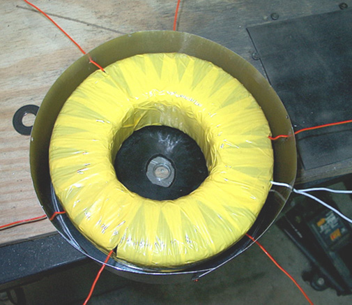 Supplying the Water The potassium hydroxide is not used up when the electrolyser is operated. A small amount leaves the electrolyser in the form of vapour but this is washed out of the gas in the first bubbler. Two bubblers are used, the first is located beside the electrolyser and connected to it via a one-way valve. The second bubbler is located close to the engine. From time to time, the water in the bubblers is poured back into the electrolyser and that prevents the loss of any potassium hydroxide. Not only does this conserve the potassium hydroxide, but it also protects the engine as potassium hydroxide has a very bad effect inside the engine itself. The overall water system is like this in broad outline, omitting the electrical safety devices:  A probe inside the electrolyser senses when the average level of the electrolyte has dropped and powers up the water pump to inject more water into the electrolyser. The rate of gas production is so high with the pulsed system that the electrolyte level is place at about half the plate height. That is some three inches below the tops of the plates. Because of this violent action, the water-level sensor needs to be operated from the electrolyte outside the plates where the surface of the electrolyte does not move so violently. A serious issue with an electrolyser of this type is dealing with water loss. As the plates have to be spaced closely together and the since the electrolyte between the cells is effectively isolated from the electrolyte in the other cells, driving a mile down the road is liable to lower the water level by half an inch (say, one centimetre). It is essential to keep replacing the water which is used. Two things have to be dealt with: 1. Sensing when the electrolyte level has fallen, and 2. Creating some device for getting extra water into each cell Simple electronics provides the answer to sensing the level of the electrolyte, and a windscreen-washer water pump can be used to inject the additional water. A sensor for the water in the cells can be on just one cell. If the water level of any one cell falls below the level in the other cells, then the gas produced in that cell will be slightly less than the other cells, so it will lose less water until the water levels match again. Also, Bob recommends cutting the slots which hold the plates, 3 thousandths of an inch (0.003 inch or 0.075 mm) larger than the actual thickness of the metal plates. This effectively blocks electrical leakage between adjacent cells but does allow a very gradual migration of water between the cells to help maintain an even water surface across the cell. The water-level sensor can be just one stiff stainless steel wire run down each side of any cell. These wires should be insulated to make sure that They do not short-circuit to either (or both) of the plates on each side of them. They should be set so that their tips are at the intended surface level of the electrolyte. If the electrolyte level drops below the tip of the wire sensors, then the resistance between the wires will fall, indicating that more water is needed. This can switch the water pump on, which will raise the water level until the electrolyte level reaches the tip of the wire again. A possible circuit for doing this is shown here:  When the level of the electrolyte falls, the sensor wires come clear of the liquid and the voltage at point ‘A’ rises. Provided that this situation remains for a second or two, capacitor C2 charges up and the voltage on the base of transistor Tr1 rises, causing it to switch on. Transistors Tr1 and Tr2 are wired as a Schmitt trigger, so transistor Tr2 changes state rapidly, raising the voltage at its collector, and causing transistor Tr3 to power the relay on. The relay contacts switch the water pump on, which raises the level of the electrolyte until it reaches the sensor wires again. This flips the circuit back into its standby state, powering down the water pump. Resistor R1 feeds capacitor C1 to reduce the effects of variations of voltage reaching the sensor circuit. The components shown here are not critical and there must be at least twenty alternative designs for this circuit. A possible physical layout for this circuit is shown here: The build is based on using the standard 10-strip, 39-hole strip-board. For convenience in drawing, the holes are represented as the points where the lines cross in the diagram shown here:  The horizontal lines represent the copper strips and the intersections with the vertical lines represents the matrix of holes. Many different layouts could be used for this circuit, so the following diagram is only a suggestion:   Components: R1 100 ohms C1 1000 microfarad 35 volt or higher R2 1,000 ohms C2 330 microfarad 16 volt or higher R3 10,000 ohms R4 1,800 ohms D1 1N4001 or similar 100 volt or higher 1 amp R5 18,000 ohms R6 18,000 ohms Tr1 to Tr3 2N2222 or 2N2222A or similar R7 3,900 ohms 40V, 800 mA, 500 mW, gain 100 - 300   To combat splashing of the electrolyte, a layer of aquarium matting is placed over the tops of the plates. In the diagram above, only a few of the 101 plates are shown, in order to keep the drawing narrow enough to fit on the page. The plates at each end have a stainless steel strap welded to them in order to allow for simple and robust electrical connections to be made through the case. The water supply is arranged to feed equal amounts of water to each cell. The design for this supply pipe has recently been improved by Ed Holdgate and Tom Thayer and Ed now supplies one along with the precision housings which he makes for Bob’s design. The new design has a water-supply pipe with very accurately cut slots in it. The lengths of the slots are directly related to how far along the pipe they are positioned. The objective is to have the same amount of water coming out of each slot even though the water pressure drops the further along the pipe the slot is located. That water supply pipe is then housed in an outer pipe which has a hole drilled in it exactly above each of the bodies of electrolyte trapped between the plates (a 3/16” spacing):  This water supply pipe arrangement works well in practice and it looks surprisingly like the gas take-off pipe which has a series of holes drilled along the top of it:  This arrangement works well as it allows large volume gas flow out of the cell and yet makes it difficult for any splashes of electrolyte to make it into the pipe. Connecting to the Engine: The Bob Boyce HHO gas system produces such a very high gas output that one inch (25 mm) pipes are needed to carry the gas from the electrolyser to the engine. Because of the speed of the pressure wave caused if HHO gas ignites, no pop-off or shatter-disc system has sufficient time to operate. In addition, Bob’s system produces the top grade of HHO gas and as that has the highest energy level possible, it explodes spontaneously at a pressure of just 15 psi. To deal with this situation, and the very high rate of gas flow which has to be handled, two very robust bubblers and one particle filter need to be used on the output of the electrolyser as shown here:  For those people living in America, Bob recommends the use of this bubbler: 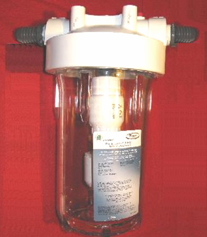 This is a bubbler constructed from "Whole Household Prefiltration" units supplied by Home Depot, which unfortunately, may cost more than US $100 each. 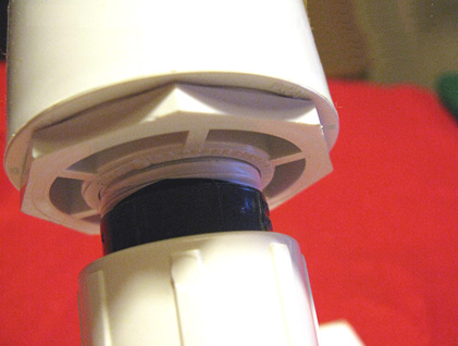 These units come with a domed cap which needs to be drilled out with a large number of 1/16” holes like this:  An important point with this unit is that the flow through the bubbler is in the opposite direction to the arrows moulded on the outside of the unit: 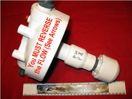 Also, the pressure at which it operates needs to be dropped from normal household water pressure to the 0.5 psi. gas pressure needed for use as a bubbler. This is achieved by replacing the ball valve inside the unit with a much weaker version available from the KBI company, reference code KC1000 and costing about US $10. If you get one, be sure to specify a 0.5 psi pressure version as they have more than one type. It is important that the end cap be a domed variety as shown above. This is necessary as it prevents bubbles joining together before streaming upwards through the water. The particle filter housing is a French-made unit sold by Home Depot under the name of "SmartWater" and reference number GXWH04F and it costs under US $20. As the filter supplied with the unit is not fine enough, so a 1-micron filter needs to be bought from Ace Hardware to replace the standard 4-micron filter supplied with the filter housing. This 1-micron adapted filter also acts as a back-flash preventer: 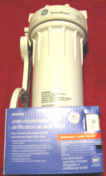 Practical Issues No matter which variety of electrolyser cell is used, it is essential to put a bubbler between it and the engine intake. This is to prevent any accidental ignition of the gas reaching the electrolysis cell. Also, no electrolyser should be operated or tested indoors. This is because the gas is lighter than air so any leak of gas will cause the gas to collect on the ceiling where it can cause a major explosion when triggered by the slightest spark (such as is generated when a light switch is turned on or off). Hydrogen gas escapes very easily indeed as its atoms are very, very small and can get through any tiny crack and even directly through many apparently solid materials. Testing electrolysers should be done outdoors or at the very least, in very well-ventilated locations. Using at least one bubbler is an absolutely vital safety measure. A typical bubbler looks like this: Bubbler construction is very simple indeed. It can be any size or shape provided that the outlet of the entry tube has at least five inches (125 mm) of water above it. Plastic is a common choice for the material and fittings are easy to find. It is very important that good sealed joints are made where all pipes and wires enter any container which has HHO gas in it. This, of course, includes the bubbler. Bob Boyce’s 101-plate units produce up to 100 lpm of gas, so these need large diameter gas piping to carry that substantial volume and the bubblers need to be big as well. It is also a good idea to drill additional holes in the entry pipe from half way down below the surface of the water, in order to create a larger number of smaller bubbles The anti-slosh filling or a baffle plate in the cap is to prevent the water in the bubbler from splashing up into the exit pipe and being drawn into the engine. Various materials have been used for the filling including stainless steel wool and plastic pot scourers. The material needs to prevent, or at least minimise, any water passing through it, while at the same time allowing the gas to flow freely through it. Let me stress again, that this document does NOT recommend that you actually build any of the items of equipment discussed here. The ‘HHO’ gas produced by electrolysis of water is extremely dangerous, explodes instantly and cannot be stored safely, so this document is strictly for information purposes only. However, to understand the process more fully, the following details would need to be considered carefully if somebody decided to actually build one of these high-voltage series-cell devices. There is a considerable difference between a mixture of hydrogen and oxygen gases (‘HHO’) and petroleum (gasoline) vapour. While they both can serve as fuel for an internal combustion engine, they have considerable differences. One major difference is that HHO gas burns very much faster than petrol vapour. That would not be a problem if the engine was originally designed to burn HHO gas. However, most existing engines are arranged to operate on fossil fuels. If using HHO gas to improve the burn quality and improve the mpg of a vehicle, no timing adjustments are normally necessary. However, all recent cars in the USA are fitted with an Electronic Mixture Controller and if nothing is done about that, a decrease in mpg may actually occur as the Controller may start pumping more fuel into the engine when it sees a change in the quality of the exhaust. Good information on how to deal with this problem can be found at the web site better-mileage.com which includes details of how to deal with the Controller. If an engine is run without any fossil fuel at all, then timing adjustments need to be made. Hydrocarbon fuels have large molecules which do not burn fast enough to be efficient inside the cylinder of an engine. What happens is that for the first fraction of a second after the spark plug fires, the molecules inside the cylinder split up into much smaller particles, and then these smaller particles burn so fast that it can be described as an explosion:  Because of the delay needed for the conversion of the hydrocarbon molecules to smaller particles, the spark is arranged to occur before the Top Dead Centre point. While the molecules are splitting up, the piston passes its highest point and the crankshaft is some degrees past Top Dead Centre before the driving pressure is placed on the head of the piston. This driving force then reinforces the clockwise rotation of the crankshaft shown in the diagram above and the motor runs smoothly. That will not happen if a HHO gas/air mix is substituted for the petrol vapour. HHO gas has very small molecule sizes which do not need any kind of breaking down and which burn instantly with explosive force. The result is as shown here:  Here, the explosion is almost instantaneous and the explosion attempts to force the piston downwards. Unfortunately, the crankshaft is trying to drive the piston upwards past the Top Dead Centre (‘TDC’) point, so the explosion will not help the engine run. Instead, the explosion will stop the crankshaft rotating, overload the crankshaft and connecting rod and produce excessive pressure on the wall of the cylinder. We do not want that to happen. The solution is to delay the spark until the piston has reached the position in its rotation where we want the explosion to take place - that is, in exactly the same place as it did when using petrol as a fuel. In the example above, the spark would be retarded (delayed) from 8 degrees before TDC to 10 degrees after TDC, or 18 degrees overall. The spark is ‘retarded’ because it needs to occur later in the rotation of the crankshaft. The amount of retardation may vary from engine to engine, but with HHO gas, the spark must never occur before TDC and it is preferable that the crankshaft has rotated some degrees past TDC so that most of the push from the piston goes to turn the crankshaft and as little as possible in compressing the crankshaft. Diesel Engines Diesel engines do not have spark plugs and so there is no timing alterations needed with them. Any booster volume of HHO gas up to 80% of the cylinder contents can be added into the air entering a diesel engine and it automatically helps the mpg performance. If a really large volume of HHO gas is available, then the diesel engine is set to tick over on diesel and HHO gas is then added to rev the engine up and provide the power. The amount of HHO gas should not exceed four times the amount of diesel as engine overheating will occur if it does. Roy MacAlister has been running internal combustion engines on hydrogen and many mixtures of hydrogen and other fuels for forty years now. He advises anybody interested in implementing a system like this, to start with a single-cylinder engine of five horsepower or less. That way, the techniques are easily learnt and experience is gained in tuning a simple engine running on the new fuel. So, let us assume that we are going to convert a small generator engine. How do we go about it? First, we obtain our supply of the new fuel. In this case, let us assume that we will produce HHO gas using a multi-cell high-voltage series electrolyser as described earlier. This unit has an electrical cut-off operated by a pressure switch which operates at say, five pounds per square inch. Assuming that the electrolyser is capable of producing a sufficient volume of gas, this is roughly equivalent to a hydrogen bottle with its pressure regulators. In broad outline, the gas supply would look like this:  The physical connection to the engine is via a 6 mm (1/4 inch) stainless steel pipe, fitted with a standard knob-operated needle valve. The carburettor is removed altogether to allow maximum airflow into the engine, (or failing this, the throttle valve of the carburettor is opened wide and secured in that position). The stainless steel gas pipe has its diameter reduced further by the use of a nozzle with an internal diameter of 1 mm or so (1/16 inch or less), about the size of a hypodermic needle used by a vet. HHO gas has very small molecules and will flow very freely through tiny openings. The nozzle tip is pushed close to the intake valve and the gas feed pipe is secured in place to ensure no movement: 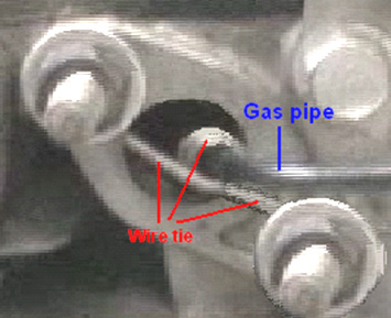 When the engine is about to be started, the needle valve can be hand-adjusted to give a suitable level of gas flow to maintain tick-over, but before that can happen, the timing of the spark needs to be adjusted There are two main ways to adjust the timing. The first is mechanical, where an adjustment is made to the mechanism which triggers the spark. Some small engines may well not have a convenient way to adjust the timing by as much as is needed for this application. The second way is to delay the spark by an adjustable electronic circuit (for instance, an NE555 monostable driving a FET). This can either be built or bought ready made. One supplier which offers a dashboard-mounted manually controlled ready-built ignition delay unit is www.msdignition.com and there are others. Waste spark. As already discussed in chapter 10, there is one other very important consideration with small engines and that is the way in which the spark is generated. With a four-stroke engine, the crankshaft rotates twice for every power stroke. The spark plug only needs to fire every second time the piston approaches its highest position in the cylinder. This is not particularly convenient for engine manufacturers, so some simplify matters by generating a spark on every revolution. The extra spark is not needed, contributes nothing to the operation of the engine and so is called the “waste spark”. The waste spark does not matter for an engine running on fossil fuel vapour, but it does matter very much if the fuel is switched to HHO gas. As has been shown in the earlier diagrams, it is necessary to retard (delay) the spark by some eighteen degrees or so when using HHO gas, due to its very much faster ignition rate. Delaying the HHO fuel ignition point until after Top Dead Centre sorts out the situation in an entirely satisfactory manner for the Power Stroke of the engine. However, if the engine generates a spurious ‘waste spark’ that waste spark does cause a serious problem. In the case of the fossil fuel, any waste spark will occur towards the end of the Exhaust Stroke and it will have no real effect (apart from wasting electrical power). In the case of the HHO fuel, the engine has completed the Exhaust Stroke, the outlet valve has closed, the intake valve has opened and the gas is being drawn through the open inlet valve into the cylinder in the Intake Stroke. At that instant, there is an open passage from the spark plug, through the cylinder, through the open intake valve, to the gas supply pipe and through it to the bubbler between the electrolyser and the engine. If a waste spark takes place, it will ignite the gas:  The gas ignition is highly likely if there is a waste spark in an engine using HHO fuel and (the necessary) retarded ignition. Trying to eliminate the unwanted spark by using a ‘divide-by-two’ electronic counter circuit is not likely to be successful unless there is some mechanically certain way of triggering the counter circuit at start-up. The best way of overcoming a waste spark, if the engine has one, is to use a 2:1 gearing arrangement on the output shaft of the motor and using the slower shaft to trigger the spark. Multi-cylinder engines do not usually have a waste spark. It is also possible to operate a contact from either the camshaft or directly from one of the valve stems. It has also been suggested that using a pressure-operated switch on the exhaust system would be effective, and another suggestion is to delay the opening time of the intake valve until after waste spark has occurred, though this may create a good deal more engine noise. Once some experience has been gained in operating a single cylinder engine on HHO gas, the move to a full-sized engine is not very difficult. Each cylinder of the large engine is pretty much the same as the small engine. Instead of running a small tube down the carburettor intake of each cylinder, it is more convenient and economic to use the existing intake manifold, leave the throttle wide open and run the HHO gas pipe into the manifold. A flexible stainless steel pipe section should be used to absorb the vibration of the engine relative to the electrolyser. Roy McAlister suggests using a knob-operated needle valve to set the idling speed to about 1,000 rpm and placing a throttle-operated lever valve in parallel with it for applying more power to the engine: It is not immediately clear to me why this arrangement is recommended as the knob-operated needle valve use to set the idling rate appears to be redundant. There appears to be no particular reason why a screw adjustment could not be used on the lever valve linked to the accelerator pedal of the vehicle. If that were done, then the throttle screw could be used to set the idle rate and the screw locked in position. That way, the needle valve and two Y-connectors could be dispensed with. The only possible reason which suggests itself is that there is slightly less physical construction needed for the recommended way shown here:  One supplier of flexible tubing suitable for this sort of work is www.titeflexcommercial.com but there will be many others. Engine Size Limits A 101-plate Boyce electrolyser accurately built, properly cleansed and conditioned, produces about 50 litres per minute of HHO gas continuously, when tuned properly and can sustain short bursts of 100 lpm. It is really not possible to say how much HHO gas is needed to operate any particular engine as the energy requirement varies so much from engine to engine even though they may have the same engine capacity. However, is very rough ball-park figures, it would not be unusual for a 2 litre capacity engine to run satisfactorily on 100 lpm of HHO gas. Please remember that when flow rates like 100 lpm or more are being dealt with, that it is essential to use a large-diameter pipe (say, one-inch diameter) from the electrolyser onwards. Also, the bubblers need to be physically larger. It is essential to avoid any possibility of large HHO gas bubbles forming a continuous path through the water in the bubbler as that would allow a flame-front to pass directly through the water in the bubbler which is exactly what the bubbler is there to prevent, so don’t skimp on the size of the bubblers, especially as they will only be half-filled when the gas flow rate is very high. Bob Boyce explains the present limits on gas production as follows: The impedance of the “MicroMetals T650” toroidal core reaches a maximum at 36 square inches per plate, it is possible to use one long 201-plate electrolyser, powered with double the voltage. The problem is that we can’t increase the current density as it would increase the toroid temperature which would cause the permeability to decrease. However, we can increase the voltage without worrying about increasing the toroid temperature, so going to 240 volts AC is not a problem. A 201-plate electrolyser could achieve 200 lpm which would be able to power a 3 to 4 litre engine. Ideally, an electrolyser of that type would have a microprocessor controller circuit board, as that should generate faster pulse transition speeds than the present circuit board. An electrolyser of that type would need a revised case design to take stainless steel plates which are 9 inches wide and 6 inches tall. The electrolyte level would then be set to a 4 inch depth, giving the same 36 square inches of active plate area. A 101-plate electrolyser measures about 20 inches in length. A 201-plate unit would be about 40 inches long and so would fit into the boot (trunk) of a car or the back of a pick-up. This means that there is still more potential left in the “T650” toroid before there is any need to find a larger toroid. An 8 inch toroid with a 101-plate unit could fuel an engine of up to 4 litres capacity. A 10 inch toroid driving a 101-plate unit could fuel a 5 litre engine. In these cases, the plate areas would be larger than 6” x 6” because with a larger toroid, the current can be increased without overheating the toroid and lowering it’s permeability. The information from Micrometals is that their hydraulic press can make toroids up to 8 inches in diameter, but the success rate diminishes as the diameter increases. As it is, the success rate for making the 6.5 inch diameter is their best economical rate. For larger diameters, the cost of the increased failure rate is passed on to the buyers. There is word of a small private Canadian outfit that is working with 5 gallon pails of mining tailings to extract high-permeability materials which can be used to make larger toroids. They crush the tailings into fine powder with a huge milling stone, then pass the powder under a magnet to collect the magnetic material. They do this several times and then mix the remaining material with a binder to form a toroid. Every company in the toroid making industry has their own proprietary formula for making toroids. This particular Canadian company's 6.5 inch toroid matches the Micrometals T650 pretty well. If there is enough interest, they can quote a quantity rate for a larger toroid. Stationary Applications Some people wish to try home applications with an electrolyser of this type, and they ask about powering the unit directly from the mains, rather than from the electrical system of a vehicle. This is a practical proposition and it has the advantage that size and weight are no longer of any great importance. The circuit would alter very slightly for this application as shown here:  Here, instead of an inverter to create 110 volts AC, a car battery charger or mains Power Supply Unit is needed to provide the same voltage that the vehicle electrics would have provided. It would probably be worth putting a large value capacitor across the output of the car battery charger to help smooth out the voltage ripple which it will produce. Don’t forget that it needs to be able to supply considerable current and so it will be rated as a “heavy-duty” battery charger. If a 200-cell unit is to be used, then a 1:2 mains step-up transformer will also be needed to raise the mains voltage to 220 volts. In countries which have a 220 volt mains supply, then a 2:1 step-down mains transformer would be needed for a 100-cell unit but not for a 200-cell unit. The circuit would then be:  Bob Boyce’s Experiences: Bob had an electronics business down in south Florida where he owned and sponsored a small boat-race team through his business, starting in 1988. He had a machine shop behind his business, where he did engine work. He worked on engines for other racers and a local minisub research outfit which was building surface-running drone type boats for the DEA. He delved into hydrogen research and started building small electrolysers using distilled water mixed with an electrolyte. He then resonated the plates to improve the efficiency of the units. He discovered that with the right frequencies, He was able to generate ‘monatomic’ Hydrogen and Oxygen rather than the more common ‘diatomic’ versions of these gasses. When the ‘monatomic’ gasses are burnt, they produce about four times the energy output produced by burning the more common diatomic version of these gasses. About 4% of diatomic Hydrogen in air is needed to produce the same power as petrol, while slightly less than 1% of monatomic Hydrogen in air is needed for the same power. The only drawback is that when stored at pressure, monatomic hydrogen reverts to its more common diatomic form. To avoid this, the gas must be produced on-demand and used right away. Bob used modified Liquid Petroleum carburettors on the boat engines to let them run directly on the gas produced by his electrolysers. Bob also converted an old Chrysler car with a slant six-cylinder engine to run on the hydrogen set-up and tested it in his workshop. He replaced the factory ignition with a high energy dual coil system and added an optical pickup to the crankshaft at the oil pump drive tang to allow external ignition timing adjustment. He used Bosch Platinum series spark plugs. Bob never published anything about what he was working on, and he always stated that his boats were running on hydrogen fuel, which was allowed. Many years later that he found that he had stumbled on was already discovered and known as "Browns Gas", and there were companies selling the equipment and plans to make it. Bob’s electrolyser is fairly simple to make but it requires a lot of plates made of 316 stainless steel able to withstand the more exotic electrolytes which are more efficient, a plastic box to contain the plates, 1/8" spacers to keep the rows of plates apart, the electrolyte, and an adjustable-frequency modified pseudo-sinewave inverter for the drive electronics. A total of 101 plates 6 inches square are used to give a large surface area. These have their surfaces scoured with coarse sandpaper in an "X" pattern to give a fine crosshatch grain which added fine sharp points to the surfaces. This is found to improve the efficiency of the electrolysis. The box has two threaded ports, a small one for injecting replacement distilled water, and a larger one for extracting the HHO gas. Under the top cover is a piece of plastic matting to prevent sloshing. It is very important to keep the electrolyte level below the tops of the plates to prevent current bypassing any cells and creating excessive water vapour. Bob places a 5 Pounds per Square Inch cut-off switch in a tee on the water injection port that shut the drive electronics down when the pressure in the unit hit 5 PSI. This allows the unit to be able to supply on demand without building up too much pressure in low-demand situations. He builds a bubbler from a large home cartridge type water-filter housing to prevent any backfire from travelling back up the gas feed pipe to the electrolyser. Without some sort of bubbler there is the risk of the electrolyser exploding if a flame front from the engine flows back to it. The copper mesh screens designed for welding gasses will not work as hydrogen has a much higher flame propagation speed which passes straight through the copper mesh. The bubbler should be placed close to the engine so as to limit the amount of recombination of the gasses from monatomic to diatomic varieties. The HHO gas should be fed to the vapour portion of a Liquid Petroleum Gas carburettor system. The carburettor will have to be modified for hydrogen use (different mixture rate than propane) and adjusted for best performance with the system running. Bob found that the best electrolytes to use were Sodium Hydroxide (NaOH) and Potassium Hydroxide (KOH). While Sodium Hydroxide works well and is much easier to get (‘Red Devil’ lye found in most department stores) than the slightly more efficient Potassium Hydroxide. Whatever is used, be very careful what construction materials are used. Make absolutely sure that they are compatible with the chosen electrolyte (Plexiglas acrylic sheet was what Bob used). Never use glass containers for mixing or storing Potassium Hydroxide. Bob never had the chance to drive the test Chrysler on the road with this system. Instead, he placed the rear end up on jack-stands and ran the engine under no-load conditions in drive just to test and tune the system and get an idea of how well the engine held up on the hydrogen fuel. The vehicle was run for a milometer recorded distance of one thousand miles in this set-up with the hydrolysis being fully powered by the alternator of the vehicle. With the vehicle running at idle, the drive electronics consumed approximately 4 to 4.3 Amps @ 13.8 V DC. With the rear wheels off of the ground, and the engine running with the vehicle speedometer registering 60 mph, the drive electronics drew approximately 10.9 to 11.6 Amps @ 13.8 V DC. The unit does not use "normal brute force" electrolysis when operating in high efficiency mode. It relies mainly on a chemical reaction that takes place between the electrolyte used and the metal plates, which is maintained by electrical energy applied and stimulated into higher efficiency by the application of multiple harmonic resonances which help to "tickle" the molecules apart. Multiple cells in series are used to lower the voltage per cell and limit the current flow in order to reduce the production of water vapour. It relies on the large surface area of the total number of cells to get the required volume of fuel vapour output. In the first prototype of this design, Bob used a custom built controller/driver which allowed a lot of adjustment so that performance could be tested using different frequencies, voltages, and waveforms individually. The result was a pattern of 3 interwoven square waves rich in harmonics that produced optimum efficiency. When Bob had the basics figured out he realised that he could just replace the custom controller/driver unit with a modified inverter (much easier than building a unit from scratch). He experimented using a 300 watt pseudo-sine wave inverter that had been modified so the base frequency could be adjusted between 700 and 800 Hz. The stepped sine wave output was fed through a bridge rectifier which turned each stepped sine wave into two positive stepped half waves. Each of these half waves had 8 steps, so a single cycle was turned into 16 steps. The resulting output, while not consisting of intermixed square waves, was still rich in harmonics, and it was much easier to adjust to the point of resonance than trying to tune 3 separate frequencies. Please note that these inverters are no longer available for purchase and that Bob’s triple oscillator board design is far superior, giving more than double the output produced by the old inverter and is definitely the board to use with Bob’s electrolyser. The frequency range can change depending on the number of steps in the pseudo-sine wave of the inverter you choose since not all inverters are created equal. The desired effect is caused by the multiple harmonic resonances in the inverter output at higher frequencies. You will know when you hit resonance by the dramatic increase in gas output. The frequency does vary a bit depending on what electrolyte is used, the concentration of the electrolyte solution, the temperature of the electrolyte, water purity, etc. Bear in mind that Bob’s electrolyser tank was large enough to hold 61 plates of 316 grade stainless steel which were 6" X 6" each, spaced 1/8" apart, to create 60 cells in series, with the 130 V DC power from the inverter, through the bridge rectifier, applied to the end plates only. That gave 4,320 square inches of surface area, plenty of surface area to produce enough fuel for a vehicle engine. The best electrolyte for efficiency was Potassium Hydroxide, and the electrolyte level must be kept below the tops of the plates to prevent any current from bypassing the plates and creating excess water vapour through heating. Distilled water was used to prevent contamination of the electrolyte which would result in reduced performance and efficiency. The unit had 316 grade stainless steel wires welded to the tops of the end plates. The other ends of the wires were welded to 316-grade stainless steel bolts which passed through holes in the ends of the container, with rubber o-ring gaskets inside and out, located above the liquid level. There was a PVC spray bar attached on the inside of the chamber to the water injection port with tiny holes drilled along its length on the underside to supply replacement water evenly to the cells when the water pump was switched on. A backflow-prevention valve on top of the tee was used to keep the gas from flowing back into the water lines. There was a mat of interwoven plastic fibres (air conditioner filter material) cut and fitted on top of the plates to help prevent sloshing. Do not use fibreglass mat, which could cause a severe reaction with some electrolytes, like Potassium Hydroxide. It is very important to understand that unless an engine is originally designed for, or later modified for, running on vapour fuel such as Liquid Petroleum Gas (natural gas), that water mist injection be added. Unless the engine has the proper valves for vapour fuel, the stock valves will not survive for extended run times on vapour fuel of any kind without additional cooling of some sort. This is an issue of valve design by the vehicle manufacturers, not something detrimental because of HHO gas combustion. The manufacturers want to prevent their cars from being adapted to high mileage operation without adverse effects, so they designed the valves to fail if not cooled by excess raw fossil fuel. Pulsed Water-splitters There is a much more efficient way of converting water into a hydroxy gas mix. Unlike the electrolysis devices already described, this method does not need an electrolyte. Pioneered by Stanley Meyer, pulse trains are used to stress water molecules until they break apart, forming the required gas mix. Henry Puharich also developed a very successful system with a somewhat different design. Neither of these gentlemen shared sufficient practical information for us to replicate their designs as a routine process, so we are in a position today where we are searching for the exact details of the methods which they used. The first significant replication of which I am aware, came from Dave Lawton of Wales. By using very considerable tenacity, he discovered the practical details of how to replicate one of Stan Meyer's early designs which is called by the rather confusing name of the "Water Fuel Cell". Dave's work was copied and experimented with by Ravi Raju of India who had considerable success and who posted videos of his results on the web. More recently, Dr Scott Cramton of the USA has adapted the design construction slightly and achieved very satisfactory rates of electrical efficiency, producing some 6 lpm of hydroxy gas for just 3 amps of current at 12 volts.  The video of Dave Lawton’s replication of Stanley Meyer’s demonstration electrolyser (not Stan's production system) seen here has caused several people to ask for more details. The electrolysis shown in that video was driven by an alternator, solely because Dave wanted to try each thing that Stan Meyer had done. Dave’s alternator and the motor used to drive it are shown here:  The technique of DC pulsing requires the use of electronics, so the following descriptions contain a considerable amount of circuitry. If you are not already familiar with such circuits, then you would be well advised to read through Chapter 12 which explains this type of circuitry from scratch. The field coil of Dave's alternator is switched on and off by a Field-Effect Transistor (a “FET”) which is pulsed by a dual 555 timer circuit. This produces a composite waveform which produces an impressive rate of electrolysis. The tubes in this replication are made of 316L grade stainless steel, five inches long although Stan’s tubes were about sixteen inches long. The outer tubes are 1 inch in diameter and the inner tubes 3/4 inch in diameter. As the wall thickness is 1/16 inch, the gap between them is between 1 mm and 2 mm. The inner pipes are held in place at each end by four rubber strips about one quarter of an inch long. The container is made from two standard 4 inch diameter plastic drain down-pipe coupler fittings connected to each end of a piece of acrylic tube with PVC solvent cement. The acrylic tube was supplied already cut to size by Wake Plastics, 59 Twickenham Road, Isleworth, Middlesex TW7 6AR Telephone 0208-560-0928. The seamless stainless steel tubing was supplied by www.metalsontheweb.co.uk It is not necessary to use an alternator - Dave just did this as he was copying each thing that Stan Meyer did. The circuit without the alternator produces gas at about the same rate and obviously draws less current as there is no drive motor to be powered. A video of the non-alternator operation can be downloaded here. Dave's electrolyser has an acrylic tube section to allow the electrolysis to be watched, as shown here: 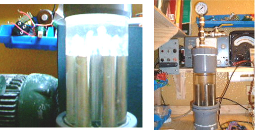 The electrolysis takes place between each of the inner and outer tubes. The picture above shows the bubbles just starting to leave the tubes after the power is switched on. The picture below shows the situation a few seconds later when the whole of the area above the tubes is so full of bubbles that it becomes completely opaque: 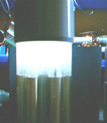 The mounting rings for the tubes can be made from any suitable plastic, such as that used for ordinary food-chopping boards, and are shaped like this: 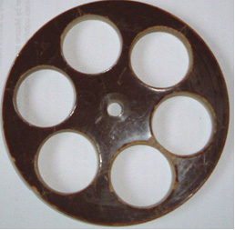 And the 316L grade stainless steel, seamless tubes are held like this: 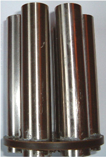 Here is the assembly ready to receive the inner tubes (wedged into place by small pieces of rubber): 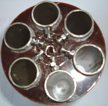 The electrical connections to the pipes are via stainless steel wire running between stainless steel bolts tapped into the pipes and stainless steel bolts running through the base of the unit:  The bolts tapped into the inner tubes should be on the inside. The bolts going through the base of the unit should be tapped in to give a tight fit and they should be sealed with Sikaflex 291 or marine GOOP bedding agent which should be allowed to cure completely before the unit is filled for use. An improvement in performance is produced if the non-active surfaces of the pipes are insulated with any suitable material. That is, the outsides of the outer tubes and the insides of the inner tubes, and if possible, the cut ends of the pipes. While Dave’s style of construction is simple and straightforward, recently, a copy of one of Stan Meyer’s actual construction drawings has surfaced. The image quality of this copy is so low that much of the text can’t be read, so the replication presented here may not be exact or might be missing some useful item of information. Stan’s construction is unusual. First, a piece of plastic is shaped as shown here:  The size of this disc is matched exactly to the piece of clear acrylic used for the body of the housing. The drawing does not make it clear how this disc is attached to the acrylic tube, whether it is a tight push fit, glued in place or held in position with bolts which are not shown. The implication is that a ring of six bolts are driven through the top and tapped into the acrylic tube, as these are shown on one of the plan views, though not on the cross-section. It would also be reasonable to assume that a similar ring of six bolts is also used to hold the base securely in position. There is a groove cut in the plastic base to take an O-ring seal which will be compressed tightly when the disc is in place. There are either two or three threaded stud recesses plus two through holes to carry the electric current connections. The pipe support arrangement is unusual:  A ring of nine evenly-spaced inner pipes are positioned around the edge of a steel disc which is slightly smaller than the inside dimension of the acrylic tube. The pipes appear to be a tight push-fit in holes drilled very accurately through the disc. These holes need to be exactly at right-angles to the face of the disc in order for the pipes to be exactly aligned with the acrylic tube – definitely a drill-press job. The disc is mounted on a central threaded rod which projects through the plastic base disc, and a plastic spacer is used to hold the disc clear of the studs positioned at ninety degrees apart around the outer edge of the base disc. The mounting for the outer tubes is also most unusual. A piece of steel plate is cut with nine projecting arms at evenly-spaced positions around a circular washer shape as shown here:  This piece has four holes drilled in it to match the stud positions of the plastic base piece. The number of studs is not specified and while I have shown four, the plate resonance might be helped if there were just three. The size is arranged so that when the arms are bent upwards at right-angles, they fit exactly against the inner face of the acrylic tube. These arms get two bends in them in order to kink them inwards to form mounts for the outer tubes. The degree of accuracy needed her is considerable as it appears that there are no spacers used between the inner and outer tubes. This means that the very small gap of 1.5 mm or so has to be maintained by the accuracy of these mounts for the outer tubes. It should be noted that the inner tubes are much longer than the outer tubes and that the outer tubes have a tuning slot cut in them. All of the inner tubes are mechanically connected together through their steel mounting disc and all of the outer tubes are connected together through the ring-shaped steel disc and its kinked arm mounts. It is intended that both of these assemblies should resonate at the same frequency, and they are tuned to do just that. Because the inner tubes have a smaller diameter, they will resonate at a higher frequency than a larger diameter pipe of the same length. For that reason, they are made longer to lower their natural resonant frequency. In addition to that, the slots cut in the outer tubes are a tuning method which raises their resonant pitch. These slots will be adjusted until every pipe resonates at the same frequency. Looking initially at the mechanical design, suggests that the assembly is impossible to assemble, and while that is almost true, as it will have to be constructed as it is assembled and it appears that the inner and outer pipe assembly can’t be taken apart after assembly. This is the way they are put together:  The ring support for the outer pipes is not bolted securely to the plastic base but instead it is spaced slightly above it and mounted on just the stud points. This ring is underneath the slightly smaller diameter disc which holds the inner pipes. This makes it impossible for the two components to be slid together or apart, due to the length of the pipes. This suggests that either the inner pipes are pushed into place after assembly (which is highly unlikely as they will have been assembled before for tuning) or that the outer pipes are welded to their supports during the assembly process (which is much more likely). One of the “studs” is carried right through the plastic base in order that it can become the positive connection of the electrical supply, fed to the outer pipes. The central threaded rod is also carried all the way through the plastic base and is used to support the steel plate holding the inner pipes as well as providing the negative electrical connection, often referred to as the electrical “ground”. Another plastic disc is machined to form a conical lid for the acrylic tube, having a groove to hold an O-ring seal and the water inlet for refilling and the gas output tube. The drawing mentions the fact that if tap water is used, then the impurities in it will collect in the bottom of the electrolyser when the water is removed by being converted to hydroxy gas. This means that the cell would have to be rinsed out from time to time. It also draws attention to the fact that the gasses dissolved in the tap water will also come out during use and will be mixed with the hydroxy gas output. When these various components are put together, the overall cell construction is shown like this:  This cross-sectional view may be slightly misleading as it suggests that each of the nine outer pipes has its own separate bracket and this is probably not the case as they are connected together electrically through the steel ring-shaped disc and should vibrate as a single unit. It is tempting to use separate brackets as that would allow the assembly to be taken apart quite easily, but the electrical contacts of such a system would be much inferior and so it is not to be recommended. Because of the way that all of the inner pipes are connected together and all of the outer pipes are connected together electrically, this form of construction is not suited to the three-phase alternator drive shown below, where the nine pipes would have to be connected in separate sets of three. Instead, the solid-state circuit is used, which is very effective and which does not have the size, weight, noise and increased current of the alternator arrangement. If accuracy of construction is a problem, then it might be possible to give the outer pipes a deliberate slope so that they press against the inner pipes at the top, and then use one short spacer to force them apart and give the desired spacing. It seems clear that Stan worked to such a degree of constructional accuracy that his pipes were perfectly aligned all along their lengths. Dave Lawton points out that the connection point of the brackets for the outer pipes is highly critical as they need to be at a resonating node of the pipes. The connection point is therefore at 22.4% of the length of the pipe from the bottom of the pipe. Presumably, if a slot is cut in the top of the pipe, then the resonant pipe length will be measured to the bottom of the slot and the connection point set at 22.4% of that length. Dave Lawton’s pipe arrangement can be driven either via an alternator or by an electronic circuit. A suitable circuit for the alternator arrangement is:  In this rather unusual circuit, the rotor winding of an alternator is pulsed via an oscillator circuit which has variable frequency and variable Mark/Space ratio and which can be gated on and off to produce the output waveform shown below the alternator in the circuit diagram. The oscillator circuit has a degree of supply de-coupling by the 100 ohm resistor feeding the 100 microfarad capacitor. This is to reduce voltage ripple coming along the +12 volt supply line, caused by the current pulses through the rotor winding. The output arrangement feeding the pipe electrodes of the electrolyser is copied directly from Stan Meyer’s circuit diagram. It is not recommended that you use an alternator should you decide to build a copy of your own. But if you decide to use one and the alternator does not have the windings taken to the outside of the casing, it is necessary to open the alternator, remove the internal regulator and diodes and pull out three leads from the ends of the stator windings. If you have an alternator which has the windings already accessible from the outside, then the stator winding connections are likely to be as shown here:  The motor driving Dave’s alternator draws about two amps of current which roughly doubles the power input to the circuit. There is no need for the size, weight, noise, mechanical wear and current draw of using a motor and alternator as pretty much the same performance can be produced by the solid-state circuit with no moving parts. Both circuits have been assessed as operating at anything from 300% to 900% of Faraday’s “maximum electrical efficiency”, it should be stressed that the inductors used in this circuit, form a very important role in altering and amplifying the voltage waveform applied to the cell. Dave uses two “bi-filar wound” inductors, each wound with 100 turns of 22 SWG (21 AWG) enamelled copper wire on a 9 mm (3/8”) diameter ferrite rod. The length of the ferrite rod is not at all critical, and a ferrite toroid could be used as an alternative, though that is more difficult to wind. These bi-filar coils are wound at the same time using two lengths of wire side by side. The solid-state circuit is shown here:  Circuit operation: The main part of the circuit is made up of two standard 555 chip timers. These are wired to give an output waveform which switches very rapidly between a high voltage and a low voltage. The ideal waveform shape coming from this circuit is described as a “square wave” output. In this particular version of the circuit, the rate at which the circuit flips between high and low voltage (called the “frequency”) can be adjusted by the user turning a knob. Also, the length of the ON time to the OFF time (called the “Mark/Space Ratio”) is also adjustable. This is the section of the circuit which does this:  The 100 ohm resistor and the 100 microfarad capacitor are there to iron out any ripples in the voltage supply to the circuit, caused by fierce pulses in the power drive to the electrolysis cell. The capacitor acts as a reservoir of electricity and the resistor prevents that reservoir being suddenly drained if the power supply line is suddenly, and very briefly, pulled down to a low voltage. Between them, they keep the voltage at point “A” at a steady level, allowing the 555 chip to operate smoothly. The very small capacitor “B” is wired up physically very close to the chip. It is there to short-circuit any stray, very short, very sharp voltage pulses picked up by the wiring to the chip. It is there to help the chip to operate exactly as it is designed to do, and is not really a functional part of the circuit. So, for understanding how the circuit works, we can ignore them and see the circuit like this:  This circuit generates output pulses of the type shown in green with the voltage going high, (the “Mark”) and low (the “Space”). The 47K variable resistor (which some people insist on calling a “pot”) allows the length of the Mark and the Space to be adjusted from the 50 - 50 shown, to say, 90 - 10 or any ratio through to 10 - 90. It should be mentioned that the “47K” is not at all critical and these are quite likely to be sold as “50K” devices. Most low cost components have a plus or minus 10% rating which means that a 50K resistor will be anything from 45K to 55K in actual value. The two “1N4148” diodes are there to make sure that when the Mark/Space 47K variable resistor is adjusted, that it does not alter the frequency of the output waveform in any way. The remaining two components: the 10K variable resistor and the 47 microfarad capacitor, both marked in blue, control the number of pulses produced per second. The larger the capacitor, the fewer the pulses per second. The lower the value of the variable resistor, the larger the number of pulses per second. The circuit can have additional frequency tuning ranges, if the capacitor value is altered by switching in a different capacitor. So the circuit can be made more versatile by the addition of one switch and, say, two alternative capacitors, as shown here:  The capacitors shown here are unusually large because this particular circuit is intended to run relatively slowly. In the almost identical section of the circuit which follows this one, the capacitors are very much smaller which causes the switching rate to be very much higher. Experience has shown that a few people have had overheating in this circuit when it is switched out of action, so the On/Off switch has been expanded to be a two-pole changeover switch and the second pole used to switch out the timing elements of the 555 chip. The complete version of this section of the circuit is then:  which just has one additional switch to allow the output to be stopped and the 12-volt supply line to be fed instead. The reason for this is that this part of the circuit is used to switch On and Off an identical circuit. This is called “gating” and is explained in Chapter 12 which is an electronics tutorial. The second part of the circuit is intended to run at much higher speeds, so it uses much smaller capacitors:  So, putting them together, and allowing the first circuit to switch the second one On and Off, we get:  The final section of the circuit is the power drive for the electrolyser cell. This is a very simple circuit. Firstly, the output of the second 555 chip is lowered by a basic voltage-divider pair of resistors, and fed to the Gate of the output transistor:  Here, the 555 chip output voltage is lowered by 220 / 820 or about 27%. When the voltage rises, it causes the BUZ350 transistor to switch on, short-circuiting between its Drain and Source connections and applying the whole of the 12-volt supply voltage across the load, which in our application, is the electrolyser cell:  The transistor drives the electrolysis electrodes as shown above, applying very sharp, very short pulses to them. What is very important are the wire coils which are placed on each side of the electrode set. These coils are linked magnetically because they are wound together on a high-frequency ferrite rod core and although a coil is such a simple thing, these coils have a profound effect on how the circuit operates. Firstly, they convert the 555 chip pulse into a very sharp, very short, high-voltage pulse which can be as high as 1,200 volts. This pulse affects the local environment, causing extra energy to flow into the circuit. The coils now perform a second role by blocking that additional energy from short-circuiting through the battery, and causing it to flow through the electrolysis cell, splitting the water into a mix of hydrogen and oxygen, both gases being high-energy, highly charged atomic versions of those gases. This gives the mix some 400% the power of hydrogen being burned in air. When the transistor switches off, the coils try to pull the transistor Drain connection up to a voltage well above the +12-volt battery line. To prevent this, a 1N4007 diode is connected across the cell and its coils. The diode is connected so that no current flows through it until the transistor Drain gets dragged above the +12-volt line, but when that happens, the diode effectively gets turned over and as soon as 0.7 volts is placed across it, it starts to conduct heavily and collapses the positive-going voltage swing, protecting the transistor. You can easily tell that it is the environmental “cold” electricity which is doing the electrolysis as the cell stays cold even though it is putting out large volumes of gas. If the electrolysis were being done by conventional electricity, the cell temperature would rise during the electrolysis. A John Bedini pulser circuit can be used very effectively with a cell of this type and it adjusts automatically to the resonant frequency as the cell is part of the frequency-determining circuit. The BUZ350 MOSFET has a current rating of 22 amps so it will run cool in this application. However, it is worth mounting it on an aluminium plate which will act as both the mounting and a heat sink but it should be realised that this circuit is a bench-testing circuit with a maximum current output of about 2 amps and it is not a Pulse-Width Modulation circuit for a high-current DC electrolyser. The current draw in this arrangement is particularly interesting. With just one tube in place, the current draw is about one amp. When a second tube is added, the current increases by less than half an amp. When the third is added, the total current is under two amps. The fourth and fifth tubes add about 100 milliamps each and the sixth tube causes almost no increase in current at all. This suggests that the efficiency could be raised further by adding a large number of additional tubes, but this is actually not the case as the cell arrangement is important. Stan Meyer ran his VolksWagen car for four years on the output from four of these cells with 16-inch (400 mm) electrodes, and Stan would have made a single larger cell had that been feasible. Although the current is not particularly high, a five or six amp circuit-breaker, or fuse, should be placed between the power supply and the circuit, to protect against accidental short-circuits. If a unit like this is to be mounted in a vehicle, then it is essential that the power supply is arranged so that the electrolyser is disconnected if the engine is switched off. Passing the electrical power through a relay which is powered via the ignition switch is a good solution for this. It is also vital that at least one bubbler is placed between the electrolyser and the engine, to give some protection if the gas should get ignited by an engine malfunction.  Although printed circuit boards have now been produced for this circuit and ready-made units are available commercially, you can build your own using stripboard if you want to. A possible one-off prototype style component layout for is shown here:  The underside of the strip-board (when turned over horizontally) is shown here:    Although using a ferrite ring is probably the best possible option, the bi-filar coil can be wound on any straight ferrite rod of any diameter and length. You just tape the ends of two strands of wire to one end of the rod and then rotate the rod in your hands, guiding the strands into a neat side-by-side cylindrical winding as shown here:   Dave, who built this replication, suggests various improvements. Firstly, Stan Meyer used a larger number of tubes of greater length. Both of those two factors should increase the gas production considerably. Secondly, careful examination of video of Stan’s demonstrations shows that the outer tubes which he used had a rectangular slot cut in the top of each tube:  Some organ pipes are fine-tuned by cutting slots like this in the top of the pipe, to raise it’s pitch, which is it’s frequency of vibration. As they have a smaller diameter, the inner pipes in the Meyer cell will resonate at a higher frequency than the outer pipes. It therefore seems probable that the slots cut by Stan are to raise the resonant frequency of the larger pipes, to match the resonant frequency of the inner pipes. If you want to do that, hanging the inner tube up on a piece of thread and tapping it, will produce a sound at the resonant pitch of the pipe. Cutting a slot in one outer pipe, suspending it on a piece of thread and tapping it, will allow the pitch of the two pipes to be compared. When one outer pipe has been matched to your satisfaction, then a slot of exactly the same dimensions will bring the other outer pipes to the same resonant pitch. It has not been proved, but it has been suggested that only the part of the outer pipe which is below the slot, actually contributes to the resonant frequency of the pipe. That is the part marked as “H” in the diagram above. It is also suggested that the pipes will resonate at the same frequency if the area of the inside face of the outer pipe (“H” x the inner circumference) exactly matches the area of the outer surface of the inner pipe. It should be remembered that as all of the pipe pairs will be resonated with a single signal, that each pipe pair needs to resonate at the same frequency as all the other pipe pairs. It is said that Stan ran his VolksWagen car for four years, using just the gas from four of these units which had pipe pairs 16-inchs long. A very important part of the cell build is the conditioning of the electrode tubes, using tap water. Ravi in India suggests that this is done as follows: 1. Do not use any resistance on the negative side of the power supply when conditioning the pipes. 2. Start at 0.5 Amps on the signal generator and after 25 minutes, switch off for 30 minutes 3. Then apply 1.0 Amps for 20 minutes and then stop for 30 minutes. 4. Then apply 1.5 Amps for 15 minutes and then stop for 20 minutes. 5. Then apply 2.0 Amps for 10 minutes and afterwards stop for 20 minutes. 6. Go to 2.5 Amps for 5 minutes and stop for 15 minutes. 7. Go to 3.0 Amps for 120 to 150 seconds. You need to check if the cell is getting hot...if it is you need to reduce the time. After the seven steps above, let the cell stand for at least an hour before you start all over again. You will see hardly any gas generation in the early stages of this conditioning process, but a lot of brown muck will be generated. Initially, change the water after every cycle, but do not touch the tubes with bare hands. If the ends of the tubes need to have muck cleaned off them, then use a brush but do not touch the electrodes!! If the brown muck is left in the water during the next cycle, it causes the water to heat up and you need to avoid this. Over a period of time, there is a reduction in the amount of the brown stuff produced and at some point, the pipes won’t make any brown stuff at all. You will be getting very good gas generation by now. A whitish powdery coat of chromium oxide dielectric will have developed on the surfaces of the electrodes. Never touch the pipes with bare hands once this helpful coating has developed. Important: Do the conditioning in a well-ventilated area, or alternatively, close the top of the cell and vent the gas out into the open. During this process, the cell is left on for quite some time, so even a very low rate of gas production can accumulate a serious amount of gas which would be a hazard if left to collect indoors. It has been suggested that if a BUZ350 can’t be obtained, then it would be advisable to protect the output FET against damage caused by accidental short-circuiting of wires, etc., by connecting what is effectively a 150-volt, 10 watt zener diode across it as shown here:  While this is not necessary for the correct operation of the circuit, it is helpful in cases where accidents occur during repeated testing and modification of the cell components.  Dr Scott Cramton. Dr. Cramton and his team of Laesa Research and Development scientists have been investigating and advancing this technology and they have reached an output of six litres per minute for an electrical input of 12 watts (1 amp at 12 volts). In addition, Dr. Cramton’s cell has stable frequency operation and is being run on local well water. The objective is to reduce the amount of diesel fuel needed to run a large capacity standard electrical generator. The style of design is similar to Stan Meyer’s original physical construction although the dimensions are slightly different. The cell body is transparent acrylic tube with end caps top and bottom. Inside the tube are nine pairs of pipes, electrically connected as three sets of three interspersed pipe pairs. These are driven by a three-phase pulsed supply based on a replication of Stan Meyer’s original cell. It consists of a Delco Remy alternator driven by a 1.5 horsepower 220 volt AC motor. This arrangement is, as was Stan Meyer’s, for demonstration purposes. In a working application, the alternator is driven by the engine being supplied with the hydroxy gas. The 120 degree phase separation is the critical component for maintaining the resonant frequency. It should be noted that the alternator must maintain a rate of 3,600 rpm while under load. It needs to be stressed that Dr. Cramton’s cell is very close in construction principles to Dave Lawton’s cell and the quality of construction is very important indeed. The first and foremost point which can be easily missed is the absolutely essential tuning of all of the pipes to a single, common frequency. This is the equivalent of tuning a musical instrument and without that tuning, the essential resonant operation of the cell will not be achieved and the cell performance will not be anything like the results which Dr. Cramton and his team are getting. Dr. Cramton is using 316L-grade stainless steel pipes 18 inches (450 mm) long. The outer pipes are 0.75 inches in diameter and the inner pipes 0.5 inches in diameter. This gives an inter-pipe gap of 1.2 mm. The first step is to get the pipes resonating together. First, the frequency of an inner pipe is measured. For this, a free internet frequency-analyzer program was downloaded and used with the audio card of a PC to give a measured display of the resonant frequency of each pipe. The download location is here The method for doing this is very important and considerable care is needed for this. The quarter-inch stainless steel bolt is pressed into the inner pipe where it forms a tight push-fit. It is very important that the head of each nut is pressed in for exactly the same distance as this alters the resonant frequency of the inner pipe. The steel connecting strip is then bent into its Z shape and securely clamped to the bolt with a stainless steel nut. The assembly of pipe, steel strip, nut and bolt is then hung up on a thread and tapped gently with a piece of wood and its resonant frequency measured with the frequency analyzer program. The frequency is fed into the program using a microphone. All of the inner pipes are tuned to exactly the same frequency by a very slight alteration of the insertion length of the bolt head for any pipe with a resonant frequency which is slightly off the frequency of the other pipes in the set of nine inner pipes. Next, the outer tubes are slotted to raise their resonant frequency to match that of the inner pipes. Their frequency is also measured by hanging them up and tapping them gently with a piece of wood. If the frequency needs additional raising, then the tube length is reduced by a quarter of an inch (6 mm) and the testing continued as before. Adjusting the width and length of the slot is the best method for adjusting the resonant frequency of the tube. A small file can be used to increase the slot dimensions. This procedure is time consuming and tedious but it is well worth the effort. The average finished length of the outer pipes is 17.5 inches (445 mm) and the slot dimensions 0.75 inch long and 0.5 inch wide (19 mm x 13 mm). When setting the resonant frequency of the outer pipes, it is important to have the clips in place. These "hosepipe", "jubilee" or "Terry" clips are used to make electrical connections to the outer pipes as shown in the diagrams and they do have an effect on the resonance of the pipes, so fit them before any tuning is done. The pipe arrangement is shown here:  The outer pipes are drilled and tapped to take either a 6/32” nylon bolt available from Ace hardware stores in the USA, or alternatively, drilled and tapped to take a 4 mm nylon bolt. Three of these bolt holes are evenly spaced around the circumference of each end of all of the outer pipes.  These nylon bolts are used to adjust and hold the inner pipe gently in the exact centre of the outer pipe. It is very important that these bolts are not over tightened as that would hinder the vibrations of the inner pipe. The bolts are adjusted so that a feeler gauge shows that there is exactly the same 1.2 mm gap all round, both top and bottom. The weight of the inner pipe is carried by a 3/4 inch (18 mm) wide strip of stainless steel bent into a Z-shape, and none of the weight is carried by the nylon bolts. Dr Cramton describes this Z-shaped steel strip as a “spring” and stresses its importance in constructing a set of resonating pipe pairs. The arrangement is shown here:  The supporting springy strip of steel is shown in blue in the above diagram as it also forms the electrical connection for the inner tubes. The outer tubes are held securely in position by two plastic discs which form a tight push-fit inside the 6” (150 mm) diameter acrylic tube which forms the body of the cell. The cell is sealed off with plastic caps (ideally, the upper one being screw threaded for easy maintenance) and the electrical connections are carried through the lower cap using 1/4” (6 mm) x 20 stainless steel bolts. The bolts are sealed using washers and rubber O-rings on both sides of the cap. For clarity, the diagram above shows only the electrical connections for the inner pipes. The electrical connections for the outer pipes are shown in the following diagram. The connections are made at both the top and the bottom of each outer pipe by attaching a stainless steel hose clamp with a stainless steel bolt welded to each clamp. The wiring is then carried across inside the cell so that all six connection points for each set of three pipes are carried out through the base of the cell with just one bolt, again, sealed with washers and rubber O-rings. The nine pipe pairs are electrically connected in three sets of three, and each set is fed with a separate phase of a 3-phase waveform. This sets up an interaction through the water and produces a complex pulsing waveform with each set of pipes interacting with the other two sets. The sets are arranged so that the individual pipes of each set are interspersed with the pipes of the other two sets, making the sets overlap each other as shown in this diagram:  For clarity, the diagram above does not show the electrical connections for the inner pipes and it omits the pipes of the other two groups of three, the water-level sensor, the gas take off pipe and the gas-pressure sensor. At this time, Dr. Cramton is driving the pipe arrays with the circuit shown below. It uses an AC sinewave generated by a pulsed alternator. The current fed to the motor driving the alternator accounts for about 24 watts of power while the current drive to the alternator winding is just 12 watts. It should be realised that the alternator can easily drive many cells, probably without any increase in power required. Dr. Cramton is investigating methods of producing the same waveform without the need for an alternator and while that would be useful, it should be realised that a gas output of six litres per minute for a power input of only 36 watts is a very significant result. Others have shown that it is possible to power a 5.5 kilowatt electrical generator on hydroxy gas alone with a flow rate of this sort of magnitude, and obviously, the 36 watts can very easily be provided from that 5.5 kilowatt output. It is absolutely essential that the pipe pairs are “conditioned” as there will be very little gas production until the white conditioning layer is built up on the active surfaces of the pipes. As has already been described, one method is by powering the cell up for a few minutes, and then letting it rest unused for a time before repeating the process. Dr. Cramton emphasises that at least a hundred hours of conditioning will be needed before the gas output volume starts to rise, and it will be three months before the white conditioning layer reaches its full thickness and the gas production rate increases dramatically. Dr Cramton stresses that it is the mechanical construction which will make the difference in the gas production rate. The inner and outer pipes must be tuned to a common frequency. It is vital that the pipe pairs must be conditioned, which can be done through repeated use over a period of time. A very important alternative to this long conditioning process is coating the whole of the pipe surfaces with the insulating material "Super Corona Dope" (www.mgchemicals.com) as this gives immediate conditioning of the pipes. When a complete set of tuned tubes has been achieved, then the electronics must be built and tuned to the resonant frequency of the tube sets. Voltage builds up on the pipes from the repeated pulsing of the low voltage circuit and the action of the bi-filar wound coils each side of each pipe set and allowed by the insulation of the pipes. With Super Corona Dope this voltage has been measured at 1,480 volts but with the insulating layer from a local water supply, that voltage is around 1,340 volts. It should be understood that the bi-filar wound coil (that is, wound with two strands of wire side by side) generates very sharply rising, very short voltage spikes, typically in excess of 1,000 volts in spite of the electrical supply being less than fourteen volts. The coils used by Dr Cramton are wound on ferrite rods, 300 mm (11.8”) long and 10 mm (3/8”) in diameter. As only 100 mm long rods were available, these were constructed by placing three inside a plastic tube. The coil winding is of enamelled copper wire and to allow sufficient current carrying capacity, that wire needs to be 22 swg (21 AWG) or a larger diameter, that is, with a lower gauge number such as 20 swg. These coils are wound to give an inductance of 6.3 mH on each of the two windings. This is the circuit presently being used. You will notice that an additional pole has been added to the Gating On/Off switch so that the timing components are switched out when the gating signal is turned off. This gives added protection for the Gating 555 chip in the circuit, preventing overheating when it is running but not being used. The frequency used with Dr. Cramton’s cell is 4.73 kHz although this is not the optimum frequency for the cell. The alternator imposes a certain limitation on the highest possible frequency, but the frequency used has been shown to be the most effective and it is a harmonic of the optimum frequency. This is a bit like pushing a child on a swing and only pushing every third or fourth swing, which works quite well.  Dr. Cramton says: “I would like people to know that the scientific community is working on these projects and this technology is now a fact of science and not conjecture”. Dr Cramton has performed repeated performance tests on a 40 kilowatt diesel generator and the results were highly consistent, coming in within 1% each time on ten successive tests. Here is his graph of the results of this preliminary work:  The gains at full 40 kW load are about 35%, representing a reduction of 1.4 gallons of diesel per hour. As the generator is part of the equipment of a major power supplier, it is likely that the number of generators will be manipulated in relation to the demand and so the continuous overall gain is likely to be about 33% even with such a low hydroxy input as 6 lpm. The investigation and development is continuing. Bob Boyce: has recently released a different method for water-splitting using his flat-plate electrolyser-style construction and pulsed with just twelve volts as in the above water-splitter designs. Bob's circuit is:  Here, the electronics board produces three separate, tuneable, very sharp square waveforms as described in the D9.pdf document mentioned earlier. These three waveforms are integrated into a single complex waveform when each is fed into a separate high-precision, high-specification winding on an iron-dust toroidal transformer core. This signal is stepped up to a higher voltage in the secondary coil of the transformer and then applied to the electrode plates via a choke coil on each side of the unit in exactly the same way as in the previous designs. Resonance: Water-splitters only operate properly if are held on their resonant frequency. Stan Meyer has a patent on his electronics system which would locate, lock on to and maintain the electronic pulsing at the resonant frequency of his cell. Unfortunately, Stan's patent just gives broad outlines for the methods used. The John Bedini battery-charging pulse circuits have been very successfully applied to water-splitter cells. Here, the cell itself is part of the frequency control of the oscillator circuit and the arrangement might look like this:  This idea is advocated on a YouTube video put up by a user whose ID is "TheGuru2You" where this arrangement is suggested:  TheGuru2You states that he has built this circuit using a capacitor instead of the water-splitter and he says that he can confirm that it is self-powering, something which conventional science says is impossible (unless perhaps, if the circuit is picking up radiated power through the wiring of the circuit). Once a twelve volt supply is connected briefly to input terminals, the transistor switches on powering the transformer which feeds repeating pulses to the base of the transistor, sustaining the oscillations even when the twelve volt supply is removed. The rate of oscillation is governed by the resonant frequency of the water-splitter unit. Consequently, as the resonant frequency of the cell alters because bubbles form, the pressure changes, the temperature changes, or whatever, the circuit automatically tracks and maintains that optimum frequency. Dave Lawton uses a different method as he has designed and built a Phase-Lock Loop ("PLL") circuit which does the same thing that Stan Meyer's automatic circuit did. This is Dave's circuit: 
Note: This circuit diagram was corrected on 28th December 2009 and again on 5th March 2010 where the HEF4047B output pin has been switched from pin 11 to pin 10, the alternative output pin. This circuit has been used very successfully by a number of people. One experimenter had the circuit built by a friend as he is not very confident with building electronic circuits. The construction looks like this: 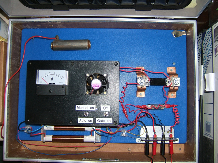 The two air-core coils are wound separately rather than bi-filar wound, and some experimentation with different types will be undertaken to see the effect on overall gas production. This circuit is shown in the following video, driving a 2.6 inch long pair of electrodes with a 2 mm gap between them, sitting in a test cell. The electrodes have seams and are made of an unknown quality of stainless steel and can be seen at the top of the photograph above. This video shows considerable gas production with almost no current draw and the cell staying completely cool. Running Electrical Generators on Water Alone After many decades of being lied to, most people believe that it is necessary to burn a fuel (typically, a ‘fossil fuel’ such as petrol or diesel) in order to make an engine run. ‘Scientific experts’ demonstrate their ignorance by proclaiming that their calculations show that there is just not enough energy in hydrogen released through electrolysis, to provide enough power to run an engine which can provide sufficient electrical energy to perform the electrolysis in the first place. Their calculations are completely wrong as they are based on a major level of ignorance of the real facts:
Interestingly, quite apart from the fact that generators running on water as the only visible fuel, have been powering off-grid locations 24 x 7 for many years now, and ignoring that little detail, check out this newspaper comment:  This is a very interesting comment from Vice Admiral Cullom. Firstly, he confirms that the Navy’s massive engines can be powered by gas produced by electrolysis. Second, he implies very strongly that refuelling with oil-based consumables is no longer needed, and that means that the electrolysis is well in excess of 100% efficient, making those massive engines self-powered. Third, it seems reasonable to presume that if those massive engines can be self-powered through electrolysis, that the very much smaller engines in cars could also be run on electrolysis, even if the same method of electrolysis were not used. Anyway, we have to deal with the tiny, very inefficient motors which are used in generators which normally use petrol as the fuel: In the UK, three men managed to run a generator on water alone, using just simple things which are within the scope of the average handyman in his workshop. They bought a standard petrol-driven electrical generator off eBay and managed to run it without using any petrol. They used a hydroxy gas flow which they measured at just 3 lpm and they test loaded the 5.5 kilowatt generator with 4 kilowatts of equipment. Afterwards they abandoned the generator and moved on to a much bigger engine as their plans are to sell electricity to the local power company. Their representative said: the equipment was put together by my associate, who supplied the water/electrolyte (not a standard electrolyte, 0.4% by volume). It was a 5 kW petrol generator (about 300cc). We attached a Chevrolet alternator which constantly charges a 12-volt 55 Amp-Hour battery, which in turn powers six HHO tubes, each of which draws 6 watts, for a total of 30 watts. The outputs of these electrolysers are connected in series and they feed the gas into a low-pressure butane gas “camping” tank which has an 18 psi pressure release valve. This tank feeds the air intake of the generator which is adjustable with a choke. We loaded the 30-amp socket of the generator with various drills, heaters etc. working, for more than four hours. The maximum load which we tried was 4 kilowatts, being a bar heater, a kettle and two drills. The electrolyser tubes are heavy-duty plastic (rated for 80 psi pressure). Inside are 4 tubes of stainless steel (3 positive and 1 negative). Each tube created 1 litre of gas every two minutes which is a total of 3 litres per minute. They eventually become warm to the touch, but they do not get hot.  In Broad Outline In order to achieve this objective, very much like Stan Meyer, we need to feed the engine three things:
 Here, they have opted to feed the hydroxy gas into the air system after the air filter (a thing which we normally avoid as it is not helpful for the hydroxy gas production efficiency, but the first step is to reproduce their successful method exactly before seeing if it can be improved further). Also fed into this same area is the cold water fog which is comprised of a very large number of very tiny droplets. The air enters this area as normal, through the existing air filter. This gives us the three necessary components for running the generator engine without using any fossil fuel. Creating the cold water fog There are three different ways to generate the spray of very fine water droplets which are a key feature of the success of this way of running the engine. One way is to use a Venturi tube, which, while it sounds like an impressive device, is actually very simple in construction:  It is just a pipe which tapers to a point and which has a very small nozzle. As the engine draws in the air/hydroxy mix on it's intake stroke, the mixture rushes past the nozzle of the Venturi tube. This creates an area of lower pressure outside the nozzle and causes water to exit through the nozzle in a spray of very fine droplets. Some perfume spray bottles use this method as it is both cheap and effective. An alternative method of making the cold water fog is to use one or more "pond foggers". These are small ultrasonic devices which are maintained at the optimum operating depth in the water by a float. They produce large amounts of cold water fog which can be fed into the engine like this:  A third method is to use a small carburettor of the type used with model aircraft. This does the same job as a regular engine carburettor, feeding a spray of tiny water droplets into the engine air intake. The physical arrangement of this option depends on the construction of the air filter of the generator being modified. Some Safety Features Up to this point, the electrolyser has been shown in bare outline. In practice, it is essential that some safety features are incorporated as shown here:  These safety devices should be familiar to you by now as they have already been explained earlier in this document. The Reason for Changing the Timing The fuels used with most internal combustion engines are either petrol (gasoline) or diesel. If you are not interested in chemistry, then you are probably not aware of the structure of these fuels. These fuels are called "hydrocarbons" because they are composed of hydrogen and carbon. Carbon has four bonds and so a carbon atom can link to four other atoms to form a molecule. Petrol is a long chain molecule with anything from seven to nine carbon atoms in a chain:  Diesel has the same structure but with eleven to eighteen carbon atoms in a chain. In a petrol engine, a fine spray of petrol is fed into each cylinder during the intake stroke. Ideally, the fuel should be in vapour form but this is not popular with the oil companies because doing that can give vehicle performances in the 100 to 300 mpg range and that would cut the profits from oil sales. The petrol in the cylinder is compressed during the compression stroke and that reduces its volume and raises its temperature substantially. The air/fuel mix is then hit with a powerful spark and that provides enough energy to start a chemical reaction between the fuel and the air. Because the hydrocarbon chain is such a large molecule, it takes a moment for that chain to break up before the individual atoms combine with the oxygen in the air. The main engine power is produced by the hydrogen atoms combining with oxygen, as that reaction produces a large amount of heat. The carbon atoms are not particularly helpful, forming carbon deposits inside the engine, not to mention some carbon monoxide (CO) and some carbon dioxide (CO2) as well. The key factor here is the slight delay between the spark and the combustion of the fuel. The combustion needs to happen a few degrees after Top Dead Centre when the piston is about to start its downward movement in the power stroke. Because of the delay caused by the hydrocarbon chain breaking down, the spark occurs a few degrees before Top Dead Centre: If you were to replace the petrol vapour with hydroxy gas, then there would be a major problem. This is because hydroxy gas has very small molecule sizes which do not need any kind of breaking down and which burn instantly with explosive force. The result would be an explosion which occurs far too soon and which opposes the movement of the rising piston as shown here: The forces imposed on the piston's connecting rod would be so high that it would be quite liable to break and cause additional engine damage. In the case of our electrical generator, we will not be feeding it a mix of air and hydroxy gas, but instead, a mix of air, hydroxy gas and cold water fog. This delays the combustion of the hydroxy gas by a small amount, but it is still important to have the spark occur after Top Dead Centre, so the ignition of the generator needs to be retarded by eleven degrees. Engine design varies considerably in ways which are not obvious to a quick glance at the engine. The timing of the valves is a big factor here. In the smallest and cheapest engines, the engine design is simplified by not having the spark timing taken off the cam-shaft. Instead, production costs are cut by taking the spark timing off the output shaft. This produces a spark on every revolution of the engine. But, if it is a four-stroke engine, the spark should only occur on the power stroke which is every second revolution of the output shaft. If the fuel is petrol, then this does not matter as the extra spark will occur near the end of the exhaust stroke when only burnt gasses are present in the cylinder. Some people are concerned when they think of hydroxy gas burning and producing water inside the engine. They think of hydrogen embrittlement and rusting. However, because of the nature of the hydrocarbon fuel already being used, the engine runs primarily on hydrogen anyway and it always has produced water. The water is in the form of very hot vapour or steam and the engine heat dries it out when the engine is stopped. Hydrogen embrittlement does not occur as a result of using a hydroxy gas booster. Anyway, if we were to delay the spark until after Top Dead Centre as we must, then the situation is quite different as the waste spark will also be delayed by the same amount. With most engines, at this point in time the exhaust valve will have closed and the intake valve opened. Our very flammable gas mix will be being fed into the engine on it's intake stroke. This means that our gas supply system is openly connected to the cylinder through the open intake valve, and so, the waste spark would ignite our gas supply system (as far as the bubbler which would smother the flashback). The situation is shown here:  this leaves us with two engine adjustments: timing delay and waste spark elimination. There are various ways in which these can be done and as each engine design is different, it is difficult to cover every possibility. However, there is a technique which can be used with many engines and which deals with both issues at the same time. Most engines of this type are four-stroke engines with intake and exhaust valves, perhaps something like this:  The intake valve (shown on the right in this illustration) is pushed down by a cam shaft, compressing the spring and opening the inlet port. The exact arrangement will be different from one engine design to the next. What is fixed is the movement of the valve itself and that movement only takes place every second revolution. There are various ways of using those movement to eliminate the waste spark and retard the timing. If a switch were mounted so that it opens when the intake valve opens and closes when the intake valve closes, then the switch closure shows when the piston starts upwards on its compression stroke and a simple electronic circuit can then give an adjustable delay before firing the coil which produces the spark. This, of course, involves disconnecting the original electrical circuit so that no waste spark is generated. The current flowing through the switch contacts can be arranged to be so low that there will be no sparking at the contacts when the circuit is broken again. The switch positioning might be like this:  An alternative is to attach a strong permanent magnet to the rocker arm, using epoxy resin, and then position a solid state "Hall-effect" sensor so that it triggers the delay before the spark is generated. If the engine did not have a waste spark, then in theory, the timing mechanism of the engine could be used to retard the spark. However, in practice, the timing mechanism is almost never capable of retarding the spark to the position that is needed for running without fossil fuel, and so, some kind of delay circuit will be needed anyway. The sort of delay circuit needed is called a "monostable" as it has only one stable state. A basic circuit of that type is:  If you are not at all familiar with electronic circuits, then take a look at the beginner's electronics tutorial as that explains how circuitry works and how to build any simple circuit from scratch. We can use two of these circuits, the first to give the adjustable delay and the second to give a brief pulse to the ignition circuit to generate the spark:  Making the hydroxy gas When the generator is running, we have a ready supply of electrical energy, coming from a piece of equipment which has been specifically designed to supply large quantities of electricity for any required application. We are not dealing with the spare capacity of some low-grade alternator in a car, but we have substantial electrical power available. Having said that, the electrolysers described at the start of this document are efficient and it is unlikely that an excessive amount of power would be needed when using one of those designs. Another convenient factor is that this is a stationary application, so the size and weight of the electrolyser is not at all important, and this gives us further flexibility in our choices of dimensions. As this is an application where it is highly likely that the electrolyser will be operated for long periods unattended, an automated water supply system should be provided. The main details of such a system have already been covered, but what has not yet been dealt with is the switching for the water pump. The water pump itself can be an ordinary windscreen-washer pump, and we need some form of switch which operates on the electrolyte level inside the electrolyser. It is sufficient to sense the level in just one of the cells inside the electrolyser as the water usage will be pretty much the same in every cell. If you make the electrolyser in a suitable size or shape, then a simple off-the-shelf miniature float switch can be used. If you prefer, an electronic level sensor can be operated, using two bolts through the side of the electrolyser as the level sensor. A suitable circuit for this simple switching task could be:  When the electrolyte level inside the electrolyser is in contact with the upper bolt head, the circuit is switched off and the water pump is powered down. The electrolyte has a low resistance to current flow, which is not surprising as we went out of our way to make sure that it has, and so it is short-circuiting the ten thousand ohm variable resistor VR1, and dragging the voltage at point A down to a low value which keeps the three transistors TR1, TR2 and Tr3, switched off and the relay powered down. When the electrolyte level falls below the upper bolt head, the voltage at point A is no longer pinned down to a low value and it starts to rise. This rise is delayed by the capacitor C so that minor ripples on the surface of the electrolyte do not keep tripping the circuit on and off in rapid succession. After a few seconds have elapsed during which the electrolyte has stayed below the upper bolt head, the voltage at point A rises far enough to trigger the circuit. Transistors TR1 and Tr2 are wired together in such a way that they switch on suddenly and change transistor TR3 cleanly over from its Off state to its On state, powering the relay and starting the water pump. When the water pump adds enough water to the electrolyte to bring the level back up to the upper bolt head, the short-circuiting effect of the electrolyte pulls the voltage at point A back down again and switches the water pump off again. The big advantage of this arrangement is that the sensor inside the electrolyser has no moving parts and there is not the slightest chance of a spark occurring between the bolt heads. This circuit can be built in many different ways: using screw-connector strips, a printed circuit board, stripboard, etc. A possible physical layout for this circuit is shown here: The following layout is based on the standard 10-strip, 39-hole strip-board, the underside of which looks like this:  For convenience in drawing, the holes are represented as the points where the lines cross in the diagram shown here:  The horizontal lines represent the copper strips and the intersections with the vertical lines represents the matrix of holes. Many different layouts could be used for this circuit, so the following diagram is only a suggestion:   The water-level control for the water supply to the pond fogger or Venturi tube misting device does not need any form of fancy mechanism. The standard ball-cock valve mechanism which is used with toilets is quite adequate, especially if a floating pond fogger is being used as it maintains its own optimum depth below the surface and so the overall depth is not in any way critical provided, of course, there is sufficient depth for the fogger to float correctly. Starting: When left for any length of time, the gas pressure inside the electrolyser will drop because the nature of the hydroxy gas alters. This means that there will not be sufficient hydroxy gas available to start the engine and no more gas will be generated until the engine drives the generator. So, to deal with this situation, a lead-acid car battery is included so that it can be switched in to replace the generator for a brief period before the engine is started. That inclusion gives this overall arrangement:  This arrangement is perfectly capable of running a standard generator without the use of any fossil fuel. A generator run like this has almost no harmful emissions as the only possible contaminant is a minute amount of lubricating oil escaping past the piston rings and being burnt along with the hydroxy gas. It should be noted that while no fossil fuel needs to be bought to run this generator system, the electrical output is far from free and is actually quite expensive as there is the purchase cost of the generator, the electrolyser and the minor additional equipment. Also, generators have a definite working life and so will need to be refurbished or replaced. It might also be remarked that if a generator of this type is going to be used in an urban environment, then the addition of sound-reducing baffles and housing would be very desirable. At this point in time I am aware of five different electric generators which have been adapted to run on water. At least four of these are from different manufacturers. The method of altering the timing and dealing with the waste spark is different from one adaption to the next. One user has altered the spark timing of his generator to after Top Dead Centre by rotating the timing disc to a position not envisaged by the manufacturer. The timing disc is held in place by a locking ("key") bar which fits into a channel cut in the shaft of the engine, matching it to a similar channel cut in the disc. The alteration was achieved by cutting a new channel in the shaft, allowing the timing disc to be positioned further around the shaft, producing the required timing delay. This arrangement also makes the waste spark ineffective and so it can be ignored. While this method requires the cutting of a slot, it does away with the need for any electronics and it is a very simple solution. If you feel that the construction of a suitable electrolyser would be a problem or that the amount of electric current needed to operate it would be excessive, let me show you the actual figures involved: Michael Faraday was an exceptional and highly respected researcher who investigated the electric current needed to convert water into hydrogen gas and oxygen gas by electrolysis. His results are accepted by pretty much every scientist everywhere. While he expressed the results of his work in terms which would be meaningless to the average person, his result is that an electrical input of 2.34 watts produces one litre of hydroxy gas in one hour. In practical terms, that means that a current of 0.195 amps at 12 volts will produce 1 litre of hydroxy gas in one hour. In passing, only a nearly discharged lead-acid battery would have a voltage of 12 volts as the fully charged state is 12.85 volts and a vehicle alternator produces about 14 volts in order to charge the battery. It is easier then, to compare the gas output of electrolysers directly to the figures produced by Faraday as shown here, based on a gas output of 15 litres per minute which is 900 litres per hour: Faraday: 900 litres in one hour, takes 2,106 watts or 100% Faraday Boyce: 900 litres in one hour, takes 998 watts or 211% Faraday without pulsing Boyce: 900 litres in one hour, takes 180 watts or 1,170% Faraday with pulsing Cramton: 900 litres in one hour, takes 90 watts or 2,340% Faraday Much of this is not very important as it has been demonstrated that a gas production rate of around 3 lpm (180 lph) is sufficient to run a generator which produces 5,500 watts. Let us assume that the measured figure is 100% wrong and that it takes 360 lph of hydroxy gas, plus cold water fog, plus air, to run the generator, then: Faraday would need 843 watts Boyce would need 400 watts without pulsing Boyce would need 72 watts with pulsing Cramton would need 36 watts None of these figures are important for running a generator because with an electrolyser efficiency of only 50% Faraday still leaves a massive generator excess of nearly 4 kilowatts on a 5.5 kilowatt generator. The gain is in running a generator as an internal combustion steam engine and not in the great efficiency of the electrolyser. It is distinctly possible that the pessimistic figures shown above are twice what is actually needed, but who cares? - the facts speak for themselves, with several people scattered around the world, already running generators on water. Many different generator designs have been adapted, typically, by modifying the flywheel, filling in the keyway and cutting another one to give a spark 2 degrees after TDC. Experience has shown that the 6.6 kVA Honda V-twin petrol motor generator and the Vanguard V-twin work very well long-term when adapted to run on water only. Wear and Tear Issues A man who lives in Alaska is very experienced in the use of renewable energy sources and unconventional fuel systems. His experiences are likely to be helpful for anyone who intends to use an electrical generator, whether running on water or on a fossil fuel. He recalls the experiences of a friend: He decided to live off-the-grid because it was going to cost him $20,000 to get connected to the grid and as his house was not that large, he decided to go the alternative route. We designed a system which would use a 4 kW inverter and have an 8 kW Briggs & Stratton generator with a 13 kW surge capacity, for back up. The system has 6 solar panels and a 24 volt battery bank with 400 amp capacity. Having long summer days here in Alaska, the solar panels have more than enough capacity for charging the battery bank on sunny days. However, but when the day is overcast or when it is winter when there are only six hours of sunlight, the battery bank does not get charged fully. At these times, the generator is used to top up the battery bank. American generators normally have either two or four 120-volt outputs each rated at 15 amps, plus one 240-volt output rated at 33 amps. If one of the two 120-volt outputs is used to charge the battery bank, then you get left with just the other 120-volt output for any other power needs during the time when the battery bank is being charged. This is not a satisfactory arrangement as operating with one field at maximum power and the other one lightly loaded or unused, causes a field imbalance in the generator, engine crank imbalance and ring or regulator failure within six months. It also causes noisy running and excessive fuel consumption. Run in this way, providing a 60-amp charge rate, the generator ran hard and loud for two to two and a half hours per day, and running it was costing $350 per month for gasoline. The generator failed after four months. In order to balance the loading on the replacement generator, a 15 kVA step-down transformer costing less than $1000 was purchased so that the 240-volt output could be used to drive 120-volt equipment. A transformer to be used for this needs to have a power-handling capacity which is greater than the surge capacity of the generator. A major advantage is that the generator current is halved for any given level of equipment current drawn because the equipment is running at only half of the generator voltage. Using this transformer made a massive difference, giving a balanced output and providing a 90-amp charging rate for the battery bank as well as having ample power to run other household equipment when the battery bank was being charged. The result was a charge time of just one hour twenty minutes per day, with the generator running quietly and smoothly. The fuel consumption also dropped to just $70 per month which is just one fifth of what it was, covering the cost of the transformer in under four months. This generator has been running now for two years without any problems at all. Selwyn Harris of Australia has kindly agreed to share detailed information on how he performs the conversion of a standard electrical generator to enable it to run on water alone. The generator which he uses as an example for this tutorial is a GX4000i generator: 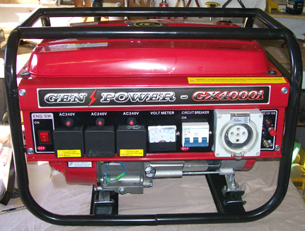 The supplier is AGR Machinery which is an Australian company on eBay which buys up stock from collapsed companies and resells the equipment. The supplier says: GX4000i portable type generators have smoother output power, comparable to public utility sources. Ideal for powering medium loads such as:
Features:
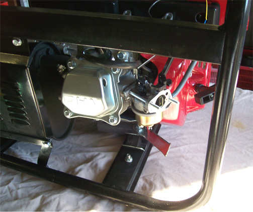 This allows access to the carburettor which is then removed as it will not be used: 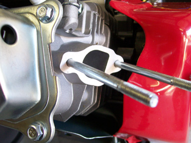 The next step is to construct a pressure-release valve mechanism which will protect the equipment from damage in the unlikely event of a major, sudden rise in pressure caused by the unwanted ignition of the HHO gas mix used to power the generator. For this, parts are purchased from the local hardware store. The brass fittings are a 12mm barrel, a 12mm female T-fitting and a 12mm to 9mm hose reducer as shown here: 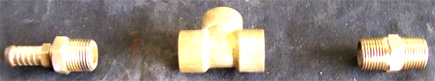 The PVC plastic fittings are a ½” to 1-1/4” reducer and a 1-1/4” End Cap, along with the roller ball from an old-fashioned mouse and a relatively weak compression spring to hold the ball in place during normal operation where the gas pressure is low: 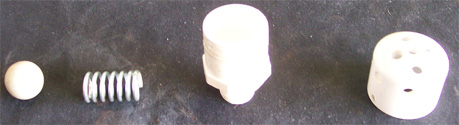 These components are then assembled to produce the pressure-release valve: 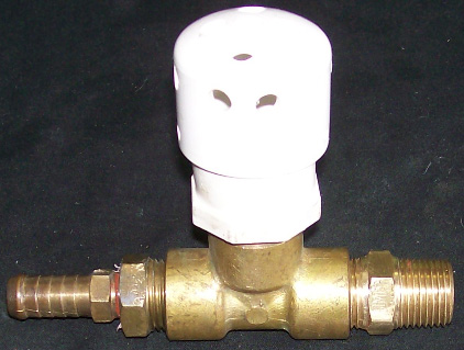 The inside of the flash-arrestor looks like this:  The ball is held in place by the spring allowing the HHO to flow past it, but if a sudden increase in pressure should occur, then the ball is forced upwards, opening a path to the many holes drilled in the plastic fittings:  When the gas pressure drops again, the spring pushes the roller ball down to seal off the pressure-release holes. However, Selwyn adds an additional spring-loaded valve to the arrangement. This one is there in case the electrolyser fails to produce a sufficient volume of gas in the event of a sudden increase in demand. This valve is marked as a “vacuum-relief” valve although, strictly speaking, it deals with reduced pressure rather than an actual vacuum. The arrangement is shown below. Please take note of the fact that Selwyn uses the Hogg style of electrolyser and that design has a bubbler built into it, so if you are using some other design of electrolyser, please be very sure to use at least one bubbler between the electrolyser and the engine, in spite of the fact that there is very little chance of the engine mis-firing and igniting the HHO gas in the electrolyser. For an engine of this size, an electrolyser which produces 4.5 or 5 lpm of HHO should be adequate. The addition of cold water mist through a Venturi tube as shown, both lowers the engine temperature and increases the engine power as the mist converts instantly to flash-steam when the HHO gas ignites, raising the pressure inside the cylinder and boosting the power output.  Next, a piece of ¼” (6 mm) thick aluminium plate is cut and shaped to the size of the carburettor gasket which is not a symmetrical item. This is done by tracing the gasket and transferring it on to the aluminium plate, drilling the holes and then cutting out the outline shape. The edges are then filed to create a nice fit on the engine port. 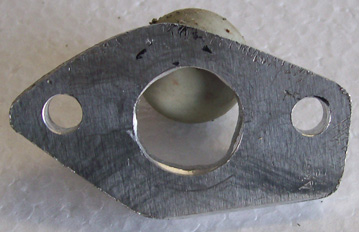 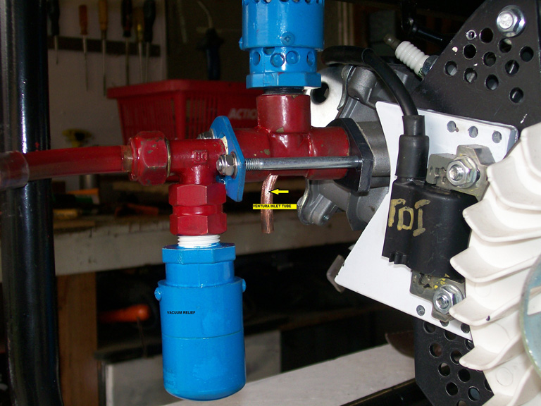 The pipes, backing plate, pressure-relief, vacuum-relief, gaskets, nuts and bolts are then assembled as shown above. Most of the pressure-relief valve components shown in the photograph have been painted, which happens to conceal the different materials being used. At this point an electrolyser of any design which can produce at least 4.5 litres of HHO gas mix per minute is connected to the intake. The electrolyser most often used by Selwyn is the Hogg design disclosed by him earlier in this chapter. 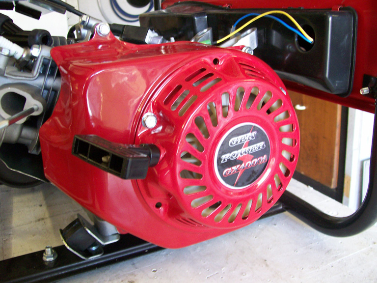 The manual Pull-start and the generator cover are now removed. It is only necessary to remove four of the bolts to take the cover off:  This is the engine with the starter pull and the blower cover removed. At “A” you can see the magnetic pulse type Transistor Discharge Ignition pick-up in it’s original position, bolted in place at 8 degrees before Top Dead Centre. This needs to be removed and an aluminium plate inserted to allow the TDI to be mounted in it’s new position. Because of the new fuel, it is necessary to retard the ignition system. This can be done in one of two ways, neither of which is particularly easy, so you may need the help of an engineering shop. The easiest way is to modify the installed ignition to Top Dead Centre. This is Selwyn’s aluminium TDI adaptor plate which he made from 2mm thick aluminium sheet:  In this picture, the outline of the fuel intake port is obscured due to it having been temporarily blocked off during the construction. The tools required for constructing these components are a drill press and a jig saw fitted with a metal blade. Selwyn used this timing alteration method on his own smaller generator which has run trouble-free for a year. The objective is to delay the ignition spark from 8 degrees before Top Dead Centre to either Top Dead Centre or to 1 degree after TDC. This allows for a good spark on the compression stroke and when the waste spark occurs, the inlet valve has not yet opened and so there is no HHO is in the ignition area. That is to say, the exhaust valve has just closed and the inlet valve has not yet opened. This results in a good compression stroke for the HHO and does not try to send the piston backwards due to premature ignition of the gas mix. The above picture shows the aluminium plate mounted and ready to accept the pick-up. This plate needs to have air holes drilled in it in order to allow cooling air to flow over the engine fins behind it. The TDI adaptor plate looks like this:  And as shown below, the support plate is drilled with the ventilation holes. In this photograph the adaptor plate is just resting on the support plate. Later, when the TDC timing position is established, the adaptor plate will be bolted to it using the three holes top and bottom on the white plate. This locks the timing to that setting and the timing is never changed. In 2010, when adapting a previous generator, an experienced mechanic was asked to establish the TDI plate position and he charged sixty Australian dollars for doing that.  Finally, the covers and the Starter handle need to be bolted back in place. Instead of paying somebody else to set the new spark timing, it is perfectly possible to do that yourself. One effective method is as follows: 1. Mark the casing of the engine in a convenient location as shown in yellow in this photograph: 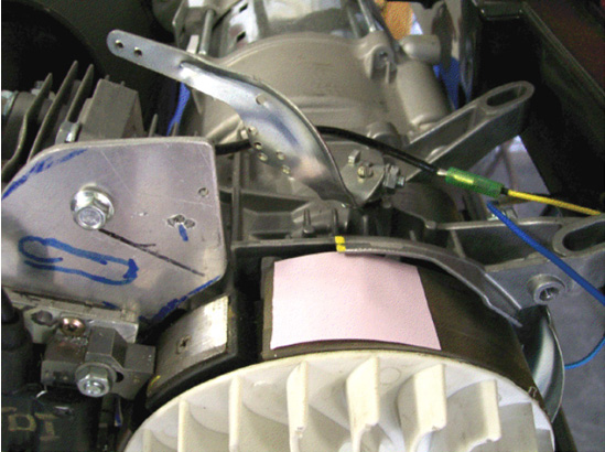 2. Remove the spark plug and insert a long screwdriver until the top of the piston is felt. Manually rotate the engine (clockwise for this generator as can be seen from the curved fan pieces on the flywheel) until the screwdriver is no longer pushed upwards. It may take more than one rotation to find this point accurately. When that point is found, mark the flywheel directly in line with the casing mark which you just made. This marking needs to be very accurate. 3. Continue rotating the flywheel very slowly until the screwdriver starts to go down again and mark that point on the flywheel. Again, this marking needs to be very accurate. 4. Measure the distance along the flywheel between the two flywheel marks which you have just made and then make a larger mark on the flywheel exactly half way between your two marks. If accurately done, this new point is where the flywheel is when the piston is exactly at Top Dead Centre, which is where we want the spark to occur. This marking on Selwyn’s flywheel is like this: 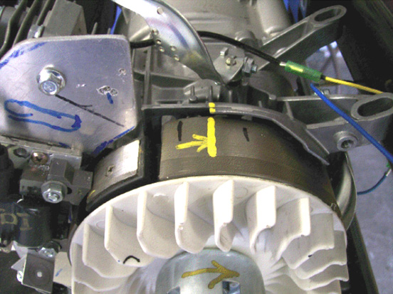 5. Next comes a bit of arithmetic. The diameter of the flywheel is 180 mm which means that it’s circumference is 3.14159 x 180 = 565.5 mm and as there are 360 degrees in each rotation of the flywheel, then the outside edge of the flywheel will move 1.57 mm for each of those degrees. The engine specification states that the spark timing is 8 degrees before Top Dead Centre and we want the spark to occur exactly at TDC, which means that we want 8 x 1.57 = 12.5 mm of the flywheel circumference to have passed by before the spark occurs. 6. To achieve this delay in the spark timing, the TDI needs to be moved 12.5 mm in the direction which the flywheel rotates. You will notice that for this major timing change, the TDI adjustment is very small, only half an inch. 7. When the TDI adjustment has been made, the timing can be checked using an automotive timing light connected to the spark plug lead. The engine can be spun using an electric drill. As the flywheel is spinning fast and the flash of light from the timing light is very short, it makes the flywheel mark appear to be stationary in spite of the fact that it is passing by very rapidly. If the TDI adjustment is correct, then the central mark made on the flywheel will appear to be stationary and exactly aligned with the mark made on the casing. This is exactly what happened when Selwyn’s motor had it’s timing adjusted, but the important factor is to have the spark close to the Top Dead Centre point to make sure that the inlet valve is fully closed before the spark occurs. Two degrees after Top Dead Centre is a popular point for the spark with many of the existing generator conversions which I have been told about, possibly to reduced the loading on the piston’s connecting rod. Here is a photograph of Selwyn’s latest generator conversion having it’s new spark timing checked out: 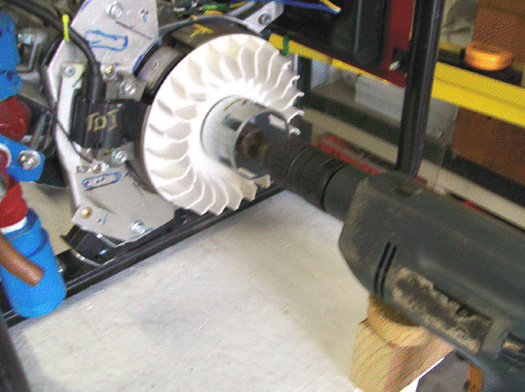 8. Most small petrol engines have the spark timing set between 8 degrees and 10 degrees before Top Dead Centre. If it so happens that you do not know what the timing of your particular generator is, then complete the flywheel marking procedure of step 4 above, but make three additional marks on each side of the TDC mark. Space those marks 1.5 mm apart as they will then make a scale which shows each degree from 3 degrees before TDC to 3 degrees after TDC. When the timing light is used, it then shows exactly where the spark occurs and if the engine had an original spark timing which was not 8 degrees before TDC, then the scale shows immediately how much further the TDI needs to be moved to set the spark exactly where you want it to occur. The Cold Water Mist Getting the fine droplets of water into the engine can be done two different ways. The first way is to use a Venturi tube which generates a fine spray of droplets when air moves rapidly past a small water-filled hole. You may not have noticed, but this method has been used extensively in perfume sprays and it is very effective. Selwyn describes how he constructs a Venturi tube: A short length of 1/4” (5 or 6 mm) diameter copper tubing is used. This is generally available as central heating supplies and if there is any difficulty in finding some, then your local garage can probably direct you to a supplier (if they don’t just give you a short length from their own supply).  The copper pipe is then heated with a plumber’s gas torch and bent very slowly and carefully to the shape shown above. Some people find it helpful to insert a length of suitable flexible material into the pipe before starting the bending – something like the coiled steel spring material used to support net curtains – as that helps to keep the copper pipe from kinking when being bent. Next, the end of the copper pipe which will form the nozzle, is filled with silver solder and the end filed flat. Then, a small hole is drilled through that silver solder plug. The smallest possible drill bit should be used for this, although the hole may need to be drilled out to a slightly larger diameter, depending on what the engine requires (which is found by successive trials):  This Venturi tube is to be inserted into the last brass fitting before the engine, so a 1/4“ hole is drilled through the brass and then the drill is removed very slowly at a slight angle, the angle of drag being down the axis length of the brass fitting. The copper Venturi tube is then inserted through the hole and positioned so that the Venturi hole is aligned up exactly with the centreline of the brass fitting and positioned exactly in the middle of the cross-section of the brass fitting and then soldered in place:  The method which Selwyn uses to block off the end of the copper tube with silver solder is to seal the far end of the tube with tape and fill the tube with fine-grained sand like this:  And then the tube is heated with the gas torch flame and the solder run into the tope part of the tube. When the solder has cooled, the tape is removed and the sand removed by tapping the tube. When the hole has been drilled through the solder, air is blown through it to dislodge any remaining sand, and then water is forced through the hole. As the tube is short, any remaining sand can be removed with a pipe-cleaner or any similar slender cleaning device. The installed Venturi tube can be seen here:  The second way to introduce cold water mist into the airstream entering the engine is to use a commercial “pond fogger” which can be bought at pet supplies outlets. These have to be powered electrically and housed in their own water container. Some of the more advanced versions float on the surface of the water so that the fog-generating section is always submerged to the ideal operational depth below the surface of the water. The generator should run well with 5 lpm of HHO gas plus cold water mist. Any design of electrolyser can be used. However, when used with rainwater, the Hogg electrolyser will draw about 1.4 amps per cell, giving a total input of about 115 watts when run on a 12-volt electrical supply. While rainwater is supposedly pure, the reality is that it seldom is and it’s ability to carry a current varies dramatically from place to place and even more widely from country to country. However, regarding the water, Selwyn says: The water I use is treated in a special way to make sure that the electrolyser runs at the lowest temperature and amperage possible. For this, using rain water is a must and the rain water coming off a steel roof is the best. The water is then treated by inserting a double coil of stainless steel wire into a volume of about 5 litres of water. A supply of 12-volts DC is applied to the coils, and the resulting current allowed to run through the coils for about 5 hours. This results in hot and very dirty water. The water is then filtered using a 0.5 micron filter making the water ready for use in the electrolyser. If more water is needed, say 30 litres, then leave the coils running for at least 24 hours. I use an old 35 litre beer keg and prepare 30 litres at a time. A major reason for doing this is to remove all the solids suspended in the water so that they will not clog up the stainless steel mesh inside the electrolyser. After the construction of the Hogg electrolyser is completed, then the stainless steel mesh electrodes need to be treated and cleaned. For this I use distilled water and fill the electrolyser enough to cover all the plates, and then add 1 packet of citric acid for each 3 litres of water used to fill the electrolyser. I got the citric acid from www.hho-research.com.au which is an Australia-only supplier and each packet has about 22 grams of citric acid in it:  The pumps are then run for about an hour after which the Hogg tubes are washed out completely with distilled water and then allowed to dry completely. This removes any residue from the stainless steel mesh electrodes, making the gas production rate much greater. I use an ordinary car battery to generate the HHO gas needed to start the generator running, after which, a standard battery charger powered by the generator output is used to keep the starting battery topped up. Please Note: This document has been prepared for information purposes only and must not be construed as an encouragement to build any new device nor to adapt any existing device. If you undertake any kind of construction work, then you do so entirely at your own risk. You, and only you, are responsible for your own actions. This document must not be seen as an endorsement of this kind of generator adaption nor as providing any kind of guarantee that an adaption of this kind would work for you personally. This document merely describes what has been achieved by other people and you must not consider it as being a foolproof blueprint for replication by anyone else. There are two YouTube videos which show a generator being operated on what appears to be just hydroxy gas alone: video 1 and video 2 and while the operation does not appear to be anywhere close to full power, the addition of cold water mist would probably make a major difference to the performance, but it does demonstrate that a generator can certainly be run without using any fossil fuel. The spark circuit in the first video appears to be powered by a small mains unit, but as the generator is lighting a powerful lamp, that electrical input could almost certainly be met by the output from the generator when it is running. Running an Unmodified Generator on HHO The reason for the modification of standard generators as shown above is due to the fact that the HHO gas mix produced by an electrolyser, ignites about a thousand times faster than a hydrocarbon fuel, and because of that, the spark which ignites the fuel needs to be delayed. That mechanical adaption of the generator can be avoided if the HHO gas mix is modified so that it ignites more slowly. This can, and has been done. David Quirey of New Zealand has been operating an unmodified generator and a welding torch on the HHO output from his 6 lpm own-design of electrolyser, for many years now. Henry Paine’s US Letters Patent No. 308,276 dated 18th November 1884, states that HHO gas can be converted into a more convenient gas which is much easier to handle, by the simple process of bubbling it through a suitable liquid such as turpentine or linseed oil. Although unaware of Henry Paine's patent, David discovered the technique independently and he has extended the technology further so that the gas ignition speed can be set manually. One important point which David stresses is that it is essential that the HHO coming from the electrolyser is passed through an ordinary bubbler containing water, before it passes through the second bubbler containing the modifying liquid. David finds that the lighter liquid, acetone, works better than the liquids suggested by Henry Paine although white spirit, carbon tetrafluoride, aviation fuel, hexane or even petrol can be used and any of them will slow the flame speed right down to that of butane. If the flame is being used for a specialist task such as jewellery making or glass blowing, then there may be an advantage in using one particular modifying liquid. Please note that the bubbler holding the acetone needs to be made of stainless steel as acetone can dissolve some plastics. David has further modified the characteristics of the output gas by adding in a percentage of the unmodified HHO gas. Although it is actually, subtle and sophisticated, David’s overall system is easy to understand. The ratio of the two gasses is adjusted by the settings of the two control valves as shown here:  Adjusting the ratio of modified HHO to unmodified HHO allows a high degree of control over the characteristics of the resulting gas mix. Added to that, David has developed an electronic control system which oversees and manages the gas flow rate according to the user’s needs at any given moment. The result is a system which allows water and electricity to be the means of supplying a gas which can be used as a safe, general purpose fuel. If it is used to run a generator, then the system appears to become self-powered if part of the generator output is used to drive the electrolyser. It should be possible to substitute the modified gas mix for propane or butane and so operate a wide range of existing equipment for heating, cooking and/or lighting. David runs a 4 horsepower Honda generator using this system:  The generator runs very well for David, however, I suspect that if cold water mist were introduced into the incoming air, then the power output would be increased due to the mist turning into flash-steam and providing greater pressure on the piston during it’s power stroke. Alternatively, it might be possible to match the present performance with a lesser gas flow rate, possibly powering a much larger generator if that were a requirement. It needs to be understood that David uses electronics which manages and controls the gas flow volume, suiting it to whatever the needs are at any given moment. Consequently, it is probable that the six litres per minute which David’s electrolyser can produce, is not actually used for most of the time. David also does welding, brazing and cutting with the same modified electrolyser gas mix which can provide adjustable flame heat and a flame length of anything up to two feet in length:  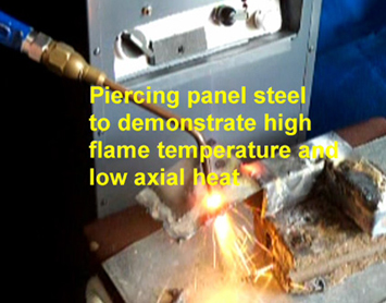 It is a good idea to use a proven design with full control electronics. David can help here with detailed step by step construction plans and instructional videos. 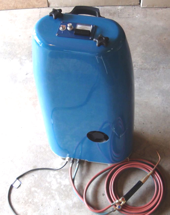 You can contact David for information on what is available to help you at the present time as his e-mail address is in the pdf version of this chapter. When using the system for welding, David uses the mains to power the electrolyser, the arrangement being like this:  The flashback arrestors are a sand-filled design and so are mounted vertically. The gas production rate is knob controlled using this circuit:  The first part of David Quirey’s circuit acts very much like a dimmer light switch. The 230-volt AC mains is fed through an On/Off switch and then an ordinary mains fuse. The current flow on through the circuit is blocked by the BT139 triac until it receives a pulse from the db3 diac (which is a component specifically designed to feed pulses to a triac). As the voltage builds up on the 68 nanofarad capacitor it eventually reaches the point at which it triggers the triac, which then switches on and remains on until the mains voltage drops down to zero again. The 500K variable resistor sets the rate at which the capacitor charges up, and so it controls the length of time that the triac is on in any given second (and so, the level of power fed onwards to the rest of the circuit). This happens on both the positive-going half of the AC waveform and the negative-going half of the mains sinewave voltage supply. Both the diac and the triac operate with AC and trigger either 100 or 120 times per second depending on the frequency at which the local mains runs. The current flow is then passed to a bridge rectifier in order to convert the AC into pulsing DC and the capacitor C1 which is 400-volt rated, smoothes the resulting DC. David’s cell has a large number of plates and so, operates off the 300 volts produced by this system. The ammeter between the diode bridge and the cell indicates the current flow and so, the amount of gas being produced at any given moment. The flashback arrestors are constructed as shown here:  Sincere thanks are due to David Quirey for freely sharing his design and experiences, and for his willingness to provide direct additional support and further details should they be needed. Stan Meyer's Water Injection System. While the above simple adaption will work for an electrical generator which is stationary and which is designed to provide large amounts of electrical power, some of which can be used for producing hydroxy gas from water, it is much more difficult to run a large capacity petrol/gasoline engine continuously with just water as the "fuel".  For larger engines aimed at producing mechanical output, we need a more powerful system, such as that developed by Stan Meyer of America. Although many years have passed since the sudden, highly suspicious death of Stan Meyer, as far as I am aware, his design has not been replicated, mainly because people do not understand the information which he left behind. However, recently, a man whose forum ID is "H2Opower" has helped explain what Stan meant, and much of the following description is down to his sharing his understanding publicly and freely. Stan's Canadian patent 2,067,735 has an arrangement where the injector schematic shows the injection into the engine of three separate components:  One component is described as ionised gas and ambient air is mentioned. The second component is part of the exhaust gas which is hot water vapour fed through a limiting valve, referred to as "inert gas". The third injection component is a very fine spray of water droplets or cold water “mist”. This three-component mixture is passed between high voltage electrodes and if the mix does not ignite spontaneously, then it is ignited with a spark. One version of Stan's recommended injectors for an existing engine are shown like this:  This is a cross-section which only shows two of the three gas inputs flowing through this injector/spark plug. Each gas input has it's own feed passage which leads out between the central electrode and the circular outer electrode, and each feeder tube has it's own one-way valve to prevent the power stroke from forcing the incoming fuel back up it's feed tube. This is only one of the ways that Stan shows that it can be done. Here is his diagram for a two cylinder engine fuel input, although it applies equally as well to any number of cylinders:  Let me stress that this is just an explanatory diagram and you do not have the intake and exhaust valves open when the spark plugs fire. Also, the pistons do not go up and down together but their movement is staggered to give a less uneven drive to the crankshaft. The point to note here is that the fuel intake is through standard valves and ordinary spark plugs are shown. However, this diagram for US Patent 5,293,857 is based on the use of an electrolyser and Stan found a way to avoid the need for an electrolyser. For this, Stan's "Gas Processor" is a really key device in spite of it being what appears to be a fairly simple construction. It operates by pumping light energy into the fuel components. This may not sound like a big deal but it most definitely is, in fact, it is the heart of Stan's system. In addition to the extra energy, the fuel components are also stressed by high-voltage pulsed DC applied in such a way that it tends to pull the molecules apart as they flow past into the engine. The Gas Processor is constructed from two highly reflective metal cylinders, 96 Light-Emitting Diodes ("LEDs") and a carefully adjusted high-voltage pulsed DC source. The reflecting tubes are used to make the light bounce backwards and forwards indefinitely until it is absorbed by the passing molecules. The choice of LEDs is very important as the wavelength of the light needs to be matched to the resonant frequencies of the fuel components passing by. Laser LEDs can be used but they need to be angled slightly in order for them to bounce and completely fill a section of the Gas Processor gas passage. The operation is simple in concept. Six banks of sixteen LEDs are installed in the outer cylinder which has a polished inner surface. To see the effect of each LED, consider just one LED on it's own:  The LED light shines on to the inner tube which has a highly polished outer surface. In the diagram above, the light is shown in red, and the uppermost LEDs of the six columns of LEDs can be seen. The light is then reflected back to the outer cylinder again:  The reflected light is shown here in yellow although it is identical in wavelength to the section shown in red. This reflected light is again reflected by the outer tube and that repeats over and over again until the whole of the area between the two tubes is completely filled with the light. This will happen with just one LED, and that light will continue to be reflected backwards and forwards indefinitely if it does not collide with a gas molecule. That is the effect of just one LED, but there are six LEDs at that level, each producing light of the same frequency and reinforcing the power of each of the other five LEDs, producing a very powerful overall band of light. The same thing happens in the vertical plane with the light bouncing all the way down the tubes, and as the LEDs at different levels generate different wavelengths, there is a powerful interaction between the different frequency waves, producing intermediate frequencies by a process with the technical name of "heterodyning":  In this diagram it has not been possible to show the way in which the reflected light from each LED interacts with the light from all of the other LEDs, but there is a complete intermixing of the beams. The LEDs are shown with greatly exaggerated size and spacing in order to give a reasonably understandable diagram. The diagram above, barely indicates the level of light intensity inside the Gas Processor, and that is from only six of the ninety six LEDs actually installed. It is a little difficult to visualise this device, but the gas (of whatever type) flows up through a circular doughnut-shaped space between two pipes and is hammered by a very high level of light energy of the appropriate frequency. "H2Opower" believes that the optimum LED frequencies are as shown here:  and while, not surprisingly, I have not been able to find an LED supplier for these exact frequencies, most LEDs emit a band of frequencies rather than just a single frequency, so the working LEDs need to include the frequencies shown here. The operation of the Gas Processor is further enhanced by applying a pulsed high-voltage between the inner and outer metal cylinders. This voltage stresses the molecules of the gas flowing between the two cylinders and because it is pulsed, it applies a tugging action on the molecules, tending to pull them apart:  As with all high-power free-energy systems, having the device operate in resonance is very important. If it is still available, the excellent video produced by "H2Opower": here shows what resonant circuit operation is all about. Briefly, the frequency of the driving waveform passing through winding "A" in the diagram above, is adjusted until almost no current flows through that winding. This is the same as tuning a radio to a particular radio station - in both cases, the signal at that frequency finds it almost impossible to drive any current through the winding. This would make you suspect that almost no current would flow in the output winding, but that is not the case because that current flows into the secondary winding from the local environment (after all, here is no electrical connection between the two windings, so common sense tells you that the electrons flowing in winding "A" do not flow out of the other winding). This resonant operation gives you a major energy gain courtesy of the local environment. The objective of the Gas Processor is to modify whatever gas is flowing through it, air, water vapour, hydroxy, or whatever, to one of it's highly charged, highly energetic states. The high voltage applied to the metal cylinders of the Gas Processor does not flow through the gas between the cylinders. Instead, it provides a very high electrostatic Plus charge on the outer cylinder and a very high Minus charge on the inner cylinder, and these two opposing charges pull the charged parts of each molecule towards themselves. The positively charged gas ions get pulled towards the Negative inner cylinder and the negatively charged gas ions get pulled towards the Positive outer cylinder. Stan uses this technique on the incoming air when he uses an electrolyser to power an engine:  However, Stan's preference is to use air, water mist and some of the exhaust gas from the previous power stroke to power his engines. This is an effective method as "H2Opower" states that he has blown part of a car engine clean through the bonnet of the car, and that indicates that there is plenty of power available from those three components (although, ideally, you want to get the timing right and not over-stress the engine!!). One thing that "H2Opower" points out is that the injectors supplied for converting any car to run on alternative fuels such as natural gas, can be adapted to be the equivalent of Stan's specialised injectors, if a pair of high-voltage electrodes are added to each injector and fed from a pulsed circuit such as Stan's "Voltage Intensifier Circuit". The arrangement would then be like this:  A 220-page "Technical Brief" from Stan Meyer here can be downloaded free, although it may well provide you with more information than you ever wanted to know about the subject. Peter Lindemann has shown that a much simplified version of Stan’s injection system can operate small engines directly on water alone. Let me suggest that it is not the water which causes the explosion, but instead, that the high-power spark causes disassociation of some of the water vapour, producing hydrogen and oxygen which then ignite, turning the remainder of the water vapour into flash-steam, making the engine operate as an internal combustion steam engine. The video shows a lawnmower engine operating on a spark which occurs ten or eleven degrees before Top Dead Centre:  Developed in conjunction with the EnergeticForum, the technique is based on the Aaron/Gotoluc style of operation with the circuitry shown in this video although the “DirectHits” spark-booster shown here might well make the circuitry easier. Obviously, using this technology to operate a standard electric generator would be a major objective, especially since there appears to be little need to adjust the existing spark timing much. Peter Lowrie of New Zealand developed an electrolysis system for use with internal combustion engines. Like the previous systems, Peter feeds a spray of fine water droplets into the engine, using a carburettor, supplied by a water tank. He also feeds in some exhaust gas and heated hydroxy gas, which is a technique which is almost identical to Stan Meyer's method. Peter also produces a very large volume of hydroxy gas with a most unusual method. He uses a delta-wound, GEC marine alternator (though he says that the alternator from a truck would do). He modifies the alternator by removing the diodes inside it and leading each of the three phase-windings out to his electronics. He uses each of the three phase-windings to power one electrolysis cell. He applies only 2 volts or so, to the DC winding of the alternator, which is about the minimum which allows the alternator to work. The DC current supplied is less than one amp while the pulsed current to the electrolysis cells is much higher. When a snap-on ammeter surrounds the wires to the cells, a current of at least 800 amps is displayed. A point of particular interest is the inductor (coil) placed between the electrolysis cells and the windings of the alternator. Peter describes this as a choke out of a 3-phase industrial power supply. It is comprised of a laminated steel core with a sheet of copper wound around it. This is remarkably like the arrangement used by Stan Meyer and already described earlier in this document. Peter has run a 1,600 cc car engine at 5,500 rpm with the gas output from his cells. He believes that his method of cascading the gas output from the cells through each other, produces a more active form of hydroxy gas. He also uses a heat-exchanger which allows the exhaust to pre-heat the hydroxy gas before it is passed to the engine (a method also used by Stan Meyer for running a car on water alone). Peter also uses impulse-operated valves to control the flow of gas to the engine as shown here:  The use of water in engines. I can fully understand someone having difficulty with accepting the idea that water can be used as part of the fuel inside an internal combustion engine. However, there is an old saying that "fact is stranger than fiction" and that certainly appears to apply in this case. First, it is essential to accept the fact that it can be an important component inside the engine, as this has been demonstrated by several different people who do not know each other and who live in different countries around the world. Second, having accepted that fact, the next step is to ask what exactly happens with the water. I have come across an interesting document dated May 2009. I have been unable to trace its origin in order to ask permission to reproduce it here, so if you know how to contact the author, then please let me know. This is a report on an actual experimental tests on an internal combustion engine: Ambient heat into work conversion. Water-steam car, simple concept: simple Otto engine running from water mist using standard off-the-shelf ultrasonic humidifier (4 stroke diesel engine will work as well...could even perform better).  website
Replication log: Ultrasonic humidifier 0.25 litter water vaporisation per hour was set to 1/3 of its power. Use the water humidifier at air intake. Remove carburettor (or injection stuff if any) and filter for first. The way from duster to the engines air intake should be as short as possible to avoid the micro water droplets created by the humidifier collecting on the inside of the tube which feeds the water mist to the engine air intake. The engine used was a 1-cylinder 200 cc electrical generator. The engine ran very slowly at first. In the case of a 4-stroke Otto engine, it is possible to speed it up using a propane cartridge. The engine then tends to "lock" into a higher rpm band, where the propane can be cut off permanently. The air going into the engine has a temperature of 22° C, while on average the air temperature leaving the engine was -16° C ( a 38° C drop). This is amazing – but this concept really does work! You can make the car engine idle using this method. The water may need to be a bit warm. Ignition is not needed but it does facilitate the engine running. You may need to “turn the key” several times (based on this replication test). In the case of a diesel engine, you may need to replace the injectors with some kind of spark plug like on an A.E.R.O.P.S engine or use Firestorm plugs or any other stuff which is able to give the water an additional blast via plasma discharge, to increase performance further. You can make a gasoline generator work with water steam, also a lawn mower, etc. Now – when it idles you have gone ‘over the edge’ so you need to add some more power, possible options are: adding hydrogen or HHO, preheating the water (possibly with solar energy), adding some fuel or spirit, powerful ignition or maybe some magnetic polarisation. This concept is now public and you can experiment with it on your own. Follow safety precautions and use common sense. Do not expect high rpm results on the very first test run. Its a very basic concept which shows just one kind of transformation of environment heat into pressure and usable work. Also, do not pre-heat the engine before using it. The engine must not be hot! A bit of physical background: During the first stroke of a 4-stroke Otto engine, the piston moves down and sucks ambient air into the cylinder. During the second stroke, the piston moves up and compresses this air to a pressure of 25 bar (atmospheres). According to the “ideal gas law”: the temperature rises due to compression above its initial ambient temperature. The compression ratio of the engine will boost the temperature, typically up to 450°C to 500°C. This second stroke of an Otto engine NEEDS ENERGY FOR COMPRESSION! Now consider what will happen to microscopic water droplets contained in the air inside the cylinder. If the water converts instantly to flash-steam, then its volume increases dramatically, boosting the pressure inside the cylinder and powering the piston during its power stroke and storing energy in the flywheel. Please note, that the water mist isn’t water vapour...it’s not a gas! It is still a liquid! The important DIFFERENCE becomes evident during the compression stroke! As the piston starts to move upwards to compress air which contains the water droplets, pressure AND HEAT, as described before, start to rise. BUT the compression itself is NOT able to raise the water temperature directly, as the water is still a LIQUID and therefore the temperature of the water isn’t affected from higher pressure! So initially, only the air temperature rises due to compression. But tiny water droplets are present inside the cylinder, and as the air temperature gets greater and greater than the temperature of the water droplets, heat starts to flow from the air into the water droplets, heating them up! But as long the water temperature does not reach its boiling point, the droplets will not expand due to this rise in temperature and they will simply keep the same volume. So the water droplets acting as a heat-absorber during the compression stroke! Lower heat implies lower pressure, and lower pressure during the compression stroke implies ENERGY SAVING DURING THE COMPRESSION STROKE! Please have a look at the following graph (no losses are included in the calculation):  The graph shows the pressure within a 4-stroke engine cylinder in respect of time, starting from the beginning of the compression stroke (second one), ending with the end of the power stroke (third one). The work that is needed for the compression stroke is represented by the integral of the graph, from the very left to the yellow marker. The work which is done by the piston during the power stroke is represented by the integral of the graph from the yellow marker to the very right of the graph (20,000 at the time scale). Let's assume that engine is an ideal one (loss-less). The red graph line represents the pressure within engine cylinder, if no water is present, and no ignition occurs. The graph is symmetrical to the Top Dead Centre (the yellow marker in the middle), so we put in energy at compression and we get the same amount back during the 3 stroke (power stroke). No loss, no gain. We get plus and minus zero. The blue graph line shows what happens, if microscopic water droplets are present. The pressure does not rise as much as in case without water droplets, because the water works as a heat absorber during the compression stroke, and this lowers the pressure as well. The shape of the graph changes, so that symmetry of the compression and power strokes isn’t there any longer, resulting in a gain of energy. Factors which affect this process include the water droplet diameters, droplet distribution, the engine's rpm which controls the length of time, the ambient air temperature, the engine's compression ratio and even the water hardness and it's physical properties. It is certainly not a simple case where you can say “more water, means higher revs giving more power”. For example, if the water droplets are too large, then there will be too little conversion to steam and insufficient power will be produced. Alternatively, if there are too few water droplets, then there may ne no effect at all or the conversion to steam may take place too early to provide useful power. The theory given here is a very simplified one, but should suffice for the first steps towards a better technology and a better understanding of the concepts of “energy from the environment”. It is tempting to conclude that the power gained from water droplets inside an engine cylinder are caused by the water turning into flash-steam and nothing else. However, that is probably not the case, nor is it the case that energy placed in the water by the sun heating it is extracted (which does happen) and that is the only additional source of energy. In the scientific paper entitled "Possibility of Liberating Solar Energy via Water Arc Explosions" by George Hathaway and Peter Graneau, they discovered that when they produced an electric arc discharge in cold water fog: "The principal discovery made in the past two years was that it is a collection of fog droplets in the water which explodes and not the liquid water itself. The term 'fog' is meant to include not only the tiny droplets which float in air but also larger droplets which fall in the atmosphere and would be more correctly described as 'mist'. The sole explanation of the explosions so far put forward contends that the intermolecular bonding energy in fog is less than 540 callg, the latent heat of bulk water. The bonding energy difference is then liberated in a quantum jump when the fog is formed in micro-seconds". Summing up their experiments, they conclude that "virtually all the kinetic energy developed by the explosion must be internal water energy" In the earlier scientific paper "The Anomalous Strength of Cold Fog Explosions Caused by High-Current Water Arcs" by N. Graneau, he comments: "The unusual strength of explosions caused by a pulsed current flowing through water plasma was first noticed in 1907 by Trowbridge in his early high-voltage laboratory at Harvard University. When he passed as arc through a spray of water, the resulting explosion was louder than in ordinary laboratory air. During the Second World War, Frungel measured the strength of water arc explosions and published his results in 1948. He concluded that they were not caused by heat and steam and freely admitted that he was unable to explain the phenomenon. In 1969, the US Bureau of Mines issued a long report on their investigation into using water arc explosions for rock fragmentation. In one experiment, the investigators at the Twin City Mining Research Centre noticed that the energy output was apparently 156% of the input. This result was reported but treated as an experimental error". The bottom line appears to be that using cold water mist droplets in an internal combustion engine has a minimum of the following energy additions:
5. Other Useful Devices The Panacea video series is highly recommended as being an excellent, practical demonstration of road-tested vehicle improvements. The Vortex Air-feed system Ted Ewert has developed and tested a very effective and simple device which can improve the running of some vehicles. This device works best with four-cylinder vehicles because the pulsed air intake of vehicles with fewer cylinders, enhances the beneficial effect. This is a silent, simple and cheap device which enhances the airflow into the engine. This can have a dramatic effect on the performance of the engine. For example, Ted has an old Datsun 310 which has been sitting unused for years. Gasoline loses it’s lighter fractions in six months or so and that makes it far less volatile and more difficult to burn. Ted’s Datsun has gasoline in the tank which is five years old and the car will not run on that fuel with it’s normal air intake. However, when Ted put one of his turbines on it, it starts immediately and runs fine with that old fuel. That particular vortex turbine has been dubbed "The Respirator". The Datsun has a carburettor which shows that this turbine works well with carburettors. 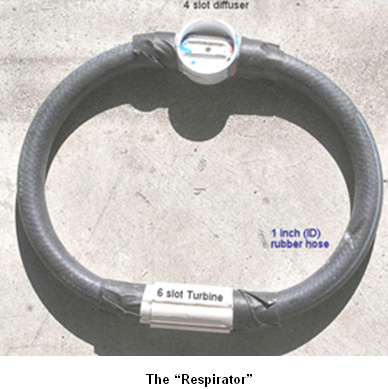 This simple device is a vortex tube made from a short piece of PVC pipe which has been slotted and shaped. It fits between the air filter and throttle body, or carburettor, and causes the incoming air to spin at a relatively high rate, creating a vortex. Angular velocity is crucial in the formation of a strong vortex and the air entering the Respirator from the air filter, arrives at right angles to the turbine slots, giving an immediate and powerful spin inside the tubing. Ted says: “Most people think of a spinning air mass as having no particularly unusual properties. This is not correct. A spinning air mass has some very unique and useful properties. Standard aerodynamics, and linear Newtonian physics are unable to explain the properties of a flow of air spinning at high speed. In fact, when compared to a static flow of air within a pipe, a vortex behaves in almost completely the opposite way. All spinning objects, whether they are solid, liquid or gaseous, contain two opposing forces: centrifugal and centripetal. Centrifugal is the expanding force travelling away from the centre axis, and centripetal is the contracting force pulling in towards the centre. This concept of dual forces is key to understanding a vortex. "Modern" physics has decided that the centrifugal force doesn't exist and now refers to it as a ‘false’ or ‘phantom’ force. This illustrates how detached from the real world academia has become and why it has stagnated. The combination of these two forces, acting together in a vortex, create some unique conditions. One of these conditions is a laminar configuration. Co-axial laminations form throughout the vortex, creating numerous layers of air spinning virtually independently of each other. These layers are separated by zones of extremely low, virtually zero, friction and this allows them to spin at different rates. As the vortex spins faster, the two opposing forces become stronger. This further laminates the flow as well as compressing the layers. The low-friction zones allow the compressed central air mass an unimpeded pathway for it’s axial flow through the pipe. This is the reverse of the flow conditions for a straight, non-coherent air mass which has a tendency to develop friction and resistance, due to turbulence, in direct proportion to its velocity through a pipe. Spin rate determines the degree of air compression and the linear flow rate of the mass. The faster that the vortex spins, the more it does just what we want, which is to create a dense, compressed and fast-moving flow. This is why we take the flow of air from the air box and use its speed and direction (90 degrees) to initiate the spin in our tube. This is by far the simplest and most efficient way to get the air spinning fast. The properties of a vortex are increased in step with the angular velocity. Just as a top wobbles and falls when spun slowly, so a vortex will not exhibit any strong properties until spun really fast. As you may know, an important part of supplying air to an engine is the ability to supply a lot of air in a short burst. This turbine creates a spinning air mass which is uniquely able to supply this air due to its virtually frictionless laminar composition and pressure built up through compression. The vortex provides compressed, dense air to the cylinder, which takes significantly less energy to draw in due to it’s stored inertial energy, and it’s ability to move freely in the direction of it’s axis of rotation. Between engine cycles, when air is not needed, the vortex continues to spin and build up additional pressure. This spinning air mass acts like a flywheel and stores energy which is put to use on the next intake stroke. A static air flow has no such stored energy and has to be accelerated by the engine intake stroke every time air is needed, thereby wasting energy. This flywheel property is key to understanding why the vortex works as well as it does. Unless the vortex is pulsed, or modulated, no extra energy can be developed. In a multi-cylinder car the flow of air becomes so steady that no effect is produced with just the turbine because there is no pulsing in the airflow into the engine. The rapidly rotating air within the turbine acts as a flywheel. When it is pulsed by the cylinder on the intake stroke, force is applied to the vortex as air is sucked down the pipe and into the cylinder. As soon as the intake valve closes, the pulse ends, the air stops its linear movement, but increases it's angular spin velocity. This is where the extra power is generated. While the intake valve is closed, the vortex continues to draw more air into the pipe, where it is accelerated and compressed, until the intake valve opens again. Power cannot be accessed until the pulse ceases. In a steady flow this never happens. Force has to be alternately applied and relaxed. To help visualise this imagine a coil spring attached to a shaft. When a sharp pulse is applied to the shaft, the spring expands. Only when the pulse ceases, and the spring starts to contract does the power get translated into movement. This also applies to a flywheel. You can also see with the coiled spring that the pulse must be timed to coincide with the resonant frequency of the spring for the highest efficiency. Random pulses, or pulses that are badly timed, will not have nearly the effect that correctly timed pulses have. The air turbine doesn't rely as much on resonance as it does on large, well spaced pulses. This is because the power of the pulse is huge in comparison to the inertia of the air. Resonance is essential for anything that has a fair amount of mass - solids or liquids. In the case of a multi-cylinder engine, the pulses become less distinct the greater the number of cylinders. A six-cylinder vehicle barely sees any gain from the turbine, and an eight-cylinder little to none. With this type of engine the vortex needs to be modulated to gain energy. This enhancement can be done through manipulating the shape of the intake tube. A round tube gives no gain but if the tube is "egg shaped" it produces an alternate centripetal / centrifugal pulse which imparts extra energy to the vortex. The vortex gains energy with each rotation it makes through an elliptical, or egg shaped tube. I put a slice of a smaller diameter pipe along the inner top of my tube. This small addition accomplished a noticeable increase in performance for the unit in my car. A curve in the pipe will also act like an ellipse since the rotation is compressed on the inside of the curve and expanded around the outside. Another interesting thing with the turbine is that it works much better when the engine gets hot. I notice a large increase in power in my bike as soon as the engine gets hot. This is because the heat adds energy to the vortex, just like a hurricane travelling across warm water. The heat added by the intake tube adds velocity and compression to the vortex as it spins waiting for the intake valve to open”. 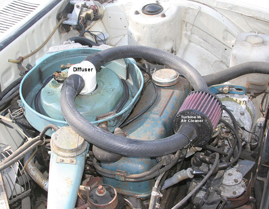 The vortex is created by cutting angled slots into a piece of PVC piping as shown here:  The air enters through each of six tapered slots cut parallel to the axis of the pipe. These give the air an initial spin inside the pipe and the pulsating intake of the engine, combined with the oval shape of the PVC exit T-piece, accelerates the air into a serious vortex which improves the intake to the engine, raising it’s efficiency and giving more engine power.  Ted created the egg-shaped part of the final PVC T-piece by adding an extra cut section of PVC pipe to a standard T-piece as shown here:  The turbine which Ted put on his bike works outstandingly well. The torque curve is extended well below it's former efficiency range. It is possible to substantially enrich the fuel / air ratio and still maintain the same mpg results as before. When the turbine is removed, both the mpg and the engine performance go way down. The turbine adds more air to the engine. To take full advantage of the possible increase in performance, the mixture should to be enriched. Ted also put one in his 1995 Toyota Corolla car which has an 1800 cc 4 cylinder engine and a 5 speed gearbox and he is getting over 40 mpg on the open road and the low 30s around town. Originally, those figures were 34 on the open road and 27 around town. The performance has also increased very noticeably. Another nice feature is the lack of knocking and pinging under load. Performance in the mountains at high altitude is also significantly improved. Ted has spent only a couple of months testing and evaluating this device on his cars and bike. A problem with this device is that it cannot be run directly through a carburettor, as it can with a fuel injection system. A carburettor works with a venturi which develops a low pressure zone in the throat with respect to the float bowl pressure. A vortex has no respect for a venturi and creates it's own pressure gradient which screws up the fuel metering. Ted has somewhat solved this issue by diffusing the vortex just before it enters the carburettor. Pressure and velocity are built up before the carb then sent through a diffuser. There is still plenty of research to do with this device. And there will be many improvements and beneficial modifications still to be made to it. Ted remarks that he does not have access to any engine test facilities and that makes it difficult for him to assess accurately the results of any design variations which he may make. Ted is hoping that someone will take his design and improve it further. There is great potential in this little piece of plastic pipe. Ted has fitted a different style of his turbine to his Toyota as shown here. The turbine section is marked “PMT” which stands for “Poor Man’s Turbo”, though obviously, you don’t need to be poor to benefit from a turbine system like this which has no moving parts:  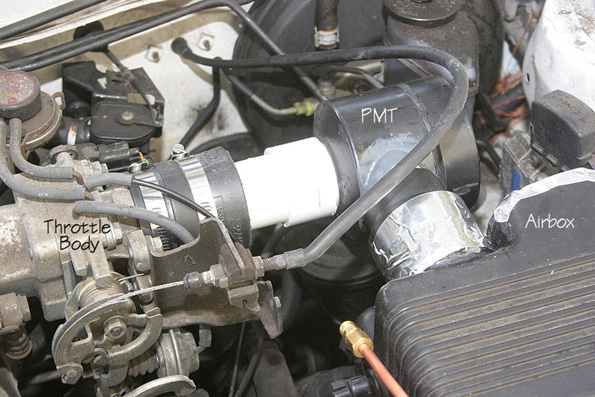 Cam Timing A deceptively simple way of improving mpg performance has been discussed recently in the watercar forums, and that is the adjustment of the cam settings on American cars made since 1971. This sounds most unlikely, but it is a proven fact. For example, a 2004 Jeep Wrangler 2.4 litre received a 10 degree advancement on both cams, and that gave a 70% improvement on the mpg, much more engine power and an exhaust which runs much cooler. Over the years, one man experienced a 50% to 100% improvement in mpg over a range of personally owned cars and trucks, and the emissions were improved by nearly 90%. It is not suggested that everybody should make a cam adjustment, just to be aware that an adjustment of that nature can have a dramatic effect. Another example: “Advancing the cam timing will make the engine run cooler. I have been messing with cam timing for about 25 years. I had a 1985 Ford Ranger with a 2.8 litre engine - it was a dog. The same engine used in the 1970 Mercury Capri had lots of power. The Ranger was a dog because the cam timing was set almost 10 degrees retarded. I gave it an 8 degree advance and the Ford Ranger came to life and hauled ass. Also, after-market ratio-rocker arms help a lot on late model cars. I changed the cam timing on my 1998 Chevy truck by 10 degrees. With it’s 350 cubic inch engine and ratio rocker arms installed, it gained almost 90 horsepower and brought the power band lower giving more torque because the rocker makes the cam have higher lift and longer duration on the cam which makes it breath better.” Comment from a man with 25 years experience in this field: “Cam timing is when the valves open and close in relation to the crank shaft and piston movement. The number 1 piston is set at true Top Dead Centre. At this point the degree wheel is set to the front of the engine against the front pulley at the zero degrees mark and you install a pointer mounted to the engine block pointing at the zero mark on the wheel. When the crank is turned to about the 108 to 112 degree mark, the intake valve is fully opened. That is where most engines are set nowadays. This what I call retarded cam timing. The engine seems to run well but doesn't really to seem to have much low and mid-range pulling power. When racing, you would retard a cam for high RPMs, they also could breath and had no restriction in the exhaust. The power may come in at, lets say, 3000 - 6500 RPM and advancing a cam for more torque and power, that same cam may produce power at 1000 - 4000 RPM and after all, who drives over 4000 rpm on the road?” Another comment: “Our jeep has twin overhead cams. Advancing them does not make them stay open longer, they just open and close sooner. My reason for advancing both cams was, if I only advance the intake cam, the intake would open earlier causing more overlap if the exhaust wasn't advanced. Normally the intake valve closes after Bottom Dead Centre. Just by looking at the piston, sometimes it's almost one quarter of the way up on the compressing stroke before the intake closes. By advancing the cams, the intake closes closer to BDC. This produces higher compression. Years ago, when I did this to some of the V8s, I would switch to adjustable rocker arms and a solid lifter cam. I was able to adjust the overlap by backing off on the rockers. On an engine with one cam, advancing the cam will adjust both the intake and the exhaust. Rule of thumb is: lets say most engines are retarded by 4 degrees or more, you really don't want to advance the cams more than 4 degrees advanced. I sometimes push this as far as 6 degrees advanced for improved mpg. That is a total difference of 10 degrees from 4 degrees retarded to 6 degrees advanced. This works well with low compression engines. I also don't see a need to go to a higher compression ratio. Think about it: if you had a compression ratio of 12 to 1 and the intake closes a quarter of the way up the compression stroke, how much is compression will there be, compared to a 8 to 1 compression ratio where the full stroke compresses the mixture? If you had a engine that made it easy to get to the cam or cams by just removing a dust cover, like on our Jeep 4-cylinder, I would say to install adjustable timing gears. Then you could just remove the cover and play with the cam timing until you came up with the best power and mileage. The FireStorm Spark Plug: The “FireStorm” plug was developed by Robert Krupa and it is an innocuous looking spark plug which can be used to replace a standard spark plug in an ordinary production engine: 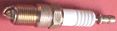 However, this plug is far from ordinary. The central electrode has been changed from a cylindrical post to a hemispherical dome, surrounded by four arched electrodes, each of which being positioned at a constant distance from the hemisphere. This allows a much greater spark area and results in very much improved performance. The fuel/air mixture can be made leaner without any harmful side effects. If this is done using standard plugs, then the engine will run at a much higher temperature which can damage the engine. But when using FireStorm plugs, a leaner fuel/air mix actually results in the engine running at a lower temperature. Robert has measured this effect and found that under identical running conditions, the engine exhaust was 100oF cooler when using FireStorm plugs. A mixture ratio of 24:1 is used rather than the current 14.7:1 mix and polluting emissions are very much reduced by the use of this plug design. Mixtures of up to 40:1 can be used with this plug. Robert has been awarded two patents for this plug design: US 5,936,332 on 10th August 1999 and US 6,060,822 on 9th May 2000. These show variations of the basic dual arch electrodes, two of which are shown here:  It was hoped that these plugs would go into production early in 2008 but there is no word of manufacturing starting. Robert gave Bosch of Germany a set of FireStorm plugs to test. After ten weeks of testing, their response was “This is unbelievable - we have never seen anything like this in all the time we have been building sparkplugs”. When standard spark plugs fire for a long time, the spark gap increases and the spark is weakened. Bosch ran an eight-week endurance test on the FireStorm plugs and found that there was zero gap growth. They concluded that FireStorm plugs would never wear out (which may well be why they are not yet in production - after all, who wants to manufacture something which never wears out?). Robert’s first FireStorm plug was made in 1996 and he has encountered strong opposition to their introduction and manufacture ever since. This plug will not be popular with the oil companies as less fuel is burnt. This is probably a fallacy because, human nature being what it is, people are likely to keep spending the same amount on fuel and just drive more. For the same reason, the plug will not be popular with governments who tax fuel. The companies who make spark plugs will not like it as it does not wear out like standard plugs do. It uses less fuel and cuts harmful emissions dramatically, so it will be popular with motorists and environmentalists, if Robert can get it into production. Plasma Ignition. If any form of construction work with a vehicle is beyond your abilities, then the plasma ignition system offered through this web site may be of interest to you. The company offers a system which can be used with any cheap non-resistor spark plugs and they claim a 40% improvement in mpg performance. 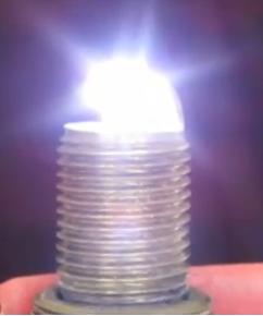 The video here explains the details of the system and claims that the resulting plasma from the plugs is so powerful that it can ignite cold water mist. Also, because of the very much improved fuel burn, the engine timing can be adjusted closer to the Top Dead Centre position, increasing the engine efficiency further. The very cheap spark plugs are liable to need replacing after five thousand miles or so, but that is hardly a serious overhead. The system can be used with 6-cylinder vehicles, 4-cylinder vehicles and electrical generators with one or two cylinders, and with outboard engines. Water Vapour Injector System: Fifty years ago car engines were not nearly as powerful as they are now. In those days it was quite common for a driver to remark that his car ran smoother and more powerfully on wet days. This was not imagination as water vapour drawn into the engine along with the air, turned to steam at the moment of ignition, and expanding provided additional thrust to the pistons while lowering the running temperature slightly. This fact was utilised in World War II when units which were effective standard bubblers used with hydroxy boosters were added to the vehicles. Roger Maynard has built and used these units extensively since 1978, and my thanks goes to him for providing this information and illustrations. 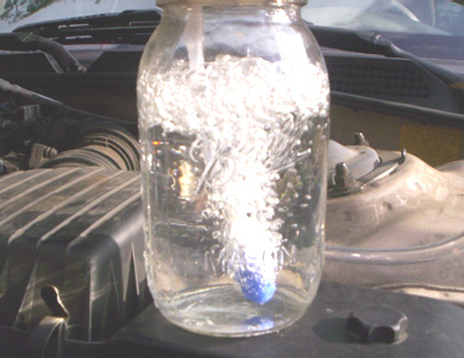 The unit is attached to the air intake of the vehicle, between the air filter and the engine. A small diameter plastic pipe is lead from there to a glass or plastic container holding water. In the above picture Roger is using a glass Mason jar with a screw-on metal lid which has a seal. Sometimes called a preserving jar, these jars are very convenient. The air feed into the jar is by a length of the same plastic piping and terminated with a standard air-stone or “soap-stone” as used in a home aquarium, as this causes a large number of separate bubbles. It is good practice to glue the plastic fittings to the lid of the jar, but this can make the jar too airtight and if that happens it may be necessary to remove the rubber seal which is around the neck of the jar. 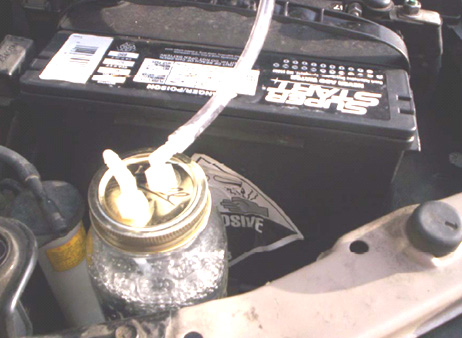 A glass jar has the advantage of not being affected by the heat produced by the engine. This is a very simple unit and it uses ordinary water which is not exactly a hazardous substance. The effect of using it is far greater than would be imagined. On Roger’s 4-cylinder KIA car, the mpg rose from 320 miles per tank full of fuel to 380 miles around town (18%) and 420 miles on the open road (31%) which is a very marked improvement. On his 6-cylinder Tacoma shows an 8% increase around town and a 12% increase on the open road. The water is topped up every 1200 miles or so. However, some engines are suited to the air-stone and some are not. Smaller engines may work much better if a stainless steel screw is used instead of the air-stone: 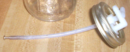 Just to clarify the operation of the device:  The container has a plastic elbow connection in the lid through which the outside air is drawn into the container. The air flows down through a plastic tube to either an air-stone from a pet shop, or a loose bolt in the end of the plastic tube. The air-stone has many small holes in it and these break the incoming air up into many streams of small bubbles. There is a second elbow in the lid and the air, which is now very damp, is drawn out through it by the reduced pressure in the normal air intake of the engine. The lower pressure there is caused by the intake strokes of the engine and the air going to the engine now comes from two sources – the normal path through the air filter, and the new path through the bubbler. Most of the air flows through the air filter as normal, but there is now a small percentage which flows through the water, adding cold moisture to the airflow. Some people feel that this couldn’t possibly make any difference, but experience has shown that the addition of this extra stream of damp air can and usually does have a beneficial effect, improving the mpg, making the engine run a little cooler and generally improving the operation of the engine. It is a very simple low-tech device which does not cost much, so if you feel inclined, then try it out and see what effect it has on your vehicle, after all, if it does not provide a useful improvement, then you can easily remove it. Fuelsavers: A similar system is on offer from the website where they offer small aluminium fins which mount on top of the trailing edge of the bodywork of a vehicle. The devices are reckoned to save some 10% to 12% on fuel consumption, they can be home-made, nine per vehicle is the recommended number. The device and mounting look like this: 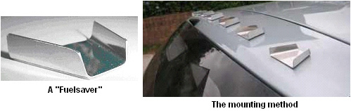 The Ram Implosion Wing: The next device may not be a “free-energy” device as such, but if not, it is very close to being such. It is a structure, which when mounted on top of a motor vehicle, improves the airflow to such an extent that the fuel consumption is said to be reduced by a major factor. The device was invented by Robert Patterson and is said to create a vortex which not only decreases wind resistance but may also create a forward propulsion force.  It is claimed that the effect created by one of these wings reduces the amount of dust stirred up when driving along a dirt road and if there is a paper bag sitting in the middle of the road, it is left unmoved when the vehicle passes over it at high speed. About a dozen people are testing this device at the present time. The biggest effect is at speeds of 60 mph or more. One researcher states that he installed the wing on the roof of his Lincoln Town car using a roof rack which allowed the wing to hang over the rear window by some six inches. He states that his fuel consumption has improved from 17 mpg to 56 mpg. Positioning of the wing, texturing of the wing surface, and the speed of the vehicle appear to be important factors in gaining an improvement. There is a research group and the website is at: www.pureenergysystems.com. High Mileage Carburettors. The very poor mpg figures produced by most US vehicles is a quite deliberate arrangement forced on drivers by the oil companies. In 1997, an engineer working at a US Ford company plant witnessed a 351 CID V8 started at about 4:30 pm. with a 1 litre bottle of fuel as an exactly measured amount. The next morning when he went to the factory floor, that engine was still running and had only consumed about one third of the one litre bottle. On asking about the fuel consumption, he was shown a display that read, "248.92 mpg". He was shocked and said, "This must be a mistake" but the engineer said that it was true. He then asked when they would have it ready to be put in a new Ford, he was told that he would not see it in his lifetime. This is company policy and has nothing to do with engineering which is easily capable of this level of performance. That 249 miles per US gallon is 298 miles per European gallon since the European gallon is 20% bigger than the US gallon. There have been more than 200 patents granted for high-mpg carburettors. These designs all give between 100 and 250 mpg on a US gallon of fuel. Not a single one of these designs has made it to the marketplace due to the fanatical opposition of the oil companies. Last year, the Shell oil company posted typical earnings for the year, which showed that that they had made US $3,000,000 profit per hour for every hour of every day of the entire year. Did you enjoy contributing to that profit every time you bought fuel to burn? Nearly all of these high-mpg carburettor designs convert the fuel to vapour form before it enters the engine. There is no magic about this performance, just good engineering practice. It will probably come as a great surprise to you that the oil companies now put additives into the gasoline sold in the USA. They have 103 varieties of additives and I expect that they will explain that these are used to reduce evaporation in summer (as if they care about that !) and combat freezing in the winter. An “unfortunate” side effect of these additives is that they clog up any carburettor which converts the fuel to vapour form. Instead of 200 mpg, it is now quite common for US vehicles to have a 15 mpg performance and that effectively increases the cost per mile by more than ten times. I am confident that it would be possible to design a high-mpg carburettor which deals with the additive sludge left over when the fuel is converted to vapour. In passing, the present situation gives added encouragement to stop burning oil-based products and switch to electric, compressed air, or water-powered vehicles. That is a perfectly viable option technically, but it would create frantic opposition from the oil companies and most governments which raise massive revenues from taxing oil products. The energy problem is not technical, it is financial and political. Bob Boyce in America was handed a 3.5 year jail term for “running a vehicle on an unapproved fuel”. Bob was testing a car engine on HHO in his workshop behind his house and not on the road. Bob beat the charge in court. Since then, Bob has been told by the US Military that it is ok for him to build and use HHO boosters but he must not run a car on water alone. Guess who gives the US Military orders. Guess who does not care about the American people. A book on building your own high-mpg carburettor written by Larry D. Wagner can be downloaded from here but please be aware that thirty years has elapsed since it was written and gasoline in the USA is liable to be contaminated by additives which were not used thirty years ago and so, some variations may be needed. Wagner remarks that Pogue said that the new additives prevented him getting the same high mpg figures that he used to get. In the Appendix, you will find eight out of the many high-mpg carburettor patents. The most famous of these are the three patents by Charles Pogue: www.free-energy-info.com/PatCarb1.pdf www.free-energy-info.com/PatCarb2.pdf www.free-energy-info.com/PatCarb3.pdf  It would never have occurred to me that a carburettor could be used for anything other than feeding an engine, but a very experienced and practical man who lives in Alaska has used them for other things. He says: I started out in 1976 when the first oil crunch came along and the Pogue system seemed to make the most sense at the time. We were looking to get a system started for making alcohol fuel and we were looking to develop a continuous-batch alcohol plant. This can produce feed for animals, fertilizer for the farms and fuel for vehicles or houses. It was based around growing barley and as barley is not good animal feed when grown, it needs to be cracked in some form and it was learned that this was a suitable method which had been used throughout Europe in ancient times. Two years later, the state passed a law banning alcohol fuel production. However, some of us wound up making heaters to use the alcohol produced in this way and those heaters were very efficient and they helped a lot of people, so something good did come of it anyway. It was about this time that I met a man who had done research on the Pogue carburettor for the Sun oil company in 1928. He was very knowledgeable and helpful and in his 80's at the time. He agreed that going to alcohol, would be a better idea as it would solve many of the problems which had been engineered into gasoline fuels. If you look at present day engines, they are as far as possible from what is needed for using this method. High compression engines will fire from heat generated under compression before top dead centre and will knock the top out of the pistons as it is an explosion rather than a burn. So, low compression engines are preferred, and firing at least 10 degrees after top dead centre. A long-stroke engine is best and some added flywheel weight increases the engine power. The incoming air needs to be pre-heated to reduce the amount of heat drawn from the combustion by the nitrogen in the air. It is the nitrogen heat content that suppresses the burn of any open fuel. the GEET system is very similar to what we did with a few exceptions. We heated a small amount of fuel using an electric element, converting the fuel to vapour, pressurising it using the exhaust which made controlling the amount of vapour much easier. All the rest is basic GEET or Pogue. There are many devices which I have made over the years, including the Pogue carburettor which can get very good energy efficiency from burning fuels. It is used by many industries from smelting furnaces to trains for transporting goods but it is not used by car manufacturers. I like to study industry, because they use what works in the real world, even if they refuse to share the knowledge with others. Our group built a few metal smelters for cleaning aluminium and casting ingots. They use waste oil and roar like mad, smelting 50 lb engines in 15 minutes or less, burning less than a pint (half a litre) of oil to do it. Allen Caggiano If you think that this is exaggeration, take the case of Allen Caggiano whose high-mileage carburettor constructional details are here.  Allen is an inventive and stubborn man not readily blackmailed or browbeaten. In 1978 he produced the design for his first high-mileage carburettor, assembled the prototype and installed it in a 1973 Dodge Coronet station wagon. This gave spectacular results of 111 miles per gallon. Unfortunately, it failed after a short time. In 1979, he installed the second generation device on a 318 cubic inch (5.2 litre) Dodge V-8 engine and called it the “FIVS Gen II” standing for “Fuel Implosion Vaporisation System Generation 2”. This second prototype proved very reliable and produced results as remarkable as the first, getting as much as 113 miles per US gallon (European gallons are 20% larger than US gallons so 113 miles per US gallon is 135 miles per European gallon). The installation of the ‘FIVS Gen II’ required modifications to the carburettor and the removal of the catalytic converter. This was prohibited by EPA regulations. It was therefore a violation of Federal Law. Al ignored the regulations because he knew tail pipe emissions from his FIVS vehicle were much lower than the law required. He was upholding the spirit of the law, and he was willing to argue his case in court if it came to that. He wanted a confrontation, he wanted a chance to tell the world that his FIVS made pollution control devices obsolete. He painted the station wagon bright yellow and in bold black letters along the sides he wrote: “This Car Gets Over 100 Miles Per Gallon and Doesn’t Pollute the Air”. On the third day of his new campaign, as Al got into the station wagon he noticed a car pulling up behind him. He got out to greet two men in suits flashing FBI credentials. While he spoke to one, the other slipped away, climbed in to his station wagon, and drove it off. Astonished, he turned to watch his vehicle going down the street. Then he heard the FBI car pulling out behind him. Al just stood there watching the two vehicles disappear around the corner. An old friend, his attorney, later called the FBI office. The FBI denied any knowledge of the incident. Angry and frustrated, but undaunted, Al said good-bye to the Dodge Coronet, and found another similar Dodge station wagon and set to work installing another FIVS system. He painted this one yellow, too, with bold black lettering. Not long after the first car was stolen, he received an interesting offer from a California based corporation. This corporation wanted to purchase exclusive rights to his FIVS Gen II. Al asked his attorney to check it out. The corporation turned out to be a subsidiary of several other corporations, all of which were owned by an oil company. This arrangement is typical of the way contemporary monopolies are structured. Al had been doing some reading about other inventors in the past and other fuel saving devices that had never seen the light of day and he was determined that he would never allow the oil companies get control of his device. After he refused the offer, two different FBI agents came calling. He was careful not to leave keys in his unattended vehicle this time. They informed him that he was violating Federal laws and should cease and desist. Defiant and excited that he might soon make his case in court, he told his wife, Deb, not to worry. A couple of weeks after the second FBI visit, unmarked brown paper envelopes began arriving, containing 8” x 10” photographs of the children and Deb. A child on the playground at school. A child getting off the school bus. Deb in the supermarket, and so on. She was terrified and the marriage broke up. The FBI was behaving like the Mafia. He wrote on the side of his Dodge: “The Big Boys Are Trying To Make Me And This Car Disappear! HELP ME!”. One his oldest friends, his attorney, who was like a brother, refused to have anything else to do with him: “Wake up!” his attorney said, and then abruptly hung up the phone. The Feds weren’t going to give him his day in court to defend his FIVS. They had stolen his first prototype vehicle and they knew it worked as claimed. He had refused to relinquish his control, so they were going to send him to prison, but not for violating federal emissions regulations. On the face of it, the Environmental Protection Agency appears to be imposing regulations on the auto makers and the oil companies in the public interest of protecting the quality of the air we breath, and the quality of the air we breath is improved over what it used to be. But in fact, these special interests often write the legislation themselves. The regulations then create a profitable new area of business which allows the special interests to increase their control over the market. The public interest is best served by creative innovation in a free market. Al was learning Politics 101 the hard way. In the business of vehicles and oil, there IS no free market. In a monopoly-controlled market, there are anti-competitive regulations, dirty tricks, and active suppression. The Big Boys protected their turf and took control of or destroyed any potential competition in the hallowed tradition of John D. Rockefeller Snr. and the Robber Barons of the past. That wasn’t hard to understand. But he was unprepared for the sophisticated tactics of today’s faceless Robber Barons. The Chief of Police for Brockton, planted stolen cocaine in Al’s home during a drug raid that ultimately put Al in prison in 1986, for 15 years on a cocaine trafficking conviction, in spite of the fact that Al didn’t use drugs, nor associate with those who did. He fought back. In prison, he fashioned a key in the prison shop and simply let himself out. He contacted a friend on the police force and then turned himself in on the same day. This police officer friend was able to uncover evidence of the chief’s corruption. Two days later, the Chief was arrested for stealing cocaine from the evidence locker, most of which he had taken home to feed his addicted wife. He went to prison himself, which led to the reversal of over 300 drug convictions that had been decided during his tenure. The Massachusetts Supreme Court of Appeals overturned Al’s conviction. For a moment, he thought he’d beaten the Big Boys and was a free man again. But then the Federal Prosecutor stepped in and indicted him on new charges relating to the seizure of two shot guns during the phoney drug bust. A spurious interpretation of the US Code was applied. Al was sentenced to a total of 30 years in Allenwood Federal Prison, without parole. Al’s time in Allenwood was not wasted in self-pity or bitterness towards the Big Boys or the corrupted system that put him there. He was popular in Allenwood right away because of his role in exposing the dirty cop that overturned so many drug convictions. He developed a good relationship with the warden of facilities. As a licensed HVAC contractor, Al was able to fix the prison heating and cooling system that had never worked properly, saving the government a large amount of money. Honeywell Corporation trained him in the use of computers so that he could operate and maintain the system. The prison had an excellent machine shop which allowed him to continue working with his FIVS devices. He designed small FIVS for the prison lawn mowers and produced numerous FIVS GEN II’s, with the collaboration of the warden of facilities, that were secretly distributed outside. Al made many useful contacts, one of whom helped him secure US Patent 5,782,225, awarded July 21, 1998, for the FIVS Gen II. He designed a new FIVS, the “Gen III”, which did not violate any Federal regulations, and he put together a plan to manufacture and distribute the Gen III. And then one day he was out, free for real in 1997. Sentenced to 30 years without parole, he was suddenly released after ten years with five years parole. The Federal appeals court had finally ruled that his possession of two shotguns was legal and that it had no jurisdiction over the matter in the first place. Several years later, because he was curious, he asked a police officer friend to do a background check on him. No record of his conviction and incarceration in Allenwood was found. The stain of systemic corruption had been discretely removed. He didn’t look back and went to work to develop a prototype Gen III device, applied for his new patent, and implement the strategy he had dreamed up in prison. He was no longer politically naive, no longer the blindly patriotic American he’d once been. He did not believe it would be possible to build the Gen III in the home of the brave and the land of the free, so he made arrangements to manufacture parts in the Ukraine, a former satellite of the defunct Soviet Union. He would then assemble the devices in Mexico. He had developed a global perspective in Allenwood. His network of supporters and investors was now called: “FIVS Gen III International” and he set up a website which was generating 70,000 hits a month from all over the world. He also offered the complete blue prints for manufacturing the earlier FIVS Gen II as a free download from his site so that anyone who wanted to could build their own. He thought this might distract the Feds and tie up their manpower as he implemented the Gen III strategy. By 2002, the delivery date for the first beta testing group was set. The parts were shipped from the Ukraine to Mexico where they were assembled. It was necessary for Al to travel South of the border to oversee the operation. He made the punishing drive from Massachusetts to Mexico several times in his FIVS equipped Pontiac Catalina and it functioned flawlessly, delivering more than 70 mpg with its 400 cubic inch engine. His friends warned him not to drive alone, but he made the last trip by himself and on the return leg of the journey, he noticed an 18-wheel truck following him. The intentions of this truck were soon obvious when it overtook him and forced him off the road. Al anticipated the manoeuvre, however, and was able keep control of the Pontiac. He breathed a sigh of relief and continued on, believing he’d outwitted them once again. He made it all the way to Massachusetts and was nearly home again before the truck found him a second time and caught him unawares. The Pontiac rolled over several times, but landed upright. The driver’s side door was crushed and the roof caved in, but the car still ran and Al was able to drive it home without further incident in spite of his injuries. He had to be cut out of the car with a torch. He had several broken ribs and a punctured lung and was immediately rushed to hospital. The Gen III’s for the first group of licensees were shipped from Mexico on time, however, by means of several different shippers. Some devices for US licensees were shipped via United Parcel Service. A total of 137 units were shipped around the world. Only those that went UPS in the continental US and Canada, a total of 44 units, did not arrive at their destinations. Every shipped item has a tracking number, of course, and when Al inquired about the missing 44 units and provided the tracking numbers he’d been given, he was informed the numbers he had did not exist. The attempt to turn him into road kill was not completely unexpected, but Al was shaken just the same. He maintained his bravado, however, while friends and sympathisers reacted more predictably. When the intent of the suppression escalated from malicious to deadly, most began to slip quietly away and it was ‘High Noon’ again. Another complicating and aggravating factor was the appearance of a discussion group at the Yahoo website called “Get 113to138mpgNOT”. This Yahoo Group was established by an individual calling himself “David Rodale”. He was not a Gen III licensee. He (or she) was a freelance public servant dedicated to helping those who had been ripped off by the promoter of impossibilities, the unscrupulous scoundrel, Allen Caggiano. He provided advice and counsel to those disappointed licensees who had not received their Gen III devices. He assured them that they could find justice in the courts. Al spent much time and energy fighting back against this defamation. Al was fully recovered from his “accident” by this time and had repaired the Pontiac. He was feeling every day of his 59 years, but he soldiered on with a grim determination towards whatever final confrontation awaited him. When a careful, bloodless voice on the phone proposed a compromise one day, he felt ready to bargain. His website was experiencing growing traffic. T he voice told him that if he would just remove the Gen III from his site he would be left alone. It felt like a small victory, but he didn’t relish the idea of backing down. If Gary Cooper had received such an offer in High Noon, he would have taken it. He knew a bargain with the devil could never work in his favour, but he had to catch his breath, so he played along and removed the Gen III from his web site. It was a strategic retreat. If they would leave him alone, the beta testing of units already out there could go forward. The program was smaller than he had originally intended, but it was a start and if he could relax and gather his data, then he might ultimately win the game. However, a careful examination of the FIVS in his Pontiac one afternoon made his heart jump into his throat. He found a tiny hairline crack in the aluminium/titanium alloy canister. This Gen III unit had many thousands of miles on it. It presaged a potential disaster and he immediately notified all the licensees of the problem and recalled the units. He worked feverishly and discovered that he didn’t have to redesign the canister. A simple alteration appeared to be the solution. Al was then told that he required immediate surgical treatment. After the fact, this prognosis was shown to be false. While the surgery was underway, Al suffered a stroke. His heart stopped and he was technically dead on the operating table. In addition, the surgeon had damaged nerves in his spinal column. It was not his time to go, however, and he revived, but then lay in a coma for 30 days. When he finally came around in his hospital room, feeling more dead than alive, he was astonished to discover that he could not move his legs. It is possible, that Al's medical experience was not accidental. On the local TV noon news on a sunny day in the spring of 2003 he watched a dramatic live report of a SWAT team in action. They were closing in around a familiar looking building. He thought to himself: “Hey! That’s looks like my condo! Hey! That IS my condo!”. He watched the police seizing his yellow Pontiac in the parking lot as the Channel 7 reporter explained that Chelmsford, Massachusetts, resident, Allen Caggiano, had defrauded investors in a fuel saver scam and then fled the country. He didn’t see how that could be true since he was in the Intensive Care ward of the local hospital, not 20 miles away. Meanwhile “David Rodale” at Yahoo Group “Get 113to138mpgNOT” had found 20 disappointed Gen III licensees and was patiently building consensus for legal action at the state level in Massachusetts. It wasn’t easy to turn disappointment into outrage and a desire for revenge. In spite of the resources available to the Big Boys, they hadn’t been able to otherwise identify most of the testing program licensees. Al returned home to his condo to find his Pontiac with the repaired Gen III’s in the trunk gone from its parking space. His premises had been ransacked, his computer hard drives removed. With his mind foggy from pain killers, Al tried to concentrate on getting used to a wheelchair. Nurses from the Visiting Nurses Association were with him around the clock. Gradually he stopped using the pain killers. He began to notice sensation returning to his legs. Even as he felt himself improving, his diabetic condition inexplicably worsened. Twice he was rushed to the hospital in a comatose state. The third time this happened, a nurse checked his pill box and discovered insulin pills that should not have been there. He was now taking insulin through injection, but the old insulin pills were still in the medicine cabinet and had been put in his pill box with his other medications. The result was insulin shock. The nurse, Michele, who had done this, not once, but three times, did not again appear for her shift. Al tried to reach her to ask for an apology for her mistakes, but she had vanished. The Visiting Nurses Association denied having any record of her employment. “David Rodale” was having success convincing the disappointed licensees to file suit, and with the newly acquired information about the FIVS Gen III International operations taken during the SWAT assault, a postal inspector launched a preliminary inquiry into the feasibility of action at the federal level for mail fraud. Rodale was confidant that the threat to society posed by Allen Caggiano was now neutralised. He announced to the Yahoo Group members that he’d done his best and there was nothing more to do. He would leave the Yahoo Group in place for a while, but he planned to take it down in a couple of months. He was sorry that so many people had been taken in, and he hoped they’d be less gullible in the future. He was glad he could help. That summer, the judge dismissed the charges against Al in the Massachusetts court. His lawyer petitioned for the return of his property, the Pontiac the local police had seized a year earlier. He was told it had been taken to Washington, DC, and was being examined to determine if it violated any Federal regulations. A grand jury in DC was convened to investigate the Federal charges of mail fraud, but it failed to return an indictment. The licensees who had paid their money and signed their licensing agreements had agreed to assume the risks of a testing program and most of them did understand that part of the risk involved the historical efforts of the oil/auto cartel to suppress new technology that could affect their profitability or control over the markets which they ruthlessly dominate. Through his attorney, Al received an offer for exclusive rights to the Gen III. The amount of money involved beggars belief, and suffice it to say that Al again refused, as he had done in the early 80's when an offer was made for the Gen II device. The Big Boys have never attempted to prosecute him for the violation of Federal Emission Control regulations. He is clearly guilty on this score so far as the Gen II is concerned. To do so would result in the exposure of the fraud they are perpetrating on the public. Their technology is obsolete. As Al has pointed out on his website, they do not want a reduction in the demand for oil. This would mean a reduction in oil company profits. If the consumer used half or less of the oil now being used, government tax revenues would be reduced accordingly. If the Gen III were to become available the public interest in fuel economy and clean air would be served and Allen Caggiano would become rich beyond wild imaginings, but the oil/energy cartel and its partner in government would suffer. Therefore, the Big Boys will continue to do all that they can to stop Al and his FIVS and to keep the public ignorant of any technology they do not themselves control. If they don’t control it, and if you don’t buy it from them, then it doesn’t work, or it’s a fraud. The “FIVS Gen III International” enterprise has been successfully suppressed. Al’s fight to manufacture and distribute his invention and enjoy the great wealth it would have given him is over. The Big Boys have broken his bank, and his health. The struggle has nearly destroyed him. The money would have been nice, but it never was the money that kept him going. He is now donating his work of a life time to the American people. The Big Boys can harass, intimidate, and attempt to kill one man and his American Dream, but can they do the same to many thousands of Americans and others around the world? Al now gives away his “FIVS Gen III” plans free. Al will allow his patent application for the Gen III to expire. He can no longer afford the large investment required for a patent here and in other countries. His main concern now is to prevent the FIVS from being patented by anyone and to keep the device “open source”, so to speak, so that it cannot come under the control of the Big Boys and will remain freely available to the public. Though Al will not profit from his invention through licensing fees or royalties, there is considerable satisfaction for him in knowing that the Big Boys have not and will not ultimately win this game and destroy the work of a lifetime. reference site and forum and patent. Fuel Vapouriser Bubbler There is one technique shown here and reproduced by kind permission, which appears to be effective in spite of the additives. The method is very much like the technique used by Roger Maynard for adding moisture to the incoming air as described above. The difference is that instead of using water in the container, petrol is used. Improved performance of up to 60% has been achieved and experiments are continuing. The general arrangement is like this:  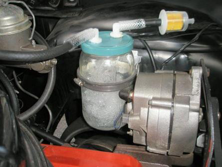 You will notice that the fuel level inside the container is kept fairly low in order to allow considerable space to contain the bubbles, allowing them to pop and not be drawn into the air tube which feed the engine. Vortex Fuel Reforming This is a very important technology which has been around for more than a hundred years. The objective is to increase mpg not just by the vaporisation of the fuel but also by "cracking" the water / fuel mixture into smaller molecules before being fed into the engine. This is more advanced than the fuel ‘conversion-to-vapour’ technique of the high-mpg carburettors. To get a better understanding of this, you can try a Google search for "fuel reformer" or "steam reforming" which will provide additional information which may help you to understand the basic principles. The fuel-reforming method can be highly effective and its effectiveness has been proven beyond all doubt with designs from MIT, Philips Petroleum, Nissan Motors, NASA, universities and other very serious contributors. Some years ago Cal-Tech spent millions proving that on board fuel reformers would give us all better fuel economy and cleaner air. They did long-term testing on buses and cars to provide proof. They teamed up with the very large auto-parts supplier Arvin Meritor to put them in production vehicles. Then "One Equity Partners" bought out Arvin Meritor's division that did all the final work to get fuel reformers in all our vehicles. They created a new company, EMCON Technologies, and that company dropped the fuel reformer from their product line, not because it did not work but because it did work. There are various techniques for achieving this process. One which is easy to understand is shown here:  Here, the standard exhaust pipe is given a kink to move it clear of its normal run in order to allow an extra straight pipe of smaller diameter to be positioned inside it so that the hot exhaust gases are used to heat the incoming fuel flow. This is a useful energy gain as it uses some of the waste heat, raising the overall efficiency of the engine very considerably. This extra fuel-flow pipe has a solid magnetised ferromagnetic metal rod mounted inside it, blocking off most of the pipe area. This change in available flow area causes the fuel flow inside the pipe to speed up, and as well as that, it causes the flow to spiral around the rod in a vortex flow:  However, the magnetism of the solid rod, causes a most unusual effect and instead of the helical gas flow being as shown above, a highly uneven flow pattern is created. This causes the fuel flow to bunch up in the centre of the tube, generating a hot spot which creates quite unexpected results:  The really incredible result of this peculiar effect is that the fuel mix exiting from the tube, contains chemical components which did not enter the tube - impossible according to present day physics. This goes to demonstrate once again, that we really don’t yet understand the world in which we live. The fuel mix for use in this system is best provided by two tiny carburettors, one feeding a fine mist of water droplets and the other a fine mist of fuel droplets. These are fed directly into the intake of the fuel reformatter tube. These carburettors are of the miniature type used for radio control model aircraft and their venturi intakes are blanked off with a plate with a small hole in it. Air is not fed into the reforming tube – after all, this is a fuel reforming system. The air is mixed in with the reformatted fuel after it exits from the reformatter, as shown below. Some of the hot exhaust gas is fed into both of the carburettors in order to help prepare the mixture for the reformatting process. The blanking plates on the carburettors are there in order to reduce the amount of the exhaust gas being drawn in with the fuel:  The use of carburettors is important since using a bubbler as suggested in the free plans on the internet, creates problems as the lighter fractions of the fuel get taken first which is exactly what we don’t want to happen. The carburettors have the massive advantage that they feed all fractions of the fuel together and so the remaining fuel is always in the correct proportions. The ratio of water to fuel (typically gasoline or diesel) can be adjusted over a very wide range, with some people using 90% water. Actually, there have been claims of running on 100% water, using multiple reactors in parallel with energy being drawn either from transmutation of elements or perhaps spin interactions with the local environment. Jean Chambrin's patent give details of running only on water. There are several forums where members are researching and using various designs of fuel reformers, with the GEET designs being popular. The VortexHeatExchanger forum is one such research forum and one of the files there lists 214 different patents for these devices. There are several different types of reformer. Another forum is the GEET-Pantone forum.. Almost any hydrocarbon fuel can be used - vegetable oil, old motor oil, etc. the normal fuels are the most popular. A forum member named ‘bryishere’ says in a YouTube video comment: "Everyone should really try this. IT WORKS. I have spent a lot of time on this device. It's very simple. Just follow the plans and experiment as much as you can. Currently I am using 90% water and 10% crude oil/waste oil on a 1-ton, 1969 Chevy truck ....... Get out in your shop !!!!!" Video information on reforming can be found here and these devices are often used on stationary generators. These devices have been popular in France for some years now. Jean Chambrin found that the gases needed to swirl inside his reactor in the same direction that the crank was turning. There is a massive 175 Mb file called ‘FuelReformerTechnology.zip’ which you can search for and download from the internet if you are very enthusiastic. That file contains the contents of more than 220 patents and applications. These patents are also listed in the ‘Files’ section of the Yahoo VortexHeatExchanger forum mentioned above. The Weird Nature of Water This chapter has been dealing with systems for enhancing vehicle operation with the use of water, so it seems appropriate to finish it with a brief note on water itself. To a casual glance, it appears that we know all about water. It’s composition is H2O and when it breaks down, we get two hydrogen atoms and one oxygen atom - right? Well maybe, and maybe not. The longer you spend looking at systems which use water, the more you get to realise that water is by no means as simple as you might initially think. There is a much maligned branch of alternative medicine called “Homeopathy” which is based on giving patients very dilute water-based solutions various chemicals. Sceptical investigators have run professional-quality tests intended to show that homeopathy is fraudulent and has no medical benefits whatsoever. Unfortunately, the tests did not work out the way that the investigators wanted. The tests showed that there actually was some benefit from the treatments being examined, and unfortunately, because a placebo control group was being used, the placebo effect was definitely not the cause of the effects recorded during the trials. Determined not to just accept the results which went against their expectations, the testers started testing ever more dilute samples on the patients. They eventually got down to the level where there no longer remained a single atom of the chemical in the liquid being fed to the patients, but to their consternation, the medical effect remained. They tried water which had never had the chemical in it, and there was no medical effect. They returned to the apparently “pure” and definitely chemical-free water and the medical effect was seen again, in spite of the fact that there was not even one atom of the chemical remaining in the water. This showed clearly that the water was different after having had the chemical in it, even when no chemical remained. They were forced into the opinion that water has “memory”. That, of course, is a conclusion based on the facts which are hard to explain. You may wish to deduce something else from those facts, and that is entirely up to you - just be aware of the facts. Very interesting studies carried out by Mr Masaru Emoto here have shown that the thoughts of ordinary members of the public can alter the structure of water without there being any actual physical contact with the water. If the water receives positive thoughts and is then frozen, the resulting crystal structure will be like this:  While on the other hand, if negative thoughts are aimed at the water, whether just by looking at it and thinking, or by writing those thoughts down on paper, the resulting crystal shape is quite different when the water is frozen, as shown here:  It is not all that startling if you consider that the quantum mechanics researchers have been saying for a long time that experiments can be affected by the observer. People who build Joe Cells which operate through environmental energy focused by specially treated and structured pure water, record the fact that certain people can affect a Joe Cell in a negative way from a distance of fifty yards (or metres) away. Personally, I am quite sure that we do not understand the fundamental nature of our environment and that we have very little idea of how we as individuals impact on our surroundings. There is an extremely honest and reputable researcher called George Wiseman who operates through his company Eagle-Research (website). George is very experienced in producing “Brown’s Gas” and he publishes excellent instruction books on the subject. The really interesting thing is that Brown’s Gas is produced from water and that gas has the most remarkable properties which are not readily explained by our present day “conventional” science. When Brown’s Gas is used as the gas to power a cutting torch (like an oxy-acetylene torch) the resulting flame is nearly colourless and can be waved across a bare hand without any ill effects - the hand is not burnt. But when applied to a fire brick which is intended to resist high temperatures, it burns a neat hole through it. It will vaporise a tungsten rod which normally takes 6,000oC to do that, which indicates that the flame temperature depends on what it touches (!). It can also weld aluminium to aluminium without the need for an inert gas. It will weld aluminium to brass and it can weld a steel rod to an ordinary building brick. It can fuse glass to a building brick. This is not “normal” for a chemical combustion reaction, showing that Brown’s Gas is not a “normal” chemical substance. As Brown’s Gas comes from water, does that perhaps suggest that water is not a “normal” chemical substance? I will leave you to make up your own mind about that, perhaps helped by the following, most enlightening presentation by Moray B. King.  Moray King has produced a substantial document covering many aspects of free-energy with special emphasis on the more unusual systems and some of the difficult-to-explain things which people have discovered. As Moray’s presentation has 166 pages containing many pointers to video clips and specialist web sites, this is just a brief summary of his pdf document which can be seen in full here and which has the uncommon feature of an icon at the top left hand corner of each page, and if you click on that icon, then additional comments can be seen. He starts with:
Steve Ryan, a man living in Auckland, New Zealand, who was shown running a motorcycle on modified water, shown on a cynical TV video presentation here where the complete ignorance of the presenters is  demonstrated yet again. Steve has disappeared from public view for a very long time now. However, Moray raises the most relevant question: “How can water store enough energy to make it appear to be a fuel?” The first step in answering this question is to realise that causing cavitation (tiny stress bubbles) in the water inside an electrolyser, produces excess energy, and so, circulating the water inside an electrolyser while causing cavitation in the water is a major step forward, and one which seems to indicate that the majority of the energy in HHO gas does not actually come from the hydrogen. Instead, zero-point energy gets trapped in the water when the turbulence caused by the circulation, charges the water electrostatically, raising it’s energy content as it circulates repeatedly through the electrolyser. demonstrated yet again. Steve has disappeared from public view for a very long time now. However, Moray raises the most relevant question: “How can water store enough energy to make it appear to be a fuel?” The first step in answering this question is to realise that causing cavitation (tiny stress bubbles) in the water inside an electrolyser, produces excess energy, and so, circulating the water inside an electrolyser while causing cavitation in the water is a major step forward, and one which seems to indicate that the majority of the energy in HHO gas does not actually come from the hydrogen. Instead, zero-point energy gets trapped in the water when the turbulence caused by the circulation, charges the water electrostatically, raising it’s energy content as it circulates repeatedly through the electrolyser.
Mark LeClair, the founder of the NanoSpire Corporation (nanospireinc.com), discovered a microscopic crystalline form of water which has an extraordinary energy density. This crystalline form of water is similar to the microscopic plasmoids discovered by Ken Shoulders and the larger plasmoids discovered by Adamenko’s team at the proton-21 laboratory in the Ukraine. When a plasmoid strikes any element, the result is transmutation of that element. The excessive energy and most unusual properties of Brown’s Gas come from charged water gas clusters which are stored in a stable ring-form of the microscopic water crystals. This feature completely by-passes the standard electrolysis of water as examined by the great Michael Faraday  where more energy is needed to split water than can be regained when the resulting gas mixture is burned. This is an entirely different process as explained here in considerable detail on Sterling Allan’s PESWiki web site, and it shows why water can indeed act as a fuel. If you search for “water fuel” on YouTube, more than 41,000 videos can be found, most of which are demonstrating electrolysers, which shows that there is a growing awareness of the potential of water as a fuel. There are many commercial electrolysers available. where more energy is needed to split water than can be regained when the resulting gas mixture is burned. This is an entirely different process as explained here in considerable detail on Sterling Allan’s PESWiki web site, and it shows why water can indeed act as a fuel. If you search for “water fuel” on YouTube, more than 41,000 videos can be found, most of which are demonstrating electrolysers, which shows that there is a growing awareness of the potential of water as a fuel. There are many commercial electrolysers available.
 Brown’s Gas (HHO) has most unusual properties as demonstrated by Denny Klein’s use of it in a welding torch as seen here and Denny has also run his car with water appearing to be the only fuel – the power comes from the zero-point energy field but that energy is transported by the water. Surprisingly, nearly everyone who is working with, or experimenting on the gas produced by electrolysis, believes that the resulting energy comes from the hydrogen in the gas mix, while the reality is that this is not actually the case. Brown’s Gas has a cool flame of just 130 degrees Fahrenheit (water boils at 212 degrees Fahrenheit), and yet that same flame can vaporise tungsten which requires more than 10,000 degrees Fahrenheit and burning Hydrogen will never, ever, reach that temperature. Brown’s Gas can also dramatically reduce radioactivity in radioactive materials and burning hydrogen can’t do that. Also, when Brown’s Gas is analysed in a high-tech laboratory, very little hydrogen is found and instead there are gaseous water clusters with excess electrons.
These charged water gas clusters have the same strange energetic effects that the plasma-charged have and that appears to be a microscopic form of ball lightning, studied extensively by Ken Shoulders who named them “Exotic Vacuum Objects” or “EVO” when he became convinced that their excess energy was being drawn in from the zero-point energy field of ‘the vacuum’. These water gas clusters have a self-organised grouping of matter, plasma and zero-point energy. The typical grouping caused by this turbulent plasma is a vortex ring called a plasmoid (which has often been proposed as a model for ball lightning):  In a plasmoid, the electrons and ions spiral around the vortex ring and the force-free vortex creates a natural stability which sustains the plasmoid shape. These charge clusters can be produced quite easily as shown by Ken Shoulders in his US Patent 5,018,180 of 1991 where he shows that an abrupt electric discharge from a capacitor through a sharp pointed electrode on to a dielectric surface creates a charge cluster which travels on the surface of the dielectric to the anode. It appears to be a micron-sized form of ball lightning and it can punch a hole through the ‘witness’ plate, leaving a crater made by a high-energy event. The patent is well written and describes many possible applications of his discovery.  The Exotic Vacuum Object formed by this process is believed to contain 100,000,000,000 electrons plus some 100,000 ions, giving it a charge-to-mass ratio similar to an electron and a really interesting fact is that it contains more energy than the energy which was stored in the capacitor which created it. These charge clusters adhere to dielectrics and they can remain for a long time. Many of them can clump together into a formation like a necklace. They can create holes through high melting-point ceramics such as aluminium oxide. Ken believes that the creation of these holes in ceramics is caused by the disruption of the electrons in the ceramic and so the hole ‘melted’ through the ceramic is not actually produced by heat. He has performed experiments which demonstrate the transmutation of one element into another and others which show radioactive materials being converted into benign elements. Water gas clusters have the same characteristics as Ken’s Exotic Vacuum Objects and they cause the most unexpected effects of using Brown’s Gas where the cool flame (266 degrees F) does not boil water (which needs 212 degrees F to boil) www.watertorch.com, and yet, that same flame can vaporise Tungsten which requires 10,031 degrees F, mind you, the Brown’s Gas flame does not vaporise Tungsten by heating it above 10,000 degrees Fahrenheit but instead, does it by disrupting the bonding of the molecules in the metal. Here are some comparisons:  This heating can’t possibly come from burning hydrogen. Some tests produce interesting results. For example, fill a balloon with the gas produced by electrolysis and leave the balloon sealed for some time. The tiny hydrogen atoms and molecules can, and do, escape through the material of the balloon, causing it to fall to the ground. But, the contents remaining in the balloon still produces a burning flame when pushed out through a small tube and lit. A similar experiment is to fill a paper bag with the gas. Seal the bag and leave it for twelve hours to allow the hydrogen to escape. What remains in the bag is a gas which is heavier than air and which can be ignited. George Wiseman (www.eagle-research.com) is a leading Brown’s Gas researcher who has found that browns Gas burns downwards in an imploding ring. In 2008, Chris Eckman measured the characteristics of Brown’s Gas at Idaho State University. The measurements showed that there was very little hydrogen (monatomic or diatomic) present. Instead, the gas was found to be a form of water with excess electrons, effectively, a gas which was neither water vapour nor steam. When ignited, the flame temperature was found to be 266 F. or 130 C. (Extraordinary Technology, vol 2(6), pp 15-25, 2008). When using his acrylic electrolysers, George Wiseman has made an observation which he says is never mentioned in any textbook describing electrolysis:  Between the electrolysis electrode plates which have a wide spacing of more than 10 mm, three sets of bubbles are produced. Hydrogen is produced on the negative electrode plate. Oxygen is produced on the Positive electrode plate. But, in the middle of the gap between those electrode plates a third set of bubbles are generated. Many researchers believe that these additional bubbles form the most energetic component of the gas – the charged water gas clusters. Bob Boyce has made a similar observation, noting that when electrolysis first starts, there are two jets which start from the plates and collide in between the plates where the middle bubbles are formed.    Ted Suartt and Rob Gourley (www.wateriontechnologies.com) have not only made the same observation, but have developed a process and applied for a patent where they intentionally harvest just the middle set of bubbles:
 Suartt and Gourley realised that the dominant electrolyser gas was not Hydrogen, and claiming that they are the first to discover this, named the gas after themselves as “SG Gas”. Their extraction process involves widely separated electrode plates and a method of extracting the gas bubbles produced in the middle region between those two plates and excluding the hydrogen and the oxygen produced. They have investigated the properties of water infused with the gas and claim that it has health benefits. They state that Rhodes Gas and Brown’s Gas are both “dirty cocktails” which include H2 or O2. The anomalies of Brown’s Gas are similar to those of plasma charge clusters (Ken Shoulders’ EVOs). It adheres to matter and is electrically polarised. It gives an electric shock if it implodes to form water again. The isolated gas tends to implode instead of explode in piston experiments. However, if air is added to the mixture, the air is heated and that can cause overall expansion. In a welding torch it has a cool flame but it can vaporise tungsten. The flame cuts cleanly through solid, high melting-point materials including wood and ceramics, can weld dissimilar metals together and can even weld steel to clay brick. The claims of neutralising radioactive materials as well as the transmutation of elements are extraordinary. Todd Knudston comments on these properties at www.amasci.com. At the 2011 Tesla Conference, Vernon Roth announced that he has observed element transmutation in his electrolysis cell. Details of this are given on Sterling Allan’s web page at peswiki.com. Mark LeClair can explain how water cavitation creates microscopic craters in metallic surfaces, carves trenches in high melting-point ceramics, transmutes elements, and produces excess energy. Cavitation bubbles have been studied and they have been shown to produce unexpected excess energy. Sonoluminescence occurs when water mixed with an inert gas such as argon or xenon, is excited by ultrasonic waves. A blue light is emitted as each bubble collapses suddenly and symmetrically. If that blue light were produced by a heating effect, then the bluish spectrum would indicate temperatures of over 10,000 degrees Kelvin, which caused many scientists to suggest that it might be used for hot fusion. Nobel laureate, Julian Schwinger, suggested instead that the light is caused by the zero-point energy. Here, the abrupt scalar compression of the bubble walls activates a Zero-Point Energy coherence, emitting the blue light at a far lower temperature (wikipedia). Mark LeClair has four patents on controlled cavitation (typically for the precision cutting of materials): US 6,932,914, US 6,960,307, US 7,297,288 and US 7,517,430.   Cavitation bubbles form in the low-pressure region behind any rapidly moving surface in water. Ship’s screws are notorious for making cavitation bubbles and being damaged by them:  However, the most useful application of cavitation is inside an electrolyser. Archie Blue raised the effectiveness of his electrolyser by blowing air upwards through the electrolyte. The technique can be applied to many different electrolyser designs. The electrode plates should have a rough clean surface with a tiny inter-plate gap of less than one millimetre. A gap that small allows the electrolysis gas to cause cavitation. The electrical stimulation can use pulsed DC waveforms but with minimal current and electrolyte (remember that we are not trying to make hydrogen). Circulating the water rapidly can charge it electrostatically and possibly even enough to allow the removal of the external DC pulsing. There are many ways to produce cavitation in water: make electrolysis gas in narrow gaps, blow air through the electrolyser, create a Venturi vacuum, vibrate the water by mechanical, acoustical or ultrasonic means, oscillate an electric field via a toroidal coil or via pulsed waveforms. Here, charged or polarised clusters or bubbles will oscillate with the field causing turbulence and cavitation. When a cavitation bubble collapses near a hole or irregularity, it forms a torus and all of the energy of the collapsing bubble gets concentrated into a re-entrant jet. The extreme pressure in the jet creates a new solid-state of water, a water crystal with a plasma bow shock wave which draws in Zero-Point Energy. If they collide, water crystals can form small rings, trapping the energy in a meta-stable torus form. This is the seed of the charge water gas cluster. When ignited, the ring breaks to re-launch the LeClair effect water crystal or alternatively, becomes a plasmoid Exotic Vacuum Object, either of which have excess energy. Rapidly circulating water through an electrolyser causes numeric energetic effects. It charges the water by electrostatic rubbing, it causes turbulence and cavitation as it flows through the tight rough gaps, it can vibrate the plates producing reed cavitation and best of all, cycling the water repeatedly through the electrolyser integrates it’s energy content, producing an ever increasing energy level. With water which is sufficiently charged, spraying it as a mist into the carburettor of an engine can give the illusion that water is a fuel. This is just a brief summary of part of the contents of Moray King’s presentation pdf document which you can read in full here: www.free-energy-info.com/MorayKing.pdf. An interesting, seemingly directly related video is: http://www.youtube.com/watch?v=i-T7tCMUDXU&feature=youtu.be. Considering what Moray King has described, we need to consider more carefully the patented electrolyser designs of Charles Garrett and Archie Blue. First, however, having discovered and considered charged water clusters we need to consider the patent application of 2010 from Ted and Rob: Ted Suratt and Robinson Gourley Ted Suratt and Robinson Gourley have developed a new gas and have done very wide ranging and extensive testing with some of those tests extending over a period of two years. They describe a gas derived from water which they call SG gas (presumably from Suratt/Gourley) and that gas has remarkable properties, being capable of dissolving in liquids such as water and various fuels. It can also soak into and enhance solids such as wood chips. It can be used as a fuel but when burnt it only reaches a temperature less than 300 degrees Fahrenheight but has remarkable properties including the melting of metals with far higher melting points. That challenges present day concepts of what “melting” actually means. The gas can be compressed to 1000 pounds per square inch an it maintains its properties long term even when compressed. Very, very little power is needed to produce the gas, so their work looks like a step forwards towards a new technology. In my opinion, the infused water produced by this process is likely to be what was used by Steve Ryan of New Zealand when he demonstrated running his motorcycle on “treated” water. Here is most of their patent: Method for Making a Gas from an Aqueous Fluid, Product of the Method, and Apparatus Therefor Abstract: A method for producing a purified, stable, compressible gas from an aqueous fluid. The gas is suitable for a variety of uses and may also be infused into water which itself is useful for a variety of purposes. Description: TECHNICAL FIELD This invention relates to the generation of a purified, stable gas from an aqueous fluid, in which the gas may be stored under pressure and uses for the gas. Electrolysis of water is known to produce hydrogen gas (H2) at the cathode and oxygen gas (O2) at the anode. Due to the high heat of the chambers, water vapour also resulted from this process. If the hydrogen gas and oxygen gas were not effectively separated, such methods result in an impure gaseous mix which could not be effectively compressed or stored under pressure for industrial applications in a single container, and is deemed explosive and dangerous. Thus, it remained desirable to develop a method by which a useful, stable, purified, compressible single gas could be formed from water or an aqueous fluid. BRIEF DESCRIPTION OF THE DRAWINGS  Fig.1 illustrates a schematic of a preferred reaction chamber for the invention.  Fig.2 illustrates the inventor's conception of the nature of the gas as formed from the process disclosed here.  Fig.3 illustrates the inventor's conception of the nature of the gas as formed from the process disclosed here.  Fig.4 illustrates graphs showing the absorption of Vitamin C by cells treated with SG Gas-infused Water and control. Fig.4A shows the effect on basolateral cells and Fig.4B on apical cells.   Fig.5 illustrates properties of SG Gas-infused water. DETAILED DESCRIPTION A method for generating a gas having desirable properties is herein disclosed. In addition, methods for purifying the gas is disclosed. The applicants refer to this gas as “SG Gas”. As the first step of the method, an aqueous fluid is provided to a reaction zone. While various aqueous fluids, such as distilled water, tap water, or water taken from a river, stream, lake or the like may be used to generate electrical current at satisfactory levels, it is preferred to use an electrolyte solution for the aqueous fluid of standardised composition so that the conditions of the method can be better standardised for maximum yield of the gas. The aqueous fluid is provided to a reaction zone which is preferably closed off so as to allow the reaction to occur under pressure. An alkali salt dissolved in distilled water is preferred as an electrolyte. Preferred alkali salts are potassium hydroxide, lithium hydroxide and sodium hydroxide. The specific gravity of the alkali salt in the solution is above 1.0. Most preferably, potassium hydroxide is employed at a specific gravity from at least above 1.0 up to about 1.2. If another electrolyte is chosen a mole ratio must be calculated for that substance so that the maximum mole ratio represented by the specific gravity of 1.2 provided for potassium hydroxide will not be exceeded. These specific gravity values are as determined by a refractometer which provides readings that are temperature compensated. Most preferably, the electrolyte employed is potassium hydroxide (in powder form) dissolved in distilled water at a concentration sufficient to form a solution having up to 1.2 specific gravity. A suitable refractometer is the Westover Model RHA-100, portable refractometer. Aqueous fluid is contained in a receptacle which can be made out of a variety of materials including sheet steel, stainless steel, CV-PVC and epoxy resin fibreglass. The apparatus and internal devices need to be heat resistant and waterproof. The reaction zone is comprised of the aqueous fluid. The aqueous fluid is placed in a reaction zone in the method of the invention. Overall, the method employs creation of a magnetic field in the aqueous fluid and the periodic collapse of the magnetic field under conditions which do not provoke electrolysis of the aqueous fluid. Under these conditions, a single gas is generated and collected. This gas has desirable properties and is useful for various applications. In a first step of the method, a magnetic field is applied to the reaction zone. Preferably, the magnetic field is applied by providing a source of electric power to the reaction zone. An electric current in the reaction zone provides a magnetic field. In a preferred embodiment, two metallic end plates having an inside surface and an outside surface, and having the capacity to conduct an electrical current are used in the reaction zone in an opposing configuration. The inside of each end plate is partially submerged in the electrolyte solution. The metallic plates are preferably comprised of nickel alloy or stainless steel, but any metal can be used so long as such metal has the capacity to conduct an electric current and is preferably resistant to erosion by alkali solutions. One of the metallic plates serves as a cathode and the other as an anode. The cathode and anode should be separated by a sufficient distance so that a magnetic field forms when current is applied to the reaction zone. The distance between the plates must be greater than one inch (25 mm) in the method of the invention and is preferably eight to sixteen inches (200 to 400 mm) apart. This distance is independent of the volume of the aqueous fluid employed or size of the reaction zone. There is a relationship between the concentration of electrolyte solution and the amperage which will exist in the aqueous fluid upon application of current. The higher the specific gravity, the greater the amperage which will result. This will also affect the strength of the magnetic field, and increase the temperature of the solution. Electrolysis (used industrially to produce hydrogen gas via the reaction 2H2O(l)→2H2(g)+O2(g)) which is not desired in the method of the invention, could occur if the current is too high. The current may be too high if the specific gravity of the electrolyte exceeds the equivalent of 1.2 for potassium hydroxide. In order for the magnetic field to be applied to the reaction zone, a power source (e.g., 110 volts DC) is applied respectively to the anode and to the cathode. An appropriate power source that may be used in the method of the invention is 110 volt alternating current which has been converted to direct current using a rectifying process (e.g., a diode bridge). Any standard power or voltage source may be used as long as it is direct current. When an electric current is applied to the reaction zone, a magnetic field is created in the reaction zone, which periodically collapses and causes the conversion of the water in the aqueous fluid into gas. Cyclic pulsation will be present in current even after alternating current is converted to direct current (for example a 120 Hz pulsation from household current) unless a smoothing circuit has been incorporated. This resulting cyclic pulsation is employable in the invention to periodically collapse the magnetic field, however using an auxiliary pulsing unit is preferable so that better regulation of pulsing may be employed. Any means for causing the electric current provided to the reaction zone to pulse at a frequency of 15 to 20 kilohertz decreases the wattage needed to create gas by approximately a factor of 10. The amount of energy needed to generate one litre of gas is 0.0028 kilowatt-hour and with a pulsing device associated with the reaction zone, the amount drops to 0.00028 kilowatt-hour or less to generate one litre of gas. As the pulsing occurs, the stationary magnetic field alternatively collapses and is reinstated. It has been found that a reaction occurs in the electrolyte solution between the two end plates upon collapse of the magnetic field, which results in a release of a generated gas. Some of the same gas will be pulled toward the individual plates and released as part of the generated gas. In a pilot plant apparatus for determining optimal conditions, a clear Plexiglas receptacle can be used for the reaction zone, so that one can visibly monitor the reaction with ultraviolet light and observe the generation of gas. This pilot plant preferably provides adjustment for the cathode and anode so that they can be moved to optimise the reaction for a given aqueous fluid composition and changes in pulsing duration and frequency. Gas is generated not only at the electrodes but also appears as bubbles in the body of water between the electrodes. It has been found that use of minimal electric currents between two electrodes results from the electrodes being spread a sufficient distance apart of at least one inch (2.5 cm) and preferably eight to sixteen inches apart, thereby creating the aforesaid magnetic field enveloping the reaction chamber. A pure gas is produced in the body of aqueous fluid between the electrodes, without the production of a high levels of heat that would cause the water to vaporise (212° F). Rather, the reaction zone remains at a temperature not exceeding 120° F. dependent on ambient temperature. Normally, there is a 30° F temperature rise above ambient temperature assuming room temperature 90° F. The collection chambers contain no increase in oxygen gas, no increase in hydrogen gas, and no noticeable water vapour. Thus, costs are lowered, production speed increases, and the resulting gas is uniform in its properties. Also important, the resulting homogeneous gas can be pumped into a stainless steel cylinder and has been found to be stable and not explosive under pressures of over 1000 lbs per square inch. The important functionalities in the process are the imposition of a magnetic field on the aqueous fluid and the ability to periodically collapse the magnetic field to generate the desired gas, under conditions short of those that will induce electrolysis. Other means which provide for these functionalities can be used. For example, in an alternative embodiment, wires could be inserted instead of plates in the reaction zone and when current passes from one wire through the aqueous fluid to the other wire, a magnetic field would be produced. In another exemplary alternative, a wire coil outside the reaction zone could be used to which a source of DC power can be supplied to create a primary magnetic field in the reaction zone. A wire coil placed in the middle of the solution can serve as a secondary magnetic field and when powered in the opposite direction of the current flow in pulses would collapse the primary field and create the necessary reaction to form the gas. Such a coil would be similar in concept to an car ignition coil. When water is converted into gas, the natural conversion from liquid to gas creates an increase in volume and thus an increase in pressure within the reaction zone. While standard atmospheric pressure is about 14.7 psi at sea level, the pressure in the closed reaction zone is maintained between 30 and 100 psi by using a check valve at the outlet of the reaction chamber to control it, since maximum gas production occurs in this pressure range. Now referring to Fig.1, a schematic of a reaction chamber is illustrated. Cathode (1) and anode (2) are in opposing configuration, preferably more than one inch apart and most preferably eight to sixteen inches apart. In the process of the invention, a current is passed through an aqueous fluid (3) and the current flow through the electrolyte creates a magnetic field. The electricity is pulsed, which collapses the magnetic field with each pulse of electricity. This produces the gas at a very efficient rate in the area of the solution between the electrodes, as denoted by 4 in Fig.1. The gas produced may be collected from the reaction zone through gas outlet (5) and subjected to further purification as described later. The generated gas is then preferably exposed to a second magnetic field by providing a second reaction zone comprised of rare earth magnets. The strength of the rare earth magnets should be greater than fifty Gauss. Gas flows through a chamber exposed to rare earth magnets for purification. Rare earth magnets, dense metal magnets typically made from a composite of neodymium, iron and boron with or without a nickel coating or plating, are attached to the exterior of the chamber. Since SG Gas is paramagnetic and water vapour is diamagnetic the magnetic chamber strengthens the molecular bond of the gas and repels the water vapour back into the solution. The purified SG Gas may be used immediately or compressed and stored in a gas storage tank. Purified SG Gas may be allowed to flow out of the second reaction zone directly to a torch attachment, to a compressor for storage in a pressurised vessel, or gas outflow valve for infusion into water or other substances. In a method for making a compressible, stable gas with desirable properties, SG Gas is made according to the method of the invention. SG Gas can then be safely compressed and stored. SG Gas can be compressed above 1,000 psi. and can be stored in a pressurised vessel. In an exemplary procedure for compression, SG Gas is discharged from the apparatus into a hose with a compressor attached. We use a Whirlwind Compressor, Model 2200-2 HPE, manufactured by High Pressure Eng. Co., Inc. A canister with pressure gauges is used to fill the chamber with SG Gas, using a hose to transport the SG Gas from the apparatus and compressor into the canister. We use an empty oxygen tank that has been vacuumed to remove any residual oxygen and water. The empty and vacuumed oxygen tank with pressure valve has a manufacturer name of White Martins, ABRE with dimensions of 23″ (585 mm) diameter and 19″ (480 mm) height. SG Gas is placed under pressure in the compression chamber up to and beyond 1,000 psi. for storage. SG Gas remains stable and under pressure for one month and longer. To test its stability, wood chips were placed in a stainless steel tank and the tank filled with SG Gas. The wood chips absorbed SG Gas and additional SG Gas was used to refill the chamber and maintain a 30 psi pressure. Once the wood chips were saturated with SG Gas, the tank was decompressed and pressure reduced to 0 psi. For a period of over 30 days, no pressure was generated assuming that no out gassing of SG Gas occurred. The wood chips displayed different burn properties after 60 days when compared to wood chips which had not been treated. The treated wood chips with absorbed SG Gas burned more efficiently when compared to that of ordinary wood chips thereby demonstrating the stability of the SG Gas bond with the treated wood chips. Analytical Testing and Observations of SG Gas: Maximum Pressure: SG Gas imploded when pressures exceeded 1,600 psi. Safe Pressurisation: SG Gas remains safe and stable at pressures around 1,000 psi for over 30 days. SG Gas should remain stable under pressure indefinitely, at least for a sufficient period of time to allow said gas to be utilised at any time from 30 to 60 days after generation. The purified SG Gas was tested and exhibited properties of a pure, homogeneous gas that was found to be compressible as stated above, safe, also able to oxidise any non-oxidised substrate which its flame contacts and it is also able to reduce any completely oxidised substrate which its flame contacts. The following characteristics were observed: Ultra-violet Light Test: Exhibits a blue grey colour appearance compared to untreated distilled water which exhibits no colour, when exposed to an ultra-violet light, manufactured by Zelco Industries Model 10015. Balloon: The gas is lighter than air and so causes balloons filled with it to rise. Cooling: The Balloon Filled with Purified Gas: A balloon remains inflated at or below −10° F. Ignition: Purified SG Gas produced according to the above method was tested for ignition properties. When lit with an ignition source such as a spark, it implodes. The temperature of the flame produced upon ignition was estimated to be about 270° F using an infrared temperature device (Raynger ST2L infrared thermometer). However, when materials are exposed to the flame, it creates a chemical reaction with the material and base metals will rise rapidly to melting temperature, releasing heat and converting the gas back into water (H2O). Purified SG Gas was discharged from the reaction zone through a hose with a torch attached. A flash-back arrestor is recommended on the gas output of the apparatus. The gas may be exposed to an ignition source (e.g., spark or electrical arc) thus combustion of the gas occurs. The heat of the resulting flame on the subject torch has a temperature of approximately 270° F. When an air/propane torch is burning, a small amount of SG Gas is introduced into the air mixing chamber of a lit propane torch, a single uniform flame cone becomes visible demonstrating a more efficient conversion of hydrocarbon and more heat from combustion of hydrocarbon, meaning it has a use as a fuel extender. One use is injection of SG Gas into an air intake of a combustion engine thereby reducing harmful exhaust emissions and increasing fuel efficiency. A by-product of this process is the creation of water during the combustion cycle that generates steam. The steam causes an increase in the torque generated by the engine resulting in greater power output. Depending upon the type of fuel, SG Gas extends fuel efficiency by a factor between 2 and 10. When ignited purified gas contacts another substance, melting occurs within a short period of time, usually less than one minute. The results of some examples of substances exposed to ignited purified SG Gas are shown here:  Instead of melting a substrate, the ignited purified gas may be applied to a substrate with a view toward capturing the generated heat as a useful product. The heat generated can be transferred to a substance such as air or water, thereby producing hot air or steam that can then be used industrially, such as for example to drive a turbine or piston-type engine for production of mechanical energy. In a preferred method, the flame of the SG gas can be applied to a substrate in conduit form having an inside surface and an outside surface. A substance such as forced air or water can flow thorough the conduit adjacent the inside surface of the conduit. The flame of the SG gas can be applied to the outside surface of the conduit which causes the heat-generating reaction to occur. The heat is then transferred to the substance flowing through the conduit, preventing melting of the surface but creating a useful heated fluid that can be used in further applications. An exemplary conduit is a metal tube or pipe, such as copper tubing. It has been further determined that SG Gas can be infused into other substances, rendering a useful product. Candles: SG Gas infused into melted paraffin wax and poured into a mould with a wick will create candles that burn with lower carbon emission as observed using a Pace 400 Four Gas Analyser. Fluids: The gas had an affinity for water and other liquids including fuels but bubbles from those liquids after they reach their saturation point. One novel use of the gas is infusing it back into water to create ionised or polarised water. The resulting gas-infused water creates smaller water clusters that are believed to permit faster cellular absorption and hydration. In an exemplary method for infusing SG Gas into water, SG Gas is discharged from the reaction zone into a hose with a ceramic diffuser attached. For treating large volumes of water, a ceramic block diffuser may be used. The diffusers are used to reduce the size of the SG Gas bubbles to improve efficiency of water absorption. SG Gas may also be stored under pressure, and then infused into water. It is preferred to infuse water that has gone through a distillation process prior to infusion of SG Gas into treated water with less than 1 ppm Total Dissolved Solids. One may use an absorption graph to determine the time required for achieving the desired absorption of SG Gas into water. The typical rate of 30% absorption is approximately one hour to treat 100 gallons of water. A higher saturation of SG Gas up to 100% of total absorption occurs with more infusion of SG Gas into water over time. The actual time and percentage of absorption of SG Gas are affected by the purity of water, volume of water, size of gas bubbles, temperature and other factors. The resulting ionised or polarised water (“SG Gas-infused Water”) clings longer to a magnet when compared to regular water. Absorption over time or saturation graphs to monitor changes in the water properties infused with SG Gas including capacitance levels may be prepared. Fig.5 shows a typical absorption over time graph for infusion of SG Gas into water. Subsequently, one may measure capacitance levels in the treated water over a time period exceeding 30 days to demonstrate that the gas is stable in water. Other measurements: Total Dissolved Solids (TDS) dropped from a start of 0.33 ppm in untreated distilled water to a finish of 0.17 ppm after infusion of SG Gas into distilled water for a period of approximately 11 minutes. A Fluke 189 True RMS Multimeter was used to measure drop in capacitance. Storage of SG Gas in Water: The resulting polarised water with SG Gas treatment remains stable and can be stored for 2 years or more. The actual maximum storage time has yet to be observed but in theory, SG Gas should remain permanently stable in the water. Absorption: During infusion of SG Gas into purified water, we used a Fluke 189 True RMS Multimeter to measure drop in capacitance. The absorption over time graph is plotted to monitor the drop in capacitance. The first capacitance drop during initial infusion of SG Gas into a gallon of purified water occurs within the first three minutes of infusion. After that time, the capacitance gradually drops until the point of maximum saturation of SG Gas is typically reached between 8 and 20 minutes depending on variables including initial purity of water, size of gas bubbles, and volume of water to be treated. The resulting treated or infused water is referred to “SG Gas-infused Water”. Other Parameters Monitored: During infusion of SG Gas into purified water, a drop in the Total Dissolved Solids concentration, conductivity and resistively can be measured. An appropriate measuring device is a Control Company Traceable™ #4063CC meter. pH Test: Lab tests show that distilled water had a pH of 6.8 and when infused with SG Gas had a pH change to 7.6. Ice Cubes: SG Gas remains in SG Gas-infused Water or polarised water until freezing occurs when the SG Gas forms a gas bubble within the ice cube itself, sometimes producing capillary tubes on the surface of the ice cubes, where the SG Gas escapes. Ultraviolet Light Exposure: SG Gas-infused Water was tested for the effects of ultraviolet light exposure. A clear spray bottle containing SG Gas-infused Water or polarised water placed in the Florida sun for over two years remained clear in appearance and without algae growth which had been observed in water not infused with SG Gas under similar conditions. Magnets: A drop of SG Gas-infused Water clings to the surface of a magnet longer when compared to that of untreated water. Many uses have been found for SG Gas-infused Water and some of these uses are listed here:  Use in Process of Tar Sands Extraction: Conventional water with petroleum solvents used in the separation of tar from sand was replaced with SG Gas-infused Water. SG Gas-infused Water was heated (no petroleum solvent added) with a sample of tar sands in a pan to approximately 160° F. Tar was observed separating from the sand, providing a cleaner and more efficient process with reduced by-products and emissions released from the tar extraction. Use for Improved Cleaning: For laundry, one may add a quantity (half a US gallon in a standard washing machine tub of 12 US gallons for medium load and 16 US gallons for large load) of SG Gas-infused Water to the soap cycle of a top-loading washing machine and the remaining water (approximately 0.7 of a US gallon) is added to the rinse cycle. The polarised characteristic and smaller molecular size of SG Gas-infused Water enable the detergent and water solution to penetrate the cloth fabric more thoroughly and remove the dirt and grime. The addition of SG Gas-infused Water to the rinse assists in the complete removal of the soap residue which may contain residual dirt from the fabric. This process results in cleaner and stain-free laundry with less body oil and bacteria build-up. Laundry without these SG Gas-infused Water additives display less brilliant whites and retain a pungent odour caused by residual bacteria living in the fabric of the washed clothes. Reduced Use of Emulsifiers and Surfactants: One may dilute cleaning solutions with SG Gas-infused Water for effective cleaning of surfaces to remove grime, oil and grease and the removal of bacteria. SG Gas-infused Water is a natural disinfectant without harsh chemical additives. Typically, one uses at least 1 part of cleaning solution with 20 parts of SG Gas-infused Water to maintain cleaning properties. Biological Properties Transport, Delivery and Absorption of Nutrients: In a controlled experiment, a standard drug metabolism test in vitro was conducted over a period of 21 days. This comparative test was performed on cell membrane permeability for Vitamin C solution (L-ascorbic acid) using (1) Hank's Buffered Saline Solution (HBSS) and (2) SG Gas-infused Water. Caco-2 cells were used and permeability of the apical side (similar to intestine surface) and basolateral side (similar to underneath intestinal surface) for the separate solutions were determined. Vitamin C quantitiation was conducted on HPLC (HP1100 equipped with PDA detector) and Zorbax C18 reverse phase column (4.6 × 250 mm, 5 micro) at 30 C. Test results demonstrated Vitamin C permeability of SG Gas-infused Water was about 4 times higher than the control counterpart. (Hu, 2008). Plant Growth: In a controlled greenhouse setting, four groups of ivy plants were watered using (1) 100% well water, (2) mix of 1 part of SG Gas-infused Water to 2 parts of well water, (3) mix of 2 parts of SG Gas-infused Water to 1 part of well water, and (4) 100% SG Gas-infused Water. The ivy plants were harvested and dehydrated to allow measurement of dry plant mass. The fourth group of 100% SG Gas-infused Water had over 16 percent increase in mass when compared to that the first group of well water. (Reiser, 2006). Fish Growth: Two home aquariums were used to hold two respective groups of goldfish. For a period of 30 days, SG Gas was bubbled into one aquarium and air into the second. It was observed that the goldfish in the former aquarium aerated by SG Gas grew at least 15 percent more and the aquarium tank remained cleaner with less algae growth. Wound Treatment and Healing: The polarization Of the SG Gas-infused Water provides natural anti-bacterial and non-toxic anti-infective properties that promote healing of superficial and multi-layer wounds and a reduction in pain perception. A fifty-year old woman burned herself by accidentally spilling scalding-hot coffee on to her hand. Upon seeking medical attention, a physician advised the patient that she might have to undergo abridement or dead skin removal and possible skin graft surgery. The patient washed the affected area with SG Gas-infused, purified water and applied a medicinal ointment. The wound was wrapped with a sterile gauze and the gauze was moistened with SG Gas-infused water to keep the wound hydrated. The patient reported an immediate and continuous lessening of pain with the application of the SG Gas-infused Water. Over a period of ten days with repeating the treatment steps of changing the moistened sterile gauze on at least a daily basis, the site of the wound developed new skin with minimal evidence of scarring. After the treatment regime the upper skin layer appeared to be healed, blisters appeared on the surface of the skin. The treatment with SG Gas-infused Water was started again and the blisters and the remaining layers of skin healed. The patient experienced healing and avoided debridement of dead skin, and skin grafts. Skin Treatment: Topical applications twice a day on each side of a male volunteer's face in vicinity of his eyes were made. Two types of topical solutions were prepared with 1% magnesium ascorbyl phosphate (MAP), one using SG Gas-infused Water and the other using tap water. After 21 days, the volunteer observed on the side where SG Gas-infused Water solution was applied, a slight reduction in the depth of fine lines around the eye and a lighting of darker skin pigment when compared to that of the other area where the tap water solution was applied. (Puleo of Otima Specialty Chemical, 2008). Eye Relief: SG Gas-infused Water may be sprayed into the eyes for immediate relief and lessening of redness that is comparable to use of commercial eye drops. This natural treatment without any chemical additives, assists in hydrating eyes and removing irritants such as dust and pollen. Dental Care: A 50:50 solution of commercial mouth wash was mixed with SG Gas-infused Water and a capful of this solution was used twice a day after brushing teeth. Less plaque build-up and stains were noted by professional dental hygienists as compared to previous observations six months earlier when this solution had not been used. Molecular Structure Based on Gas Properties From observing the properties of SG Gas, the inventors believe that the process disclosed here results in a product not achieved by previously reported processes for the electrolysis of water into gas. Given the low energy reaction that created the gas and the use of no catalysts, it is believed unlikely that any O-H bonds of water could possibly be broken in the process used. It is known that breaking O-H bonds requires two faradays per mole and the process of the invention only employs 2.8 watt hours per litre, which is about a maximum of 1.6 faradays per mole. Further, the SG Gas resulting from the process disclosed herein is flammable but the flame temperature of the gas is only about 270° F (132.2° C), as compared to diatomic hydrogen gas which is highly combustible and autoignites at 560° C. A hydrogen/oxygen torch flame is reportedly 3200° C (5792° F) However, the SG Gas flame melts metals easily, which indicates that it is likely that an oxygen is active. The gas flame also reduces ceramics, which indicates that the hydrogen is in an ionised state. SG Gas has an affinity for water and other liquids including fuels but it bubbles from the liquids after they reach a saturation point. One use of SG gas is infusing it back into water to create ionised or polarised water. SG Gas is always a gas at room temperature while normal water vapour requires energy to evaporate in great quantities. When combusted, the gas always returns to liquid water. When placed in a balloon, the gas initially floats the balloon but it seeps from the balloon rather quickly indicating that the gas has a small molecular structure. One theory consistent with the properties observed is that no bonds of H2O are broken when the process of the invention is used, but that the combination of the electric and magnetic forces restructure the water molecule. Gauss' Law that states there are no monopoles in magnetism, only dipoles. It is well known that liquid water forms hydrogen bonds with other water molecules in order to remain in a liquid solution. Applying Gauss' Law to hydrogen, it has polar properties which open up a new configuration, one in which a hydrogen can be bound to another hydrogen and an oxygen. Upon exposure to an electric current, the electronegative strength of the oxygen atom is weakened, allowing a hydrogen atom to dislodge and magnetically bond to the other hydrogen atom that is strengthened by the magnetic field. Hence, the electric and magnetic forces made possible a shift of a hydrogen molecule from H-O-H to O-H-H creating a diatomic hydrogen molecule that is single bonded to atomic oxygen. As the exposed oxygen is a reactive site on the gas molecule an appropriate name is “hydroxyhydrogen”. This structure predicts that the oxygen is now active and can oxidise metals. It predicts that in the unburned gaseous state, the increased negative charge causes greater spacing among the gas molecules causing stability, a lower boiling point, a lower freezing point, and a higher vapour pressure. The inventors have conceived of a new isomer of water - it contains the same atoms, only in a different configuration and thus exhibits different properties from normal water vapour. The gas does not cluster to create liquid water at regular atmospheric temperatures and pressures as does the molecules of normal water vapour. The gas exists in a higher energy state, burns by itself at a low temperature, and melts any substrates when exposed to the gas flame. The gas flame has a uniform blue colour appearance without yellow sparks indicative of water (H2O) vapour or red sparks indicative of either H2 or O2 gas contamination. Hence, we call the resulting gas (SG Gas) an ionised gas or a plasma gas. Now referring to Fig.2 and Fig.3, atoms shown are shown in their polar orientation for better understanding N meaning North Pole and S meaning South Pole. This dictates the orbital spin or magnetic flux. Fig.2 illustrates water prior to undergoing the process of the invention while Fig.3 illustrates the process and the believed effect on the aqueous fluid used. While the magnetic field orients the atoms within the water molecule, the collapsing field induces a charge in the opposite direction and that dislodges the opposing hydrogen bond and allows it to bond to the other hydrogen atom in the ortho position as depicted in Fig.3. Ortho-hydrogen is more reactive than para-hydrogen and produces much more energy. This reaction changes water from a liquid cluster to an ionised gas or plasma gas that will, when ignited, and the flame applied to a solid substrate, melt nearly any substance. Further, when the gas is infused into a water cluster it will bond to the water molecules and create a much smaller cluster of a different shape and properties allowing it to penetrate cells and hydrate animals and plants at a substantially faster rate. It must be clear that due to the process used herein, electrolysis does not take place. “Electrolysis” is defined as a “method of separating chemically bonded elements and compounds by passing an electric current through them”. Electrolysis does not take place and no splitting of the water molecular bonds occurs, as is demonstrated by the fact that no increase in hydrogen or oxygen gas can be measured in the reaction zone. This is a key differentiator from the processes that have resulted in a gas being produced by electrolysis of water. The gases produced by electrolysis exhibit far different properties from SG Gas. Gases produced by electrolysis are explosive, cannot be pressurised and on ignition are heat-producing gases. SG Gas is an ionised gas with the ability to oxidise or reduce any substance. On a non-oxidised substrate, such as steel, the active oxygen within the molecule will chemically bond to the steel bringing it immediately to its melting temperature and releasing hydrogen, which bonds with atmospheric oxygen to produce heat. On an oxidised substrate, such as ceramic, the hydrogen reduces the substrate by chemically bonding with the oxygen present within the substrate, melting the material and releasing atomic oxygen, which then bonds with the material. This double reaction is responsible for producing much more heat than an ordinary oxidation reduction reaction. These reactions are proven on rusty steel and concrete. When ordinary gas, such as: methane, ethane, propane, butane, or acetylene are applied to rusty steel popping and spitting of material occurs due to the explosive reaction of the ferrous oxide being separated from the non-oxidized metal due to their different expansion rates. With SG Gas, this does not occur, since oxidation and reduction are occurring at the same time and the expansion rates are equal. On concrete when heat from an ordinary gas is applied, the portion the flame touches will expand and break loose from the rest of the concrete with an explosive force and spit pieces of hot concrete outward and leave holes in the concrete surface. Again, this does not occur with SG Gas because it is being reduced to a liquid form before the pressure of uneven expansion occurs. Simply stated SG Gas is an ionised gas capable of oxidising or reducing almost any material without the adverse reactions created by heat-producing flames. Heat is the by-product of friction, in chemistry two atoms colliding together in a reaction known as oxidation and reduction cause this friction. A gas, referred to as a fuel, is usually a hydrocarbon that is easily oxidised, however, the carbon is what is being oxidised and the oxygen is being reduced meaning this is where friction occurs and these are the items being heated. Heat given off by these substances is refractive heat and the substances being heated are absorbing heat or, better stated, are being bombarded by fast moving hot gases. SG Gas may change the definition of melting point due to the lack of heat producing flames. The Electrolyser of Charles Garrett. Charles Garrett was granted US Patent 2,006,676 on 2nd July 1935 in which he shows some impressive details. Firstly, he generated an extra electrical input by fitting a second (6 volt) alternator to his car. While the drawing shows the applied voltage swapping over in polarity, this was not done rapidly, just occasionally to even up any deterioration of the electrodes. He maintained the water level in the electrolysis chamber with a neat carburettor-style float and pin valve arrangement. He improved the electrolysis by introducing a perforated tube below the electrode plates which allows the engine to suck air up past the plates. This cools the electrolyte (water with a few drops of hydrochloric acid) introduces water vapour to the gas mix and dislodges any bubbles on the plates, without the need for any extra mechanical device. Considering that he did this seventy-five years ago, it is an impressive piece of work. Please note that while only five electrode plates are shown in the diagram, in reality it is probable that many such plates were used since the gas volume is directly proportional to the plate area.  One point which should be noted is that the cars of that time had very much smaller capacity engines and so they will have needed far less HHO gas mixture in order to run adequately.  The Electrolyser of Archie Blue. More than fifty years after Charles Garrett was granted his patent, another one was granted to Archie Blue. The equipment described in the two patents operates in more or less the same way. Archie’s equipment is very simple to construct and uses straight electrolysis with no attempt at pulsing the electrical supply. Like Charles Garrett, Archie Blue claimed to have run a car on water alone, using his electrolyser design, which is shown here:  With this unit, air is sucked out of the exit pipe by the vehicle engine, while being pumped into the electrolyser by an air pump. The air flows down through the central pipe and is forced up through the non-aligned holes in the electrode plates, causing turbulence and probably, the formation of water-gas crystals. The air bubbles also stir the electrolyte into vigorous motion, dislodging the hydrogen and oxygen bubbles which form on the plates as a result of the electrolysis current flow through the electrolyte. It is said that six of these electrolysis units are sufficient to run a car using just water as the fuel. It has been stated that electrolysis of water is optimum at 1.5 Volts, so it might be more efficient to connect the units in series where each units receives 2 Volts rather than in parallel where each unit receives 12 Volts (unless, of course, the heating caused by connecting them in parallel is a factor in the very high efficiency of Archie Blue’s system):  The air connection is the same for either method of wiring the cells. If wired in series, the voltage drop across each cell may not be the same although they were constructed in an identical fashion. Please bear in mind that should you modify a vehicle to run on hydrogen, either as an additive or as a replacement for petrol, you need to clear it with your insurance company before using it on a public road, otherwise, you will be driving without insurance since any alteration to the vehicle automatically invalidates the insurance if the insurer is not notified and agrees the change. You may, of course, modify any stationary engine or any vehicle which you only run on private property. In the USA, the oil companies have influenced the local courts to such a degree that in some States, it is an offence to “run a vehicle on a non-approved fuel”. In passing, you may be interested to hear that I have been told that the Prohibition era in America had nothing at all to do with people drinking alcohol. The reality was that in the early days, Henry Ford was going to have his Model-T car running fuel-less by using a Nikola Tesla designed magneto system and an electric engine, but he was pressured into using an internal combustion engine to burn the gasoline which was an unwanted component of the local oil industry. This caused a problem for people on long journeys as there were very few gasoline filling stations at that time. To overcome the problem, the early cars were set up so that they could run on either gasoline or on alcohol produced by some 50,000 farmers scattered around the country. When the oil industry discovered how profitable it was selling gasoline, they opened many gasoline filling stations. They then wanted to exclude the farmers and have all of the profits for themselves and so Prohibition was introduced, not to stop people drinking alcohol (although that was the pretext), but in reality, to shut down the 50,000 alcohol stills which were their competition. When the stills were gone, then Prohibition was dropped as it had achieved it’s goal of a vehicle fuel monopoly. Paul Zigouras In his document, Moray King draws attention to the HHO cell design of the American, Paul Zigouras who became very well known in the year 2011 due to his cell design which is perfectly capable of running a 320 horsepower marine engine. Paul, at age thirty, had a history of rebuilding marine engines and then selling them. He then was involved in helping a friend who had entered a competition for the car with the highest mpg performance. Paul found that by adding HHO to the air entering the car engine, that they could get 70 mpg on the flat when driving carefully. Their target was 100 mpg, and so they were disappointed by being 30 mpg short of their target. Paul decided to work on the HHO angle to see what could be achieved and enlisted the help of a friend and sometime freelance employee who was expert in electronics as Paul was not familiar with electronics. Probably without understanding the underlying causes, they managed to utilise several operating principles – cavitation, charged water gas clusters, resonance, mechanical vibration and a ‘splitting the positive’ style power supply. The overall result was spectacular, culminating in a small cell, into which water could literally be hosed and only gas came out of the other end. Paul never revealed the exact circuit design and it is reported that he sold the rights to the design for US $6,000,000. The purchasers then contacted the eBay buyer of the latest version of Paul’s circuit board and paid $20,000 to buy it back. The eBay buyer was happy with the deal as he had paid just $1,100 for it and so made a profit of $18,900 on the deal. At this time of writing (2013) some eighteen months have gone by and it seems quite clear that the present owners of Paul’s circuit design have no intention whatsoever, of sharing or manufacturing the design and so it has been effectively shelved, never to be seen again. They were not interested in the cell, but just the electronics board. However, a number of things are known about the design, probably sufficient to allow a similar design to be produced. These items are as follows: Paul made units in two sizes. The smaller version had between 20 and 30 plates each being 2-inches (50 mm) wide and 8-inches (200 mm) long, material 316L-grade or 318L-grade stainless steel one sixteenth of an inch thick (1.6 mm), stacked with a gap of just 0.635 mm between them. This small version could blast 2.5 (US) gallons of water per minute into gas, which is about 17,500 litres of gas per minute. The water was hosed in at one end, and no water reached the far end, which is quite spectacular performance. The larger cell had 36 plates 3-inches (75 mm) wide and 10-inches (254 mm) long, also 316L or 318L-grade stainless steel 1.6 mm thick and with a gap of 0.635 mm between the plates. That size of cell could convert water to gas at the rate of 5 (US) gallons per minute (35,000 litres of gas per minute) The techniques used with these cells is nothing at all like any of the various other electrolyser designs discussed in this chapter. This is because the cell operation is nothing like conventional electrolysis or even like DC pulse driven water splitting as used in the Stan Meyer “Water Fuel Cell” Firstly the plates are grit-blasted with 60-grade silicon carbide at an angle of 45 degrees to the face of the plate, making sharp-edged craters in the surface of the plate. When water is forced through the very narrow gap between these plates, these craters on both sides of that very narrow water flow causes turbulence and cavitation. Cavitation produces tiny bubbles in the water and in the book “Ultrasonics Methods and Applications” by Jack Blitz, it is stated that each cavitation bubble has a positive charge on one side and a corresponding negative charge on the opposite side. As the bubbles are very small, those charges are not far apart and it would not seem to be unrealistic to suggest that those charges cause electrolysis of the water on a very tiny scale. But, as there is a very large number of these bubbles, the overall effect might not be insignificant. The violent cavitation almost certainly produces charged water gas clusters, so what comes out of the end of the cell will be HHO gas, charged water gas clusters, plus whatever gases which were dissolved in the water and possibly water vapour. The plates were shaped like this:  The edge facing the incoming water is sharpened to a knife edge, and the projection to take a push-on electrical spade connector has it’s outer edge slightly sharpened to make it easier to push the connector on to the plate and make a good electrical connection to the plate. Due to the very small gap between the plates, every second plate is turned over to give some clearance between the connectors. This places all of the positive connections on one side and all of the negative connections on the opposite side. When being used to run a car, the HHO cell is placed inside the standard, rectangular, plastic air box which connects the air filter to the manifold air intake. This causes the incoming air to mix well with the HHO and other gases produced by the cell, before the mixture enters the engine. The electronic circuit (valued at $6,000,000) has an ordinary automotive power supply of around 14 volts. This is supplied by a standard MSD 200-amp high performance alternator driven by the engine. The initial current draw for the larger (35,000 lpm) cell is 190 amps, but when the cell gets going, that current draw drops to a constant 10 amps, and the gas production rate is not related to the current draw. This process is not any kind of conventional electrolysis and has nothing at all to do with Faraday’s excellent lab work. The Coefficient of Performance is said to be between 5 and 10 although how that figure could be derived is by no means at all clear. The circuit is said to produce a very clean square wave with very sharply rising and falling edges to the waveform. The frequency of the wave is in the 40 kHz to 44 kHz region and 30 separate transistors are used to drive the plates – presumably, one transistor per plate for the 30-plate version of the smaller cell. The waveform does not drop to zero volts, but instead, has a voltage offset of +1 volt. That is, the voltage oscillates between +1 volt and +14 volts and so there is always a voltage applied to the plates. As the circuit has never been disclosed, it is quite possible that the voltage is boosted well above the +14 volt level, however, that seems unlikely if 190 amps is the starting current. It is stated that at 44 kHz, the current needed is only one eighth of what would be expected for the HHO flow rate. In a vehicle, the gas flow rate is controlled by improvising a linkage between the throttle and the valve which controls the rate of water flow into the cell. Not surprisingly, if the water inflow rate is cut down, the gas production rate has to fall also as there just isn’t any water remaining to be converted into gas. Each litre of water produces around 1,860 litres of HHO gas, and so if the cell output is 17,500 lpm, then the water inflow rate would be about 9.4 litres per minute or 157 ccs per second. However, it seems unlikely that when mixed with air, as much as 17,500 litres of HHO would be needed per minute. It is remarked that using hot water just under boiling point, is an advantage, although why that should be is not specified. The cell buzzes quite loudly when operating. This is definitely not caused by a 40 kHz frequency signal as human hearing only goes up to 20 kHz at most. It might be a lower harmonic (20 kHz, 10 kHz, 5 kHz,…) or it might be caused by mechanical forces generated by the water flow. If tap water is being used, then dissolved solids will be left behind when the water becomes gas. This residue can be washed out of the cell by turning the water on and keeping the electrical power off as that washes the plates. With this amount of information on the cell and electronics design, it could well be possible to replicate the cell and run vehicle engines from it. However, please be aware that Bob Boyce in America was handed a 3.5 year jail term for “running a vehicle on an unapproved fuel”. He beat that charge, but it should be clearly understood that an action like that is wholly unlawful and is part of the scam which attempts to force all vehicle users to burn oil. Also in America, Bill Williams was running his Ford pick-up truck with a Joe Cell connected as a booster in “shandy” mode. He found that his truck used no fuel at all even though it was perfectly capable of drawing fuel in from the fuel tank. Bill destroyed his cell and does not talk about it due to intimidation from armed thugs. Details of his design along with more advanced Joe Cell designs are in chapter 9. Patrick Kelly http://www.free-energy-info.co.uk http://www.free-energy-info.com engpjk@gmail.com |