Appendix
TABLE OF
WIRE SIZES:
The
wire sizes specified for use in some designs are American Wire Gauge so a
comparison table showing the UK ‘Standard Wire Gauge’ (with lengths on a 500
gram reel of enamelled copper wire), and the ‘American Wire Gauge’ is given
here:
|
AWG |
Dia mm |
Area sq. mm |
SWG |
Dia mm |
Area sq. mm |
Max Amps |
Ohms / metre |
Metres Per 500g |
Max Hz |
|
1 |
7.35 |
42.40 |
2 |
7.01 |
38.60 |
119 |
|
|
325 |
|
2 |
6.54 |
33.60 |
3 |
6.40 |
32.18 |
94 |
|
|
410 |
|
3 |
5.88 |
27.15 |
4 |
5.89 |
27.27 |
75 |
|
|
500 |
|
4 |
5.19 |
21.20 |
6 |
4.88 |
18.68 |
60 |
|
|
650 |
|
5 |
4.62 |
16.80 |
7 |
4.47 |
15.70 |
47 |
|
|
810 |
|
6 |
4.11 |
13.30 |
8 |
4.06 |
12.97 |
37 |
|
|
1,100 |
|
7 |
3.67 |
10.60 |
9 |
3.66 |
10.51 |
30 |
|
|
1,300 |
|
8 |
3.26 |
8.35 |
10 |
3.25 |
8.30 |
24 |
|
|
1,650 |
|
9 |
2.91 |
6.62 |
11 |
2.95 |
6.82 |
19 |
|
|
2,050 |
|
10 |
2.59 |
5.27 |
12 |
2.64 |
5.48 |
15 |
0.0042 |
|
2,600 |
|
11 |
2.30 |
4.15 |
13 |
2.34 |
4.29 |
12 |
0.0047 |
|
3,200 |
|
12 |
2.05 |
3.31 |
14 |
2.03 |
3.49 |
9.3 |
0.0053 |
17.5 m |
4,150 |
|
13 |
1.83 |
2.63 |
15 |
1.83 |
2.63 |
7.4 |
0.0068 |
|
5,300 |
|
14 |
1.63 |
2.08 |
16 |
1.63 |
2.08 |
5.9 |
0.0083 |
27 m |
6,700 |
|
15 |
1.45 |
1.65 |
17 |
1.42 |
1.59 |
4.7 |
0.0135 |
|
8,250 |
|
16 |
1.29 |
1.31 |
18 |
1.219 |
1.17 |
3.7 |
0.0148 |
48 m |
11 kHz |
|
17 |
1.15 |
1.04 |
|
|
|
2.9 |
0.0214 |
|
13 kHz |
|
18 |
1.024 |
0.823 |
19 |
1.016 |
0.811 |
2.3 |
0.027 |
|
17 kHz |
|
19 |
0.912 |
0.653 |
20 |
0.914 |
0.657 |
1.8 |
0.026 |
85 m |
21 kHz |
|
20 |
0.812 |
0.519 |
21 |
0.813 |
0.519 |
1.5 |
0.036 |
|
27 kHz |
|
21 |
0.723 |
0.412 |
22 |
0.711 |
0.397 |
1.2 |
0.043 |
140 m |
33 kHz |
|
22 |
0.644 |
0.325 |
23 |
0.610 |
0.292 |
0.92 |
0.056 |
|
42 kHz |
|
23 |
0.573 |
0.259 |
24 |
0.559 |
0.245 |
0.729 |
0.070 |
225 m |
53 kHz |
|
24 |
0.511 |
0.205 |
25 |
0.508 |
0.203 |
0.577 |
0.087 |
|
68 kHz |
|
25 |
0.455 |
0.163 |
26 |
0.457 |
0.164 |
0.457 |
0.105 |
340 m |
85 kHz |
|
26 |
0.405 |
0.128 |
27 |
0.417 |
0.136 |
0.361 |
0.130 |
|
107 kHz |
|
27 |
0.361 |
0.102 |
28 |
0.376 |
0.111 |
0.288 |
0.155 |
500 m |
130 kHz |
|
28 |
0.321 |
0.0804 |
30 |
0.315 |
0.0779 |
0.226 |
0.221 |
700 m |
170 kHz |
|
29 |
0.286 |
0.0646 |
32 |
0.274 |
0.0591 |
0.182 |
0.292 |
950 m |
210 kHz |
|
30 |
0.255 |
0.0503 |
33 |
0.254 |
0.0506 |
0.142 |
0.347 |
1125 m |
270 kHz |
|
31 |
0.226 |
0.0401 |
34 |
0.234 |
0.0428 |
0.113 |
0.402 |
1300 m |
340 kHz |
|
32 |
0.203 |
0.0324 |
36 |
0.193 |
0.0293 |
0.091 |
0.589 |
1900 m |
430 kHz |
|
33 |
0.180 |
0.0255 |
37 |
0.173 |
0.0234 |
0.072 |
0.767 |
2450 m |
540 kHz |
|
34 |
0.160 |
0.0201 |
38 |
0.152 |
0.0182 |
0.056 |
0.945 |
3000 m |
690 kHz |
|
35 |
0.142 |
0.0159 |
39 |
0.132 |
0.0137 |
0.044 |
1.212 |
3700 m |
870 kHz |
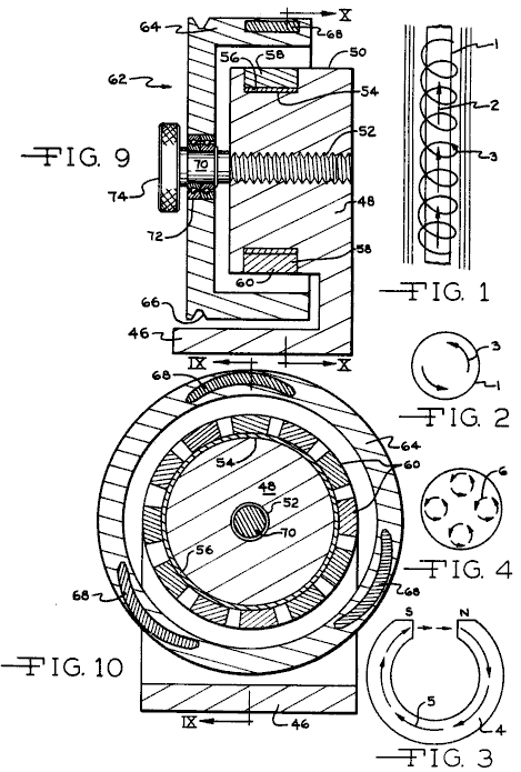
HOWARD JOHNSON: PERMANENT MAGNET MOTOR
Patent US 4,151,431
24th April 1979
Inventor: Howard R. Johnson
PERMANENT MAGNET MOTOR
This is a re-worded extract from this Patent. It describes a motor powered solely by permanent magnets and which it is claimed can power an electrical generator.
ABSTRACT
The invention is directed to the method of utilising the unpaired electron spins in ferromagnetic and other materials as a source of magnetic fields for producing power without any electron flow as occurs in normal conductors, and to permanent magnet motors for utilising this method to produce a power source. In the practice of the invention the unpaired electron spins occurring within permanent magnets are utilised to produce a motive power source solely through the superconducting characteristics of a permanent magnet, and the magnetic flux created by the magnets is controlled and concentrated to orientate the magnetic forces generated in such a manner to produce useful continuous work, such as the displacement of a rotor with respect to a stator. The timing and orientation of magnetic forces at the rotor and stator components produced by the permanent magnets is accomplished by the proper geometrical relationship of these components.
BACKGROUND OF THE INVENTION:
Conventional electric motors employ magnetic forces to produce either rotational or linear motion. Electric motors operate on the principal that when a conductor which carries a current is located in a magnetic field, a magnetic force is exerted upon it. Normally, in a conventional electric motor, the rotor, or stator, or both, are so wired that magnetic fields created by electromagnets use attraction, repulsion, or both types of magnetic forces, to impose a force upon the armature causing rotation, or linear displacement of the armature. Conventional electric motors may employ permanent magnets either in the armature or stator components, but to date they require the creation of an electromagnetic field to act upon the permanent magnets. Also, switching gear is needed to control the energising of the electromagnets and the orientation of the magnetic fields producing the motive power.
It is my belief that the full potential of magnetic forces existing in permanent magnets has not been recognised or utilised because of incomplete information and theory with respect to atomic motion occurring within a permanent magnet. It is my belief that a presently unnamed atomic particle is associated with the electron movement of a superconducting electromagnet and the loss-less flow of currents in permanent magnets. The unpaired electron flow is similar in both situations. This small particle is believed to be opposite in charge to an electron and to be located at right angles to the moving electron. This particle must be very small to penetrate all known elements in their various states as well as their known compounds (unless they have unpaired electrons which capture these particles as they endeavour to pass through).
The electrons in ferrous materials differ from those found in most elements in that they are unpaired, and being unpaired they spin around the nucleus in such a way that they respond to magnetic fields as well as creating a magnetic field themselves. If they were paired, their magnetic fields would cancel out. However, being unpaired they create a measurable magnetic field if their spins are orientated in one direction. The spins are at right angles to their magnetic fields.
In niobium superconductors, at a critical state, the magnetic lines of force cease to be at right angles. This change must be due to establishing the required conditions for unpaired electronic spins instead of electron flow in the conductor, and the fact that very powerful electromagnets can be formed with superconductors illustrates the tremendous advantage of producing the magnetic field by unpaired electron spins rather than conventional electron flow. In a superconducting metal, wherein the electrical resistance becomes greater in the metal than the proton resistance, the flow turns to electron spins and the positive particles flow parallel in the metal in the manner occurring in a permanent magnet where a powerful flow of magnetic positive particles or magnetic flux causes the unpaired electrons to spin at right angles. Under cryogenic superconduction conditions the freezing of the crystals in place makes it possible for the spins to continue, and in a permanent magnet the grain orientation of the magnetised material allows these spins, permitting them to continue and causing the flux to flow parallel to the metal. In a superconductor, at first the electron is flowing and the positive particle is spinning; later, when critical, the reverse occurs, i.e., the electron is spinning and the positive particle is flowing at right angles. These positive particles will thread or work their way through the electron spins present in the metal.
In a sense, a permanent magnet may be considered a room-temperature superconductor. It is a superconductor because the electron flow does not cease, and this electron flow can be made to do work through the magnetic field which it creates. Previously, this source of power has not been used because it was not possible to modify the electron flow to accomplish the switching functions of the magnetic field. Such switching functions are common in a conventional electric motor where electrical current is employed to align the much greater electron current in the iron pole pieces and concentrate the magnetic field at the proper places to give the thrust necessary to move the motor armature. In a conventional electric motor, switching is accomplished by the use of brushes, commutators, alternating current, or other means.
In order to accomplish the switching function in a permanent magnet motor, it is necessary to shield the magnetic leakage so that it will not appear as too great a loss factor at the wrong places. The best method to accomplish this is to concentrate the magnetic flux in the place where it will be the most effective. Timing and switching can be achieved in a permanent magnet motor by concentrating the flux and using the proper geometry of the motor rotor and stator to make most effective use of the magnetic fields. By the proper combination of materials, geometry and magnetic concentration, it is possible to achieve a mechanical advantage of high ratio, greater than 100 to 1, capable of producing continuous motive force.
To my knowledge, previous work done with permanent magnets, and motive devices utilising permanent magnets, have not achieved the result desired in the practice of the inventive concept, and it is with the proper combination of materials, geometry and magnetic concentration that the presence of the magnetic spins within a permanent magnet may be utilised as a motive force.
SUMMARY OF THE INVENTION:
It is an object of the invention to utilise the magnetic spinning phenomenon of unpaired electrons occurring in ferromagnetic material to produce the movement of a mass in a unidirectional manner so as to permit a motor to be driven solely by the magnetic forces occurring within permanent magnets. Both linear and rotational types of motor may be produced. It is an object of the invention to provide the proper combination of materials, geometry and magnetic concentration to power a motor. Whether the motor is a linear type or a rotary type, in each instance the "stator" may consist of several permanent magnets fixed relative to each other, to create a track. This track is linear for a linear motor and circular for a rotary motor. An armature magnet is carefully positioned above this track so that an air gap exists between it and the track. The length of the armature magnet is defined by poles of opposite polarity, and the longer axis of the armature magnet is pointed in the direction of its movement.
The stator magnets are mounted so that all the same poles face the armature magnet. The armature magnet has poles which are both attracted to and repelled by the adjacent pole of the stator magnets, so both attractive and repulsive forces act upon the armature magnet to make it move.
The continuing motive force which acts on the armature magnet is caused by the relationship of the length of the armature magnet to the width and spacing of the stator magnets. This ratio of magnet and magnet spacings, and with an acceptable air gap spacing between the stator and armature magnets, produces a continuous force which causes the movement of the armature magnet.
In the practice of the invention, movement of the armature magnet relative to the stator magnets results from a combination of attractive and repulsive forces between the stator and armature magnets. By concentrating the magnetic fields of the stator and armature magnets the motive force imposed upon the armature magnet is intensified, and in the disclosed embodiments, the means for achieving this magnetic field concentration are shown.
This method comprises of a plate of high magnetic field permeability placed behind one side of the stator magnets and solidly engaged with them. The magnetic field of the armature magnet may be concentrated and directionally oriented by bowing the armature magnet, and the magnetic field may further be concentrated by shaping the pole ends of the armature magnet to concentrate the magnet field at a relatively limited surface at the armature magnet pole ends.
Preferably, several armature magnets are used and these are staggered relative to each other in the direction their movement. Such an offsetting or staggering of the armature magnets distributes the impulses of force imposed upon the armature magnets and results in a smoother application of forces to the armature magnet producing a smoother and more uniform movement of the armature component.
In the rotary embodiment of the permanent magnet motor of the invention the stator magnets are arranged in a circle, and the armature magnets rotate about the stator magnets. A mechanism is shown which can move the armature relative to the stator and this controls the magnitude of the magnetic forces, altering the speed of rotation of the motor.
BRIEF DESCRIPTION OF THE DRAWINGS
The objects and advantages of the invention mentioned earlier, will be appreciated from the following description and accompanying drawings:
Fig. 1 is a schematic view of electron flow in a superconductor indicating the unpaired electron spins,
Fig. 2 is a cross-sectional view of a superconductor under a critical state illustrating the electron spins,
Fig. 3 is a view of a permanent magnet illustrating the flux movement through it,
Fig. 4 is a cross-sectional view illustrating the diameter of the magnet of Fig.3,
Fig. 5 is an elevational representation of a linear motor embodiment of the permanent magnet motor of the invention illustrating one position of the armature magnet relative to the stator magnets, and indicating the magnetic forces imposed upon the armature magnet,
Fig. 6 is a view similar to Fig.5
illustrating displacement of the armature magnet relative to the stator
magnets, and the influence of magnetic forces thereon at this location,
Fig. 7 is a further elevational view similar to Fig.5 and Fig.6 illustrating further displacement of the armature magnet to the left, and the influence of the magnetic forces thereon,
Fig. 8 is a top plan view of a linear embodiment of the inventive concept illustrating a pair of armature magnets in linked relationship disposed above the stator magnets,
Fig. 9 is a diametrical, elevational, sectional view of a rotary motor embodiment in accord with the invention as taken along section IX-IX of Fig.10, and
Fig. 10 is an elevational view of the rotary motor embodiment as taken along X-X of Fig.9.

DESCRIPTION OF THE PREFERRED EMBODIMENTS
In order to better understand the theory of the inventive concept, reference is made to Figs. 1 through 4. In Fig.1 a superconductor 1 is illustrated having a positive particle flow as represented by arrow 2, the unpaired electrons of the ferrous conductor 1 spin at right angles to the proton flow in the conductor as represented by the spiral line and arrow 3. In accord with the theory of the invention the spinning of the ferrous unpaired electrons results from the atomic structure of ferrous materials and this spinning atomic particle is believed to be opposite in charge and located at right angles to the moving electrons. It is assumed to be very small in size capable of penetrating other elements and their compounds unless they have unpaired electrons which capture these particles as they endeavour to pass through.
The lack of electrical resistance of conductors at a critical superconductor state has long been recognised, and superconductors have been utilised to produce very high magnetic flux density electromagnets. Fig.2 represents a cross section of a critical superconductor and the electron spins are indicated by the arrows 3. A permanent magnet may be considered a superconductor as the electron flow therein does not cease, and is without resistance, and unpaired electric spinning particles exist which, in the practice of the invention, are utilised to produce motor force. Fig.3 illustrates a horseshoe shaped permanent magnet at 4 and the magnetic flux through it is indicated by arrows 5, the magnetic flow being from the south pole to the north pole and through the magnetic material. The accumulated electron spins occurring about the diameter of the magnet 5 are represented at 6 in Fig.4, and the spinning electron particles spin at right angles in the iron as the flux travels through the magnet material.
By utilising the electron spinning theory of ferrous material electrons, it is possible with the proper ferromagnetic materials, geometry and magnetic concentration to utilise the spinning electrons to produce a motive force in a continuous direction, thereby resulting in a motor capable of doing work.
It is appreciated that the embodiments of motors utilising the concepts of the invention may take many forms, and in the illustrated forms the basic relationships of components are illustrated in order to disclose the inventive concepts and principles. The relationships of the plurality of magnets defining the stator 10 are best appreciated from Figs. 5 through 8. The stator magnets 12 are preferably of a rectangular configuration, Fig.8, and so magnetised that the poles exist at the large surfaces of the magnets, as will be appreciated from the N (North) and S (South) designations. The stator magnets include side edges 14 and 16 and end edges 18. The stator magnets are mounted upon a supporting plate 20, which is preferably of a metal having a high permeability to magnetic fields and magnetic flux such as that available under the trademark Netic CoNetic sold by Perfection Mica Company of Chicago, Illinois. Thus, the plate 20 will be disposed toward the south pole of the stator magnets 12, and preferably in direct engagement therewith, although a bonding material may be interposed between the magnets and the plate in order to accurately locate and fix the magnets on the plate, and position the stator magnets with respect to each other.
Preferably, the spacing between the stator magnets 12 slightly differs between adjacent stator magnets as such a variation in spacing varies the forces being imposed upon the armature magnet at its ends, at any given time, and thus results in a smoother movement of the armature magnet relative to the stator magnets. Thus, the stator magnets so positioned relative to each other define a track 22 having a longitudinal direction left to right as viewed in Figs. 5 through 8.
In Figs. 5 through 7 only a single armature magnet 24 is disclosed, while in Fig.8 a pair of armature magnets are shown. For purposes of understanding the concepts of the invention the description herein will be limited to the use of single armature magnet as shown in Figs. 5 through 7.
The armature magnet is of an elongated configuration wherein the length extends from left to right, Fig.5, and may be of a rectangular transverse cross-sectional shape. For magnetic field concentrating and orientation purposes the magnet 24 is formed in an arcuate bowed configuration as defined by concave surfaces 26 and convex surfaces 28, and the poles are defined at the ends of the magnet as will be appreciated from Fig.5. For further magnetic field concentrating purposes the ends of the armature magnet are shaped by bevelled surfaces 30 to minimise the cross sectional area at the magnet ends 32, and the magnetic flux existing between the poles of the armature magnet are as indicated by the light dotted lines. In like manner the magnetic fields of 6 the stator magnets 12 are indicated by the light dotted lines.
The armature magnet 24 is maintained in a spaced relationship above the stator track 22. This spacing may be accomplished by mounting the armature magnet upon a slide, guide or track located above the stator magnets, or the armature magnet could be mounted upon a wheeled vehicle carriage or slide supported upon a non-magnetic surface or guideway disposed between the stator magnets and the armature magnet. To clarify the illustration, the means for supporting the armature magnet 24 is not illustrated and such means form no part of invention, and it is to be understood that the means supporting the armature magnet prevents the armature magnet from moving away from the stator magnets, or moving closer thereto, but permits free movement of the armature magnet to the left or right in a direction parallel to the track 22 defined by the stator magnets.
It will be noted that the length of the armature magnet 24 is slightly greater than the width of two of the stator magnets 12 and the spacing between them. The magnetic forces acting upon the armature magnet when in the position of Fig.5 will be repulsion forces 34 due to the proximity of like polarity forces and attraction forces at 36 because of the opposite polarity of the south pole of the armature magnet, and the north pole field of the sector magnets. The relative strength of this force is represented by the thickness of the force line.
The resultant of the force vectors imposed upon the armature magnet as shown in Fig.5 produce a primary force vector 38 toward the left, Fig.5, displacing the armature magnet 24 toward the left. In Fig.6 the magnetic forces acting upon the armature magnet are represented by the same reference numerals as in Fig.5. While the forces 34 constitute repulsion forces tending to move the north pole of the armature magnet away from the stator magnets, the attraction forces imposed upon the south pole of the armature magnet and some of the repulsion forces, tend to move the armature magnet further to the left, and as the resultant force 38 continues to be toward the left the armature magnet continues to be forced to the left. Fig.7 represents further displacement of the armature magnet 24 to the left with respect to the position of Fig.6, and the magnetic forces acting thereon are represented by the same reference numerals as in Fig.5 and Fig.6, and the stator magnet will continue to move to the left, and such movement continues the length of the track 22 defined by the stator magnets 12.
Upon the armature magnet being reversed such that the north pole is positioned at the right as viewed in Fig.5, and the south pole is positioned at the left, the direction of movement of the armature magnet relative to the stator magnets is toward the right, and the theory of movement is identical to that described above.
In Fig.8 a plurality of armature magnets 40 and 42 are illustrated which are connected by links 44. The armature magnets are of a shape and configuration identical to that of the embodiment of Fig.5, but the magnets are staggered with respect to each other in the direction of magnet movement, i.e., the direction of the track 22 defined by the stator magnets 12. By so staggering a plurality of armature magnets a smoother movement of the interconnected armature magnets is produced as compared when using a single armature magnet as there is variation in the forces acting upon each armature magnet as it moves above the track 22 due to the change in magnetic forces imposed thereon. The use of several armature magnets tends to "smooth out" the application of forces imposed upon linked armature magnets, resulting in a smoother movement of the armature magnet assembly. Of course, any number of armature magnets may be interconnected, limited only by the width of the stator magnet track 22.
In Fig.9 and Fig.10 a rotary embodiment embracing the inventive concepts is illustrated. In this embodiment the principle of operation is identical to that described above, but the orientation of the stator and armature magnets is such that rotation of the armature magnets is produced about an axis, rather than a linear movement being achieved.
In Fig.9 and Fig.10 a base is represented at 46 serving as a support for a stator member 48. The stator member 48 is made of a non-magnetic material, such as synthetic plastic, aluminium, or the like. The stator includes a cylindrical surface 50 having an axis, and a threaded bore 52 is concentrically defined in the stator. The stator includes an annular groove 54 receiving an annular sleeve 56 of high magnetic field permeability material such as Netic Co-Netic and a plurality of stator magnets 58 are affixed upon the sleeve 56 in spaced circumferential relationship as will be apparent in Fig.10. Preferably, the stator magnets 58 are formed with converging radial sides as to be of a wedge configuration having a curved inner surface engaging sleeve 56, and a convex pole surface 60.
The armature 62, in the illustrated embodiment, is of a dished configuration having a radial web portion, and an axially extending portion 64. The armature 62 is formed of a non-magnetic material, and an annular belt receiving groove 66 is defined therein for receiving a belt for transmitting power from the armature to a generator, or other power consuming device. Three armature magnets 68 are mounted on the armature portion 64, and such magnets are of a configuration similar to the armature magnet configuration of Figs. 5 through 7.
The magnets 68 are staggered with respect to each other in a circumferential direction wherein the magnets are not placed exactly 120 degrees apart but instead, a slight angular staggering of the armature magnets is desirable to "smooth out" the magnetic forces being imposed upon the armature as a result of the magnetic forces being simultaneously imposed upon each of the armature magnets. The staggering of the armature magnets 68 in a circumferential direction produces the same effect as the staggering of the armature magnets 40 and 42 as shown in Fig.8.
The armature 62 is mounted upon a threaded shaft 70 by anti-friction bearings 72, and the shaft 70 is threaded into the stator threaded bore 52, and may be rotated by the knob 74. In this manner rotation of the knob 74, and shaft 70, axially displaces the armature 62 with respect to the stator magnets 58, and such axial displacement will very the magnitude of the magnetic forces imposed upon the armature magnets 68 by the stator magnets thereby controlling the speed of rotation of the armature. As will be noted from Figs. 4 to 7, 9 and 10, an air gap exists between the armature magnets and the stator magnets and the dimension of this spacing, effects the magnitude of the forces imposed upon the armature magnet or magnets. If the distance between the armature magnets and the stator magnets is reduced the forces imposed upon the armature magnets by the stator magnets are increased, and the resultant force 8 vector tending to displace the armature magnets in their path of movement increases. However, the decreasing of the spacing between the armature and stator magnets creates a "pulsation" in the movement of the armature magnets which is objectionable, but can be, to some extent, minimised by using a plurality of armature magnets. Increasing the distance between the armature and stator magnets reduces the pulsation tendency of the armature magnet, but also reduces the magnitude of the magnetic forces imposed upon the armature magnets. Thus, the most effective spacing between the armature and stator magnets is that spacing which produces the maximum force vector in the direction of armature magnet movement, with a minimum creation of objectionable pulsation.
In the disclosed embodiments the high permeability plate 20 and sleeve 56 are disclosed for concentrating the magnetic field of the stator magnets, and the armature magnets are bowed and have shaped ends for magnetic field concentration purposes. While such magnetic field concentration means result in higher forces imposed upon the armature magnets for given magnet intensities, it is not intended that the inventive concepts be limited to the use of such magnetic field concentrating means.
As will be appreciated from the above description of the invention, the movement of the armature magnet or magnets results from the described relationship of components. The length of the armature magnets as related to the width of the stator magnets and spacing between them, the dimension of the air gap and the configuration of the magnetic field, combined, produce the desired result and motion. The inventive concepts may be practised even though these relationships may be varied within limits not yet defined and the invention is intended to encompass all dimensional relationships which achieve the desired goal of armature movement. By way of example, with respect to Figs. to 7, the following dimensions were used in an operating prototype:
The length of armature magnet 24 is 3.125", the stator magnets 12 are 1" wide, .25" thick and 4" long and grain oriented. The air gap between the poles of the armature magnet and the stator magnets is approximately 1.5" and the spacing between the stator magnets is approximately .5" inch.
In effect, the stator magnets define a magnetic field track of a single polarity transversely interrupted at spaced locations by the magnetic fields produced by the lines of force existing between the poles of the stator magnets and the unidirectional force exerted on the armature magnet is a result of the repulsion and attraction forces existing as the armature magnet traverses this magnetic field track.
It is to be understood that the inventive concept embraces an arrangement wherein the armature magnet component is stationary and the stator assembly is supported for movement and constitutes the moving component, and other variations of the inventive concept will be apparent to those skilled in the art without departing from the scope thereof. As used herein the term "track" is intended to include both linear and circular arrangements of the static magnets, and the "direction" or "length" of the track is that direction parallel or concentric to the intended direction of armature magnet movement.
PAVEL IMRIS: OPTICAL GENERATOR
US Patent
3,781,601 25th December
1973 Inventor: Pavel Imris
OPTICAL GENERATOR OF AN ELECTROSTATIC
FIELD HAVING LONGITUDINAL OSCILLATION AT LIGHT FREQUENCIES FOR USE IN AN
ELECTRICAL CIRCUIT
Please note
that this is a re-worded excerpt from this patent. It describes a gas-filled tube which allows
many standard 40-watt fluorescent tubes to be powered using less than 1-watt of
power each.
ABSTRACT
An Optical generator of an electrostatic field at light frequencies for use in an electrical circuit, the generator having a pair of spaced-apart electrodes in a gas-filled tube of quartz glass or similar material with at least one capacitor cap or plate adjacent to one electrode and a dielectric filled container enclosing the tube, the generator substantially increasing the electrical efficiency of the electrical circuit.
BACKGROUND OF THE INVENTION
This invention relates to improved electrical circuits, and more particularly to circuits utilising an optical generator of an electrostatic field at light frequencies.
The measure of the efficiency of an electrical circuit may broadly be defined as the ratio of the output energy in the desired form (such as light in a lighting circuit) to the input electrical energy. Up to now, the efficiency of many circuits has not been very high. For example, in a lighting circuit using 40 watt fluorescent lamps, only about 8.8 watts of the input energy per lamp is actually converted to visible light, thus representing an efficiency of only about 22%. The remaining 31.2 watts is dissipated primarily in the form of heat.
It has been suggested that with lighting circuits having fluorescent lamps, increasing the frequency of the applied current will raise the overall circuit efficiency. While at an operating frequency of 60 Hz, the efficiency is 22%, if the frequency is raised to 1 Mhz, the circuit efficiency would only rise to some 25.5%. Also, if the input frequency were raised to 10 Ghz, the overall circuit efficiency would only be 35%.
SUMMARY OF THE PRESENT INVENTION
The present invention utilises an optical electrostatic generator which is effective for producing high frequencies in the visible light range of about 1014 to 1023 Hz. The operation and theory of the optical electrostatic generator has been described and discussed in my co-pending application serial No. 5,248, filed on 23rd January 1970. As stated in my co-pending application, the present optical electrostatic generator does not perform in accordance with the accepted norms and standards of ordinary electromagnetic frequencies.
The optical electrostatic generator as utilised in the present invention can generate a wide range of frequencies between several Hertz and those in the light frequency. Accordingly, it is an object of the present invention to provide improved electrical energy circuits utilising my optical electrostatic generator, whereby the output energy in the desired form will be substantially more efficient than possible to date, using standard circuit techniques and equipment. It is a further object of the present invention to provide such a circuit for use in fluorescent lighting or other lighting circuits. It is also an object of the present invention to provide a circuit with may be used in conjunction with electrostatic precipitators for dust and particle collection and removal, as well as many other purposes.
DESCRIPTION OF THE DRAWINGS
Fig.1 is a schematic layout showing an optical electrostatic generator of the present invention, utilised in a lighting circuit for fluorescent lamps:
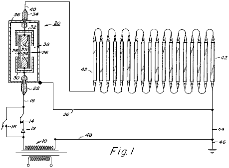
Fig.2 is a schematic layout of a high-voltage circuit incorporating an optical electrostatic generator:

Fig.2A is a sectional view through a portion of the generator and
Fig.3 is a schematic sectional view showing an optical electrostatic generator in accordance with the present invention, particularly for use in alternating current circuits, although it may also be used in direct current circuits:
DESCRIPTION OF THE ILLUSTRATED EMBODIMENTS
Referring to the drawings and to Fig.1 in particular, a low voltage circuit utilising an optical electrostatic generator is shown. As shown in Fig.1, a source of alternating current electrical energy 10, is connected to a lighting circuit. Connected to one tap of the power source 10 is a rectifier 12 for utilisation when direct current is required. The illustrated circuit is provided with a switch 14 which may be opened or closed depending on whether AC or DC power is used. Switch 14 is opened and a switch 16 is closed when AC is used. With switch 14 closed and switch 16 open, the circuit operates as a DC circuit.
Extending from switches 14 and 16 is conductor 18 which is connected to an optical electrostatic generator 20. Conductor 18 is passed through an insulator 22 and connected to an electrode 24. Spaced from electrode 24 is a second electrode 25. Enclosing electrodes 24 and 25, which preferably are made of tungsten or similar material, is a quartz glass tube 26 which is filled with an ionisable gas 28 such as xenon or any other suitable ionisable gas such as argon, krypton, neon, nitrogen or hydrogen, as well as the vapour of metals such as mercury or sodium.
Surrounding each end of tube 26 and adjacent to electrodes 24 and 25, are capacitor plates 30 and 32 in the form of caps. A conductor is connected to electrode 25 and passed through a second insulator 34. Surrounding the tube, electrodes and capacitor caps is a metal envelope in the form of a thin sheet of copper or other metal such as aluminium. Envelope 36 is spaced from the conductors leading into and out of the generator by means of insulators 22 and 34. Envelope 36 is filled with a dielectric material such as transformer oil, highly purified distilled water, nitro-benzene or any other suitable liquid dielectric. In addition, the dielectric may be a solid such as ceramic material with relatively small molecules.
A conductor 40 is connected to electrode 25, passed through insulator 24 and then connected to a series of fluorescent lamps 42 which are connected in series. It is the lamps 42 which will be the measure of the efficiency of the circuit containing the optical electrostatic generator 20. A conductor 44 completes the circuit from the fluorescent lamps to the tap of the source of electrical energy 10. In addition, the circuit is connected to a ground 46 by another conductor 48. Envelope 36 is also grounded by lead 50 and in the illustrated diagram, lead 50 is connected to the conductor 44.
The capacitor caps or plates 30 and 32, form a relative capacitor with the discharge tube. When a high voltage is applied to the electrode of the discharge tube, the ions of gas are excited and brought to a higher potential than their environment, i.e. the envelope and the dielectric surrounding it. At this point, the ionised gas in effect becomes one plate of a relative capacitor in co-operation with the capacitor caps or plates 30 and 32.
When this relative capacitor is discharged, the electric current does not decrease as would normally be expected. Instead, it remains substantially constant due to the relationship between the relative capacitor and an absolute capacitor which is formed between the ionised gas and the spaced metal envelope 36. An oscillation effect occurs in the relative capacitor, but the electrical condition in the absolute capacitor remains substantially constant.
As also described in the co-pending application serial No. 5,248, there is an oscillation effect between the ionised gas in the discharge lamp and the metallic envelope 36 will be present if the capacitor caps are eliminated, but the efficiency of the electrostatic generator will be substantially decreased.
The face of the electrode can be any desired shape. However, a conical point of 600 has been found to be satisfactory and it is believed to have an influence on the efficiency of the generator.
In addition, the type of gas selected for use in tube 26, as well as the pressure of the gas in the tube, also affect the efficiency of the generator, and in turn, the efficiency of the electrical circuit.
To demonstrate the increased efficiency of an electrical circuit utilising the optical electrostatic generator of the present invention as well as the relationship between gas pressure and electrical efficiency, a circuit similar to that shown in Fig.1 may be used with 100 standard 40 watt, cool-white fluorescent lamps connected in series. The optical electrostatic generator includes a quartz glass tube filled with xenon, with a series of different tubes being used because of the different gas pressures being tested.
Table 1 shows the data to be obtained relating to the optical electrostatic generator. Table 2 shows the lamp performance and efficiency for each of the tests shown in Table 1. The following is a description of the data in each of the columns of Tables 1 and 2.
|
Column |
Description |
|
B |
Gas used in discharge tube |
|
C |
Gas pressure in tube (in torrs) |
|
D |
Field strength across the tube (measured in volts per cm. of length between the electrodes) |
|
E |
Current density (measured in microamps per sq. mm. of tube cross-sectional area) |
|
F |
Current (measured in amps) |
|
G |
Power across the tube (calculated in watts per cm. of length between the electrodes) |
|
H |
Voltage per lamp (measured in volts) |
|
K |
Current (measured in amps) |
|
L |
Resistance (calculated in ohms) |
|
M |
Input power per lamp (calculated in watts) |
|
N |
Light output (measured in lumens) |
Table 1
|
|
|
Optical |
Generator |
Section |
|
|
|
A |
B |
C |
D |
E |
F |
G |
|
Test No. |
Type of discharge
lamp |
Pressure of Xenon |
Field strength across lamp |
Current density |
Current |
Power str. across lamp |
|
|
|
(Torr) |
(V/cm) |
(A/sq.mm) |
(A) |
(W/cm.) |
|
1 |
Mo elec |
- |
- |
- |
- |
- |
|
2 |
Xe |
0.01 |
11.8 |
353 |
0.1818 |
2.14 |
|
3 |
Xe |
0.10 |
19.6 |
353 |
0.1818 |
3.57 |
|
4 |
Xe |
1.00 |
31.4 |
353 |
0.1818 |
5.72 |
|
5 |
Xe |
10.00 |
47.2 |
353 |
0.1818 |
8.58 |
|
6 |
Xe |
20.00 |
55.1 |
353 |
0.1818 |
10.02 |
|
7 |
Xe |
30.00 |
62.9 |
353 |
0.1818 |
11.45 |
|
8 |
Xe |
40.00 |
66.9 |
353 |
0.1818 |
12.16 |
|
9 |
Xe |
60.00 |
70.8 |
353 |
0.1818 |
12.88 |
|
10 |
Xe |
80.00 |
76.7 |
353 |
0.1818 |
13.95 |
|
11 |
Xe |
100.00 |
78.7 |
353 |
0.1818 |
14.31 |
|
12 |
Xe |
200.00 |
90.5 |
353 |
0.1818 |
16.46 |
|
13 |
Xe |
300.00 |
100.4 |
353 |
0.1818 |
18.25 |
|
14 |
Xe |
400.00 |
106.3 |
353 |
0.1818 |
19.32 |
|
15 |
Xe |
500.00 |
110.2 |
353 |
0.1818 |
20.04 |
|
16 |
Xe |
600.00 |
118.1 |
353 |
0.1818 |
21.47 |
|
17 |
Xe |
700.00 |
120.0 |
353 |
0.1818 |
21.83 |
|
18 |
Xe |
800.00 |
122.8 |
353 |
0.1818 |
22.33 |
|
19 |
Xe |
900.00 |
125.9 |
353 |
0.1818 |
22.90 |
|
20 |
Xe |
1,000.00 |
127.9 |
353 |
0.1818 |
23.26 |
|
21 |
Xe |
2,000.00 |
149.6 |
353 |
0.1818 |
27.19 |
|
22 |
Xe |
3,000.00 |
161.4 |
353 |
0.1818 |
29.35 |
|
23 |
Xe |
4,000.00 |
173.2 |
353 |
0.1818 |
31.49 |
|
24 |
Xe |
5,000.00 |
179.1 |
353 |
0.1818 |
32.56 |
Table 2
|
|
|
Fluorescent |
Lamp |
Section |
|
|
A |
H |
K |
L |
M |
N |
|
Test No. |
Voltage |
Current |
Resistance |
Input Energy |
Light Output |
|
|
(Volts) |
(Amps) |
(Ohms) |
( |
(Lumen) |
|
1 |
220 |
0.1818 |
1,210 |
40.00 |
3,200 |
|
2 |
218 |
0.1818 |
1,199 |
39.63 |
3,200 |
|
3 |
215 |
0.1818 |
1,182 |
39.08 |
3,200 |
|
4 |
210 |
0.1818 |
1,155 |
38.17 |
3,200 |
|
5 |
200 |
0.1818 |
1,100 |
36.36 |
3,200 |
|
6 |
195 |
0.1818 |
1,072 |
35.45 |
3,200 |
|
7 |
190 |
0.1818 |
1,045 |
34.54 |
3,200 |
|
8 |
182 |
0.1818 |
1,001 |
33.08 |
3,200 |
|
9 |
175 |
0.1818 |
962 |
31.81 |
3,200 |
|
10 |
162 |
0.1818 |
891 |
29.45 |
3,200 |
|
11 |
155 |
0.1818 |
852 |
28.17 |
3,200 |
|
12 |
130 |
0.1818 |
715 |
23.63 |
3,200 |
|
13 |
112 |
0.1818 |
616 |
20.36 |
3,200 |
|
14 |
100 |
0.1818 |
550 |
18.18 |
3,200 |
|
15 |
85 |
0.1818 |
467 |
15.45 |
3,200 |
|
16 |
75 |
0.1818 |
412 |
13.63 |
3,200 |
|
17 |
67 |
0.1818 |
368 |
12.18 |
3,200 |
|
18 |
60 |
0.1818 |
330 |
10.90 |
3,200 |
|
19 |
53 |
0.1818 |
291 |
9.63 |
3,200 |
|
20 |
50 |
0.1818 |
275 |
9.09 |
3,200 |
|
21 |
23 |
0.1818 |
126 |
4.18 |
3,200 |
|
22 |
13 |
0.1818 |
71 |
2.35 |
3,200 |
|
23 |
8 |
0.1818 |
44 |
1.45 |
3,200 |
|
24 |
5 |
0.1818 |
27 |
0.90 |
3,200 |
The design of a tube construction for use in the optical electrostatic generator of the type used in Fig.1, may be accomplished by considering the radius of the tube, the length between the electrodes in the tube and the power across the tube.
If R is the minimum inside radius of the
tube in centimetres, L the minimum
length in centimetres between the electrodes, and W the power in watts across the lamp, the following formula can be
obtained from Table 1:
R = (Current [A] / Current Density
[A/sq.mm] ) / pi
L = 8R
W = L[V/cm] x A
For example, for Test No. 18 in Table 1:
The current is 0.1818 A,
The current density 0.000353 A/sq.mm and
The Voltage Distribution is 122.8 V/cm; therefore
R = (0.1818 / 0.000353)2 /3.14 = 12.80 mm.
L = 8 x R = 8 * 12.8 = 102.4 mm (10.2 cm.)
W = 10.2 x 122.8 x 0.1818 = 227.7 VA or 227.7 watts
The percent efficiency of operation of the fluorescent lamps in Test No. 18 can be calculated from the following equation:
% Efficiency = (Output Energy/Input energy) x 100
Across a single fluorescent lamp, the voltage is 60 volts and the current is 0.1818 amps therefore the input energy to the lamp 42 is 10.90 Watts. The output of the fluorescent lamp is 3,200 lumens which represents 8.8 Watts power of light energy. Thus, the one fluorescent lamp is operating at 80.7% efficiency under these conditions.
However, when the optical generator is the same as described for Test No. 18 and there are 100 fluorescent lamps in series in the circuit, the total power input is 227.7 watts for the optical generator and 1,090 watts for 100 fluorescent lamps, or a total of 1,318 watts. The total power input normally required to operate the 100 fluorescent lamps in a normal circuit would be 100 x 40 = 4,000 watts. So by using the optical generator in the circuit, about 2,680 watts of energy is saved.
Table 1 is an example of the functioning of this invention for a particular fluorescent lamp (40 watt cool white). However, similar data can be obtained for other lighting applications, by those skilled in the art.
In Fig.2, a circuit is shown which uses an optical electrostatic generator 20a, similar to generator 20 of Fig.1. In generator 20, only one capacitor cap 32a is used and it is preferably of triangular cross-sectional design. In addition, the second electrode 25a is connected directly back into the return conductor 52, similar to the arrangement shown in my co-pending application serial No. 5,248, filed 23rd January 1970.
This arrangement is preferably for very high voltage circuits and the generator is particularly suited for DC usage.
In Fig.2, common elements have received the same numbers which were used in Fig.1.
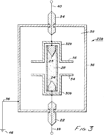
In Fig.3, still another embodiment of an optical electrostatic generator 20b is shown. This generator is particularly suited for use with AC circuits. In this embodiment, the capacitor plates 30b and 32b have flanges 54 and 56 which extend outwards towards the envelope 36. While the utilisation of the optical electrostatic generator has been described in use in a fluorescent lighting circuit, it is to be understood that many other types of circuits may be used. For example, the high-voltage embodiment may be used in a variety of circuits such as flash lamps, high-speed controls, laser beams and high-energy pulses. The generator is also particularly usable in a circuit including electrostatic particle precipitation in air pollution control devices, chemical synthesis in electrical discharge systems such as ozone generators and charging means for high-voltage generators of the Van de Graff type, as well as particle accelerators. To those skilled in the art, many other uses and circuits will be apparent.
HAROLD COLMAN & RONALD SEDDON-GILLESPIE: 70-YEAR BATTERY
Patent GB 763,062 5th December 1956 Inventors: Harold Colman and Ronald Seddon-Gillespie
APPARATUS FOR PRODUCING AN ELECTRIC CURRENT
This patent shows the details of a lightweight device which can produce electricity using a self-powered electromagnet and chemical salts. The working life of the device before needing a recharge is estimated at some seventy years. The operation is controlled by a transmitter which bombards the chemical sample with 300 MHz radio waves. This produces radioactive emissions from the chemical mixture for a period of one hour maximum, so the transmitter needs to be run for fifteen to thirty seconds once every hour. The chemical mixture is shielded by a lead screen to prevent harmful radiation reaching the user. The output from the tiny device described is estimated to be some 10 amps at 100 to 110 volts DC.
DESCRIPTION
This invention relates to a new apparatus for producing electric current the apparatus being in the form of a completely novel secondary battery. The object of this invention is to provide apparatus of the above kind which is considerably lighter in weight than, and has an infinitely greater life than a known battery or similar characteristics and which can be re-activated as and when required in a minimum of time.
According to the present invention we provide apparatus comprising a generator unit which includes a magnet, a means for suspending a chemical mixture in the magnetic field, the mixture being composed of elements whose nuclei becomes unstable as a result of bombardment by short waves so that the elements become radio-active and release electrical energy, the mixture being mounted between, and in contact with, a pair of different metals such as copper and zinc, a capacitor mounted between those metals, a terminal electrically connected to each of the metals, means for conveying the waves to the mixture and a lead shield surrounding the mixture to prevent harmful radiation from the mixture.
The mixture is preferably composed of the elements Cadmium, Phosphorus and Cobalt having Atomic Weights of 112, 31 and 59 respectively. The mixture, which may be of powdered form, is mounted in a tube of non-conducting, high heat resistivity material and is compressed between granulated zinc at one end of the tube and granulated copper at the other end, the ends of the tube being closed by brass caps and the tube being carried in a suitable cradle so that it is located between the poles of the magnet. The magnet is preferably an electro-magnet and is energised by the current produced by the unit.
The means for conveying the waves to the mixture may be a pair of antennae which are exactly similar to the antennae of the transmitter unit for producing the waves, each antenna projecting from and being secured to the brass cap at each end of the tube.
The transmitter unit which is used for activating the generator unit may be of any conventional type operating on ultra-shortwave and is preferably crystal controlled at the desired frequency.
DESCRIPTION OF THE DRAWINGS
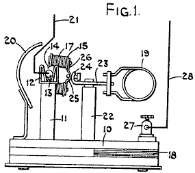
Fig.1 is a side elevation of one form of the apparatus.
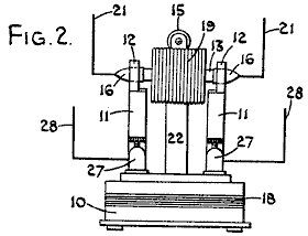
Fig.2 is a view is an end elevation

Fig.3 is a schematic circuit diagram.
In the form of our invention illustrated, the generator unit comprises a base 10 upon which the various components are mounted. This base 10, having projecting upwards from it a pair of arms 11, which form a cradle housing 12 for a quartz tube 13, the cradle 12 preferably being made of spring material so that the tube 13 is firmly, yet removably held in position. The arms 11 are positioned relative to the poles 14 of an electromagnet 15 so that the tube 13 is located immediately between the poles of the magnet so as to be in the strongest magnetic field created by the electromagnet. The magnet serves to control the alpha and beta rays emitted by the cartridge when it is in operation.
The ends of the quartz tube 13 are each provided with a brass cap 16, and these caps 16 are adapted to engage within the spring cradles 12 and the coils 17 associated with the magnet being so arranged that if the base 10 of the unit is in a horizontal plane, the poles 14 of the magnet are in a substantially vertical plane.
Also connected across the cradles is a lead capacitor 18 which may conveniently be housed in the base 10 of the unit and connected in parallel with this capacitor 18 is a suitable high frequency inductance coil 19. The unit is provided with a lead shield 20 so as to prevent harmful radiation from the quartz tube as will be described later.
The quartz tube 13 has mounted in it, at one end, a quantity of granulated copper which is in electrical contact with the brass cap 16 at that end of the tube. Also mounted within the tube and in contact with the granulated copper is a chemical mixture which is in powdered form and which is capable of releasing electrical energy and which becomes radioactive when subjected to bombardment by ultra-short radio waves.
Mounted in the other end of the tube, and in contact with the other end of the powdered chemical mixture is a quantity of granulated zinc which is itself in contact with the brass cap on this end of the tube, the arrangement being that the chemical mixture is compressed between the granulated copper and the granulated zinc.
Projecting outwards from each brass cap 16, and electrically connected to them, is an antenna 21. Each antenna 21 corresponding exactly in dimension, shape and electrical characteristics to the antenna associated with a transmitter unit which is to produce the ultra shortwaves mentioned earlier.
The electromagnet 15 is conveniently carried by a centrally positioned pillar 22 which is secured to the base 10. At the upper end of pillar 22 there is a cross-bar 23, which has the high frequency coil 19 attached to one end of it. The other end of the cross-bar 23 is bent around into the curved shape as shown at 24 and is adapted to bear against a curved portion 25 of the base 26 of the electromagnet 15. A suitable locking device is provided for holding the curved portions 24 and 25 in the desired angular position, so that the position of the poles 14 of the electromagnet can be adjusted about the axis of the quartz tube 13.
The transmitter unit is of any suitable conventional type for producing ultra shortwaves and may be crystal controlled to ensure that it operates at the desired frequency with the necessity of tuning. If the transmitter is only required to operate over a short range, it may conveniently be battery powered but if it is to operate over a greater range, then it may be operated from a suitable electrical supply such as the mains. If the transmitter is to be tuned, then the tuning may be operated by a dial provided with a micrometer vernier scale so that the necessary tuning accuracy may be achieved.
The mixture which is contained within the quartz tube is composed of the elements Cadmium, Phosphorus and Cobalt, having atomic weights 112, 31 and 59 respectively. Conveniently, these elements may be present in the following compounds, and where the tube is to contain thirty milligrams of the mixture, the compounds and their proportions by weight are:
1 Part of Co (No3) 2 6H2O
2 Parts of
CdCl2
3 Parts of 3Ca (Po3) 2 + 10C.
The cartridge which consists of the tube 13 with the chemical mixture in it is preferably composed of a number of small cells built up in series. In other words, considering the cartridge from one end to the other, at one end and in contact with the brass cap, there would be a layer of powdered copper, then a layer of the chemical mixture, then a layer of powdered zinc, a layer of powdered copper, etc. with a layer of powdered zinc in contact with the brass cap at the other end of the cartridge. With a cartridge some forty five millimetres long and five millimetres diameter, some fourteen cells may be included.
The cradles 12 in which the brass caps 16 engage, may themselves form terminals from which the output of the unit may be taken. Alternatively, a pair of terminals 27 may be connected across the cradles 12, these terminals 27 being themselves provided with suitable antennae 28, which correspond exactly in dimensions, shape and electrical characteristics to the antennae associated with the transmitter, these antennae 28, replacing the antennae 21.
In operation with the quartz tube containing the above mixture located between the granulated copper and the granulated zinc and with the tube itself in position between the poles of the magnet, the transmitter is switched on and the ultra shortwaves coming from it are received by the antennae mounted at each end of the tube and in contact with the copper and zinc respectively, the waves being thus passed through the copper and zinc and through the mixture so that the mixture is bombarded by the short waves and the Cadmium, Phosphorus and Cobalt associated with the mixture become radioactive and release electrical energy which is transmitted to the granulated copper and granulated zinc, causing a current to flow between them in a similar manner to the current flow produced by a thermo couple. It has been established that with a mixture having the above composition, the optimum release of energy is obtained when the transmitter is operating at a frequency of 300 MHz.
The provision of a quartz tube is necessary for the mixture evolves a considerable amount of heat while it is reacting to the bombardment of the short waves. It is found that the tube will only last for one hour and that the tube will become discharged after an hours operation, that is to say, the radioactiveness of the tube will only last for one hour and it is therefore necessary, if the unit is to be run continuously, for the transmitter to be operated for a period of some fifteen to thirty seconds duration once every hour.
With a quartz tube having an overall length of some forty five millimetres and an inside diameter of five millimetres and containing thirty milligrams of the chemical mixture, the estimated energy which will be given off from the tube for a discharge of one hour, is 10 amps at between 100 and 110 volts. To enable the tube to give off this discharge, it is only necessary to operate the transmitter at the desired frequency for a period of some fifteen to thirty seconds duration.
The current which is given off by the tube during its discharge is in the form of direct current. During the discharge from the tube, harmful radiations are emitted in the form of gamma rays, alpha rays and beta rays and it is therefore necessary to mount the unit within a lead shield to prevent the harmful radiations from affecting personnel and objects in the vicinity of the unit. The alpha and beta rays which are emitted from the cartridge when it is in operation are controlled by the magnet.
When the unit is connected up to some apparatus which is to be powered by it, it is necessary to provide suitable fuses to guard against the cartridge being short-circuited which could cause the cartridge to explode.
The estimated weight of such a unit including the necessary shielding, per kilowatt hour output, is approximately 25% of any known standard type of accumulator which is in use today and it is estimated that the life of the chemical mixture is probably in the region of seventy to eighty years when under constant use.
It will thus be seen that we have provided a novel form of apparatus for producing an electric current, which is considerably lighter than the standard type of accumulator at present known, and which has an infinitely greater life than the standard type of accumulator, and which can be recharged or reactivated as and when desired and from a remote position depending on the power output of the transmitter. Such form of battery has many applications.
JONG-SOK AN: NO-LOAD GENERATOR
Patent US 6,208,061
27th March 2001
Inventor: Jong-Sok An
NO-LOAD GENERATOR
Electrical power is frequently generated by spinning the shaft of a generator which has some arrangement of coils and magnets contained within it. The problem is that when current is drawn from the take-off coils of a typical generator, it becomes much more difficult to spin the generator shaft. The cunning design shown in this patent overcomes this problem with a simple design in which the effort required to turn the shaft is not altered by the current drawn from the generator.
ABSTRACT
A generator of the present invention is formed of ring permanent magnet trains 2 and 2' attached and fixed on to two orbits 1 and 1' about a rotational axis 3, magnetic induction primary cores 4 and 4' attached and fixed above outer peripheral surfaces of the ring permanent magnet trains 2 and 2' at a predetermined distance from the outer peripheral surfaces, magnetic induction secondary cores 5 and 5' attached and fixed on to the magnetic induction primary cores 4 and 4' and each having two coupling, holes 6 and 6' formed therein, tertiary cores 8 and 8' inserted for coupling respectively into two coupling holes 6 and 6' of each of the associated magnetic induction secondary cores 5 and 5' opposite to each other, and responsive coils 7 and 7'. The ring permanent magnetic trains 2 and 2' are formed of 8 sets of magnets with alternating N and S poles, and magnets associated with each other in the axial direction have opposite polarities respectively and form a pair.
DESCRIPTION
TECHNICAL FIELD
The present invention relates to generators, and particularly to a load-free generator which can maximise the generator efficiency by erasing or eliminating the secondary repulsive load exerted on the rotor during electric power generation.
BACKGROUND ART
The generator is a machine which converts mechanical energy obtained from sources of various types of energy such as physical, chemical or nuclear power energy, for example, into electric energy. Generators based on linear motion have recently been developed while most generators are structured as rotational type generators. Generation of electromotive force by electromagnetic induction is a common principle to generators regardless of their size or whether the generator is AC or DC generator.
The generator requires a strong magnet such as permanent magnet and electromagnet for generating magnetic field as well as a conductor for generating the electromotive force, and the generator is structured to enable one of them to rotate relative to the other. Depending on which of the magnet and the conductor rotates, generators can be classified into rotating-field type generators in which the magnetic field rotates and rotating-armature type generators in which the conductor rotates.
Although the permanent magnet can be used for generating the magnetic field, the electromagnet is generally employed which is formed of a magnetic field coil wound around a core to allow direct current to flow through them. Even if a strong magnet is used to enhance the rotational speed, usually the electromotive force produced from one conductor is not so great. Thus, in a generally employed system, a large number of conductors are provided in the generator and the electromotive forces generated from respective conductare serially added up so as to achieve a high electric power.
As discussed above, a usual generator produces electricity by mechanically rotating a magnet (or permanent magnet) or a conductor (electromagnet, electrically responsive coil and the like) while reverse current generated at this time by magnetic induction (electromagnetic induction) and flowing through the coil causes magnetic force which pulls the rotor so that the rotor itself is subjected to unnecessary load which reaches at least twice the electric power production.
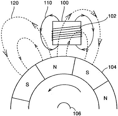
Fig.6 illustrates that the load as discussed above is exerted on a rotor in a rotating-field type generator mentioned above.
Referring to Fig.6, a permanent magnet train 104 is arranged about an axis of rotation 106 such that N poles and S poles are alternately located on the outer peripheral surface of the train. At a certain distance outward from the outer periphery of permanent magnet train 104, a magnetic induction core 100 is arranged and a coil 102 is wound around magnetic induction core 100.
As permanent magnet train 104 rotates, the magnetic field produced in the coil by permanent magnet train 104 changes to cause induced current to flow through coil 102. This induced current allows coil 102 to generate a magnetic field 110 which causes a repulsive force exerted on permanent magnet train 104 in the direction which interferes the rotation of the magnet train.
For example, in the example shown in Fig.6, the S pole of magnetic field 110 faces permanent magnet train 104. The S pole of permanent magnet train 104 approaches coil 102 because of rotation of permanent magnet train 104, resulting in the repulsive force as described above.
If reverse current flows in a responsive coil of an armature wound around a magnetic induction core of a generator so that the resulting load hinders the rotor from rotating, reverse magnetic field of the armature responsive coil becomes stronger in proportion to the electricity output and accordingly a load corresponding to at least twice the instantaneous consumption could occur.
If electric power of 100W is used, for example, reverse magnetic field of at least 200W is generated so that an enormous amount of load affects the rotor to interfere the rotation of the rotor.
All of the conventional generators are subjected to not only a mechanical primary load, i.e. the load when the electric power is not consumed but a secondary load due to reverse current which is proportional to electric power consumption and consequently subjected to a load of at least twice the instantaneous consumption.
Such an amount of the load is a main factor of reduction of the electric power production efficiency, and solution of the problem above has been needed.
DISCLOSURE
OF THE INVENTION
One object of the present invention is to provide a generator capable of generating electric power with high efficiency by cancelling out the secondary load except the mechanical load of the generator, i.e. cancelling out the load which is generated due to reverse current of a responsive coil of an armature wound around a magnetic induction core, so as to entirely prevent the secondary load from being exerted.
In short, the present invention is applied to a load-free generator including a rotational axis, a first ring magnet train, a second ring magnet train, a first plurality of first magnetic induction primary cores, a first plurality of second magnetic induction primary cores, a first responsive coil, and a second responsive coil.
The first ring magnet train has N poles and S poles successively arranged on an outer periphery of a first rotational orbit about the rotational axis. The second ring magnet train has magnets successively arranged on an outer periphery of a second rotational orbit about the rotational axis at a predetermined distance from the first rotational orbit such that the polarities of the magnets on the second rotational orbit are opposite to the polarities at opposite locations on the first rotational orbit respectively. The first plurality of first magnetic induction primary cores are fixed along a first peripheral surface of the first ring magnet train at a predetermined distance from the first peripheral surface. The first plurality of second magnetic induction primary cores are fixed along a second peripheral surface of the second ring magnet train at a predetermined distance from the second peripheral surface. A first plurality of first coupling magnetic induction cores and a first plurality of second coupling magnetic induction cores are provided in pairs to form a closed magnetic circuit between the first and second magnetic induction primary cores opposite to each other in the direction of the rotational axis. The first responsive coil is wound around the first coupling magnetic induction core. The second responsive coil is wound around the second coupling magnetic induction core, the direction of winding of the second responsive coil being reversed relative to the first responsive coil.
Preferably, in the load-free generator of the invention, the first ring magnet train includes a permanent magnet train arranged along the outer periphery of the first rotational orbit, and the second ring magnet train includes a permanent magnet train arranged along the outer periphery of the second rotational orbit.
Still preferably, the load-free generator of the present invention further includes a first plurality of first magnetic induction secondary cores provided on respective outer peripheries of the first magnetic induction primary cores and each having first and second coupling holes, and a first plurality of second magnetic induction secondary cores provided on respective outer peripheries of the second magnetic induction primary cores and each having third and fourth coupling holes. The first coupling magnetic induction cores are inserted into the first and third coupling holes to couple the first and second magnetic induction secondary cores, and the second coupling magnetic induction cores are inserted into the second and fourth coupling holes to couple the first and second magnetic induction secondary cores.
Alternatively, the load-free generator of the present invention preferably has a first plurality of first responsive coils arranged in the rotational direction about the rotational aids that are connected zigzag to each other and a first plurality of second responsive coils arranged in the rotational direction about the rotational axis that are connected zigzag to each other.
Alternatively, in the load-free generator of the present invention, preferably the first plurality is equal to 8, and the 8 first responsive coils arranged in the rotational direction about the rotational axis are connected zigzag to each other, and the 8 second responsive coils arranged in the rotational direction about the rotational axis are connected zigzag to each other.
Accordingly, a main advantage of the present invention is that two responsive coils wound respectively in opposite directions around a paired iron cores are connected to cancel reverse magnetic forces generated by reverse currents (induced currents) flowing through the two responsive coils, so that the secondary load which interferes the rotation of the rotor is totally prevented and thus a load-free generator can be provided which is subjected to just a load which is equal to or less than mechanical load when electric power production is not done, i.e. the rotational load even when the generator is operated to the maximum.
Another advantage of the present invention is that the reverse magnetic force, as found in the conventional generators, due to reverse current occurring when the rotor rotates is not generated, and accordingly load of energy except the primary gravity of the rotor and dynamic energy of the rotor is eliminated to increase the amount of electricity output relative to the conventional electric power generation system and thus enhance the electric power production and economic efficiency.
BRIEF DESCRIPTION OF THE DRAWINGS
Fig.1 is a cross sectional view of a rotating-field type generator according to an embodiment of the present invention illustrating an arrangement a permanent magnet, magnetic induction cores and coils.
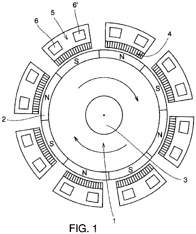
Fig.2 is a partial schematic view illustrating a magnetic array of the permanent magnet rotor and an arrangement of one of magnetically responsive coils placed around that rotor in an embodiment of the present invention.
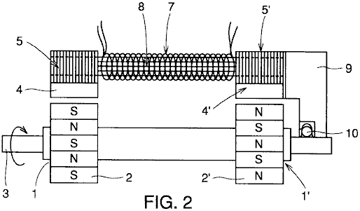
Fig.3 illustrates a structure of the magnetically responsive coils and cores in the embodiment of the present invention.

Fig.4 is an enlarged plan view of magnetically sensitive cores and coil portions of the load-free generator of the present invention illustrating magnetic flow therethrough.
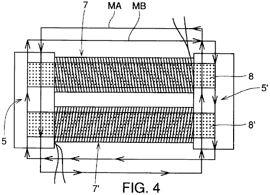
Fig.5 is an exploded view about a central axis showing the interconnection of magnetic field coils which are respectively wound around tertiary cores surrounding the permanent magnet rotor in FIG. 1 according to the present invention.
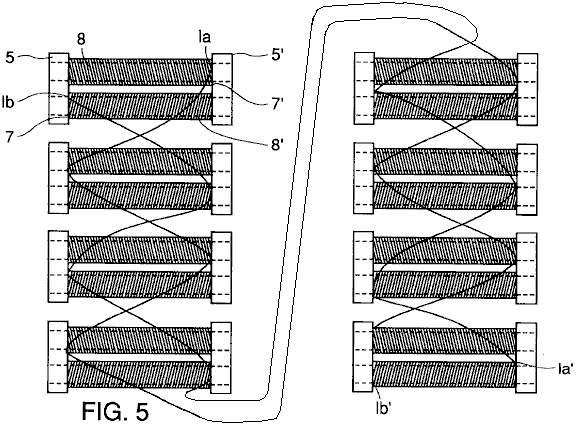
Fig.6 illustrates generation of the secondary load in a conventional generator.
BEST MODES FOR CARRYING OUT THE INVENTION
The structure and operation of a load-free generator according to the present invention are now described in conjunction with the drawings.
Fig.1 illustrates a cross sectional structure of the load-free generator of the invention perpendicular to a rotational axis 3.
Fig.2 partially illustrates a cross sectional structure of the load-free generator of the invention in parallel to rotational axis 3. Specifically, in Fig.2, only one of eight sets of magnetic induction primary cores 4 and 4' arranged around rotational axis 3 as described below is representatively shown.
Referring to Fig.1 and Fig.2, the structure of the load-free generator of the invention is now described. Permanent magnet trains 2 and 2' in ring forms are attached and fixed to respective left and right orbits 1 and 1' provided relative to rotational axis 3 with a certain interval between them. Permanent magnet trains 2 and 2' are fixed onto left and right orbits 1 and 1' respectively such that the polarities on the outer peripheral surface of each magnet train relative to the rotational axis are alternately N poles and S poles. The permanent magnet trains are rotatable about the axis. Further, the facing polarities of respective permanent magnet train 2 and permanent magnet train 2' relative to the direction of rotational axis 3 are arranged to be opposite.
As shown in Fig.2, rotational axis 3 and a case 9 are joined by a bearing 10 at a certain distance from the permanent magnet trains 2 and 2'.
At a predetermined distance from permanent magnet trains 2 and 2', magnetic induction primary cores 4 and 4' with respective coils wound around them are fixed to case 9.
In addition, magnetic induction secondary cores 5 and 5' each having two coupling holes 6 and 6' formed therein are structured by stacking and coupling a plurality of thin cores attached and fixed to magnetic induction primary cores 4 and 4' respectively and the secondary cores are attached and fixed to case 9.
Magnetic induction tertiary cores 8 and 8' are inserted respectively into coupling holes 6 and 6' of magnetic induction secondary cores 5 and 5' so as to couple magnetic induction secondary cores 5 and 5' of each other.
Responsive coils 7 and 7' are wound in opposite directions to each other around respective magnetic induction cores 8 and 8'.
Fig.3 illustrates a structure formed of magnetic induction secondary cores 5 and 5', magnetic induction cores 8 and 8' and responsive coils 7 and 7' viewed in the direction perpendicular to rotational axis 3.
As explained above, the directions of windings of responsive coils 7 and 7' are respectively opposite to each other around magnetic induction cores 8 and 8' which couple magnetic induction secondary cores 5 and 5'.
In the structure described in conjunction with Fig.1, Fig.2 and Fig.3, when rotational axis 3 of the generator rotates, permanent magnetic trains 2 and 2' accordingly rotate to generate magnetically sensitive currents (electromagnetically induced current) in responsive coils 7 and 7' and the current thus produced can be drawn out for use.
As shown in Fig.3, the coils are wound about magnetic induction cores 8 and 8' respectively in the opposite directions in the generator of the present invention, and the directions of the magnetic fields generated by the flow of the induced currents are arranged such that the N pole and S pole alternately occurs around rotational axis 3.
Fig.4 illustrates magnetic fields induced in a set of magnetic induction secondary cores 5 and 5', magnetic induction cores 8 and 8' and responsive coils 7 and 7'.
At iron strips on both ends of respective magnetic induction secondary cores 5 and 5', a reverse current magnetic field is generated by responsive coil 7 upon the rotation of N and S poles of permanent magnet trains 2 and 2' is in the direction of MA shown in Fig.4, for example, while a reverse current magnetic field generated by responsive coil 7 is in the direction of MB in Fig.4. Consequently, the reverse magnetic fields generated by the flow of currents cancel each other. The cores are formed of a plurality of iron strips in order to eliminate heat generated by eddy currents.
The magnetic field of the rotor thus has no dependence on the flow of currents, the load caused by the induced magnetisation phenomenon disappears, and energy of movement necessary for rotation against the mechanical primary load of the rotor itself is applied to the rotor.
At this time, a magnetic circuit including magnetic induction secondary cores 5 and 5' and magnetic induction tertiary cores 8 and 8' should be shaped into ".quadrature." form. If the circuit does not structured as ".quadrature." form, a part of the reverse magnetic field functions as electrical force which hinders the rotational force of the rotor.
Further, permanent magnet trains 2 and 2' of the rotor are arranged to have opposite poles to each other on the left and right sides as shown in Fig.2 so as to constitute the flow of magnetic flux. Each rotor has alternately arranged magnets, for example, eight poles are provided to enhance the generator efficiency.
More detailed description of the operational principle is given now. When the rotor in Fig.1 rotates once, S and N poles of permanent magnets 2 and 2' attached to the periphery of the rotor successively supply magnetic fields to induction primary cores 4 above, and magnetic field is accordingly generated in a path from one orbit of the rotor along induction primary core 4, induction secondary core 5, induction tertiary core 8, induction secondary core 5', induction primary core 4' to the other orbit of the rotor as shown in Fig.2.
Accordingly, current flows in the coils affected by this electric field to generate electric power. For example, if the generated power is used as generated output for switching on an electric light or for using it as motive energy, the current flowing through the coils generates the reverse magnetic fields. However, this reverse magnetic fields do not influence permanent magnets 2 and 2' attached to the rotor in Fig.2 since the reverse magnetic fields of the same magnitude respectively of S and N or N and S on both ends of magnetic induction secondary cores 5 and 5' cancel out each other as shown in Fig.4. Because of this, the rotor is in a no-load state in which any resistance except the weight of the rotor itself and dynamic resistance is not exerted on the rotor.
Fig.5 illustrates a manner of connecting magnetically responsive coils 7 and 7' wound around magnetic induction tertiary cores 8 and 8' with eight poles.
Referring to Fig.5, according to a method of connecting magnetically responsive coils 7 and 7' , line 1a1 of responsive coil 7' (one drawn-out line of the wire coiled around a first magnetic induction core 8) is connected to line 1a2' (one drawn-out line of the wire coiled around a second magnetic induction core 8), and then line 1a2 (the other drawn-out line of the wire coiled around a second magnetic induction core 8) is connected to line 1a3', and subsequently lines 1a and 1a' are connected successively in zigzag manner to allow current to flow. Further, responsive coil 7 is arranged to connect lines represented by 1b1 in zigzag manner such that lines 1b and 1b' are successively connected. In this way, lines 1b, 1b' and lines 1a and 1a' of respective magnetically responsive coils 7 and 7' are connected. As a whole, total four electric wires are drawn out for use.
When electric power is to be generated according to the present invention as described above, specifically, a closed circuit is formed by responsive coils 7 and 7', electric currents are induced in responsive coils 7 and 7' wound around the magnetic induction cores of the generator, and the induced magnetic fields produced respectively by responsive coils 7 and 7' could cause a great load which interferes the rotational force of the rotor. However, as shown in Fig.4, the direction of convolution of one coil 7 is opposite to that of the other coil 7' so that the magnetic force generated by the reverse currents (induced currents) in responsive coils 7 and 7' wound around magnetic induction core 4 is not transmitted to magnetic induction cores 8 and 8 accordingly no reverse magnetic force is transmitted to permanent magnets 2 and 2'.
Therefore, each time the N poles and S poles alternate with each other because of the alternation of permanent magnets 2 and 2' shown in Fig.2, the reverse magnetic forces in the right and left direction opposite to the direction of arrows denoted by MA and MB completely disappear as shown in Fig.4. Consequently, the reverse magnetic forces caused by the reverse currents are not influenced by permanent magnets 2 and 2' and accordingly no load except the mechanical primary load is exerted on the generator of the invention.
As discussed above, the load-free generator of the present invention, secondary load except mechanical load of the generator, i.e. the load caused by the reverse currents flowing through the responsive coils can be nulled. With regard to this load-free generator, even if 100% of the current generated by magnetic induction (electromagnetic induction) is used, the magnetic secondary load due to the reverse currents except the mechanical primary load does not serve as load.
Although the number of poles of the rotor is described as 8 in the above description, the present invention is not limited to such a structure, and the invention can exhibit its effect when the smaller or greater number of poles is applied.
Further, although the magnet of the rotor is described as the permanent magnet in the above structure, the invention is not limited to such a case and the magnet of the rotor may be an electromagnet, for example.
In addition, although the description above is applied to the structure of the rotating-field type generator, the generator may be of the rotating-armature type.
EXPERIMENTAL
EXAMPLE
More detailed description of the generator of the present invention is hereinafter given based on specific experimental examples of the invention.
The generator of the present invention and a conventional generator were used to measure the electric power production efficiency and the amount of load and compare the resultant measurements.
EXPERIMENTAL EXAMPLE 1
A 12-pole alternating current (AC) generator for battery charging was used, and the electricity output and the load when 50% of the electricity output was used as well as those when 100% of the electricity output was used were measured. The generator above is a single-phase AC motor and the employed power source was 220V, with 1750 rpm and the efficiency of 60%. The result of measurement using power of a motor of 0.5HP and ampere .times.volt gauge is shown in Table 1.
EXPERIMENTAL EXAMPLE 2
Measurement was done under the same conditions as those of experimental example 1 and a generator used was the one which was made according to the present invention to have the same conditions as those of the product of the existing model above. The result of measurement using ampere x volt gauge is shown in Table 1.
Table 1
|
|
50% Electricity |
Used |
100% Electricity |
Used |
|
Type of Generator |
Electricity Output ( |
Amount of Load ( |
Electricity Output ( |
Amount of Load ( |
|
Conventional: |
100 |
221 |
14 |
347 |
|
This invention: |
100 |
220 |
183 |
200 |
(electricity output and load amount of the alternating current generators when 50% and 100% of the electricity were used)
From the result of Experimental Example 1 above, the reason for the remarkable reduction of the electricity output when the electricity consumption was 100% relative to the electricity consumption of 50% in the conventional generator is considered to be the significant increase of the repulsive load exerted on the generator when 100% of the electricity is used.
On the other hand, in the generator of the present invention, there was no appreciable difference in the amount of load between those cases in which 50% of the electricity was used and 100% thereof was used respectively. Rather, the amount of load slightly decreased (approximately 20W) when 100% of the electricity was used. In view of this, it can be understood that the amount of generated electric power of the generator of the present invention is approximately doubled as the electricity consumption increases, which is different from the conventional generator producing electric power which sharply decreases when the electricity consumption increases.
In conclusion, the amount of load above is supposed to be numerical value relative to the mechanical load of the generator as described above. Any secondary load except this, i.e. load due to the reverse currents generated in the armature responsive coils can be confirmed as zero.
EXPERIMENTAL EXAMPLE 3
12V direct current (DC) generators having similar conditions to those in experimental example 1 were used to make measurement under the same conditions (efficiency 80%). The result of the measurement is presented below.
Table 2
|
|
50% Electricity |
Used |
100% Electricity |
Used |
|
Type of Generator |
Electricity Output ( |
Amount of Load ( |
Electricity Output ( |
Amount of Load ( |
|
Conventional: |
103 |
290 |
21 |
298 |
|
This invention: |
107 |
282 |
236 |
272 |
(electricity output and load amount of the alternating current generators when 50% and 100% of the electricity were used)
The DC generator has higher efficiency (80%) than that of the AC generator, while use of the brush increases the cost of the DC generator. When 100% of the electricity was used, the amount of load slightly decreased which was similar to the result shown in Table 1 and the electricity output was approximately at least 2.2 times that when 50% of the electricity was used.
EXPERIMENTAL EXAMPLE 4
A 220V single-phase alternating current (AC) generator (0.5HP) having similar conditions to those in experimental example 1 was used, and the rotation per minute (rpm) was changed to make measurement under the condition of 100% consumption of the generated electricity. The result of measurement is illustrated in the following Table 3.
Table 3
|
1750 |
rpm |
3600 |
rpm |
5100 |
rpm |
|
Electricity Output ( |
Amount of Load ( |
Electricity Output ( |
Amount of Load ( |
Electricity Output ( |
Amount of Load ( |
|
130 |
160 |
210 |
228 |
307 |
342 |
(amounts of generated electric power and load when the rotation per minute of the generator of the present invention was varied)
As shown in Table 3 above, as the rotation per minute (rpm) increases as from 1750, 3600 to 5100, the amount of electric power increases respectively from 130, 210 to 307W and consequently the difference between the amount of generated electric power and the amount of load decreases to cause relative decrease of the amount of load as the rotation per minute (rpm) increases.
EXPERIMENTAL EXAMPLE 5
Measurement was done by changing the number of N and S poles of the permanent magnets of the invention under the same conditions as those of experimental example 1 and under the condition that 100% of the generated electricity was used.
The result of the measurement is illustrated below.
Table 4
|
2 |
poles |
4 |
poles |
8 |
poles |
|
Electricity Output ( |
Amount of Load ( |
Electricity Output ( |
Amount of Load ( |
Electricity Output ( |
Amount of Load ( |
|
80 |
152 |
130 |
200 |
265 |
296 |
(amounts of generated electric power and load when the number of poles of the permanent magnets of the generator of the invention was changed)
From Table 4 above, it can be understood that as the number of poles increases, both of the amounts of generated electric power and load increase. However, the ratio of the amount of generated electric power to the amount of load monotonously increases. In the table above, in terms of the amount of load, only the mechanical primary load is exerted and electrical secondary is not exerted.
The increase of the number of poles causes increase, by the number of increased poles, in the number of lines of magnetic flux which coils traverse, and accordingly the electromotive force increases to increase the amount of generated electric power. On the other hand, the amount of mechanical load has a constant value regardless of the increase of the number of poles, so that the mechanical load amount relatively decreases to reduce the difference between the amount of load and the amount of generated electric power.
Detailed description of the present invention which has been given above is just for the purpose of presenting example and illustration, not for limitation. It will dearly be appreciated that the spirit and scope of the invention will be limited only by the attached scope of claims.
ALBERTO MOLINA-MARTINEZ: ELECTRICAL GENERATOR
Patent Application US 20020125774
6th March 2002 Inventor:
Alberto Molina-Martinez
CONTINUOUS ELECTRICAL GENERATOR
This patent application shows the details of a device which it is claimed, can produce sufficient electricity to power both itself and external loads. It also has no moving parts.
ABSTRACT
A stationary cylindrical electromagnetic core, made of one piece thin laminations stacked to desired height, having closed slots radially distributed, where two three-phase winding arrangements are placed together in the same slots, one to the centre, one to the exterior, for the purpose of creating a rotational electromagnetic field by temporarily applying a three-phase current to one of the windings, and by this means, inducting a voltage on the second one, in such a way that the outgoing energy is a lot greater than the input. A return will feedback the system and the temporary source is then disconnected. The generator will run by itself indefinitely, permanently generating a great excess of energy.
BACKGROUND OF THE INVENTION
1. Field of the Invention
The present invention relates generally to electrical power generating systems. More specifically, the present invention relates to self-feeding electrical power generating units.
2. Description of Related Art
Since Nikola Tesla invented and patented his Polyphase System for Generators, Induction Motors and Transformers, no essential improvement has been made in the field. The generators would produce the polyphase voltages and currents by means of mechanical rotational movement in order to force a magnetic field to rotate across the generator's radially spaced windings. The basis of the induction motor system was to create an electro-magnetically rotating field, instead of a mechanically rotated magnetic field, which would induce voltages and currents to generate electromotive forces usable as mechanical energy or power. Finally, the transformers would manipulate the voltages and currents to make them feasible for their use and transmission for long distances.
In all present Electric Generators a small amount of energy, normally less than one percent of the outgoing power in big generators, is used to excite the mechanically rotated electromagnetic poles that will induce voltages and currents in conductors having a relative speed or movement between them and the polar masses.
The rest of the energy used in the process of obtaining electricity, is needed to move the masses and to overcome the losses of the system: mechanical losses; friction losses; brushes losses, windage losses; armature reaction losses; air gap losses; synchronous reactance losses; eddy current losses; hysteresis losses, all of which, in conjunction, are responsible for the excess in power input (mechanical power) required to generate always smaller amounts of electric power.
SUMMARY OF THE INVENTION
The Continuous Electrical Generator consists of a stationary cylindrical electromagnetic core made of one piece thin laminations stacked together to form a cylinder, where two three-phase windings arrangements are placed in the same slots not having any physical relative speed or displacement between them. When one of the windings is connected to a temporary three-phase source, an electromagnetic rotating field is created, and the field this way created will cut the stationary coils of the second winding, inducting voltages and currents. In the same way and extent as in common generators, about one percent or less of the outgoing power will be needed to keep the rotational magnetic field excited.
In the Continuous Electrical Generator there are no mechanical losses; friction losses; brush losses; windage losses; armature reaction losses; or air gap losses, because there is not any movement of any kind. There are: synchronous reactance losses, eddy current losses and hysteresis losses, which are inherent to the design, construction and the materials of the generator, but in the same extent as in common generators.
One percent or less of the total energy produced by present electric generators goes to create their own magnetic field; a mechanical energy that exceeds the total output of present generators is used to make them rotate in the process of extracting electrical currents from them. In the Continuous Electrical Generator there is no need for movement since the field is in fact already rotating electro-magnetically, so all that mechanical energy will not be needed. Under similar conditions of exciting currents, core mass and windings design, the Continuous Electrical Generator is significantly more efficient than present generators, which also means that it can produce significantly more than the energy it needs to operate. The Continuous Electrical Generator can feedback the system, the temporary source may be disconnected and the Generator will run indefinitely.
As with any other generator, the Continuous Electrical Generator may excite its own electromagnetic field with a minimum part of the electrical energy produced. The Continuous Electrical Generator only needs to be started up by connecting its inducting three-phase windings to a three-phase external source for an instant, and then to be disconnected, to start the system as described herein. Then, disconnected, it will run indefinitely generating a great excess of electric power to the extent of its design.
The Continuous Electrical Generator can be designed and calculated with all mathematical formulas in use today to design and calculate electrical generators and motors. It complies with all of the laws and parameters used to calculate electrical induction and generation of electricity today.
Except for the Law of Conservation of Energy, which, by itself, is not a mathematical equation but a theoretical concept and by the same reason does not have any role in the mathematical calculation of an electrical generator of any type, the Continuous Electrical Generator complies with all the Laws of Physics and Electrical Engineering. The Continuous Electrical Generator obligates us to review the Law of Conservation of Energy. In my personal belief, the electricity has never come from the mechanical energy that we put into a machine to move the masses against all oppositions. The mechanical system is actually providing the path for the condensation of electricity. The Continuous Electrical Generator provides a more efficient path for the electricity.
DESCRIPTION
OF DRAWINGS
Fig.1 shows one embodiment of the present invention.
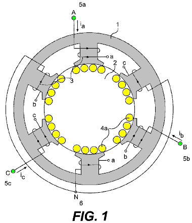
Fig.2 shows an internal wiring diagram for the embodiment of the present invention shown in Fig.1.
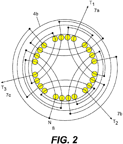
Fig.3 shows a single laminate for an alternate embodiment of the present invention.

Fig.4 shows a two-piece single laminate for another alternate embodiment of the present invention.
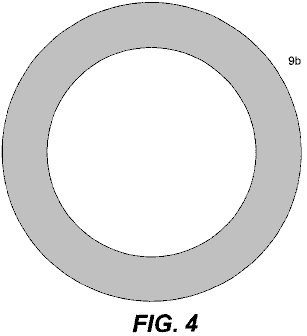
Fig.5 shows a wiring diagram for an embodiment of the present invention constructed from the laminate shown in Fig.3 or Fig.4.
Fig.6 shows the magnetic flux pattern produced by the present invention.

Fig.7 shows the rotational magnetic field patterns produced by the present invention.
Fig.8 shows the complete system of the present invention.
Fig.9 is an expanded view of the alternate embodiment of the present invention shown in Fig.3 or Fig.4.
DETAILED
DESCRIPTION OF THE INVENTION
The present invention is a Continuous and Autonomous Electrical Generator, capable of producing more energy than it needs to operate, and which provides itself the energy needed to operate. The basic idea consists in the induction of electric voltages and currents without any physical movement by the use of a rotational magnetic field created by a three-phase stator connected temporarily to a three-phase source, and placing stationary conductors on the path of said rotational magnetic field, eliminating the need of mechanical forces.
The basic system can be observed in Fig.1, which shows one embodiment of the present invention. There is a stationary ferromagnetic core 1 with a three-phase inducting windings 3, spaced 120 degrees and connected in Y 6 in order to provide a rotating electromagnetic field, when a three-phase voltage is applied; for the case, a two-pole arrangement. Inside this core 1 there is a second stationary ferromagnetic core 2, with no space between them, this is, with no air-gap. This second core 2 has also a three-phase stationary winding arrangement (4a in Fig.4b and 4b in Fig.2), aligned as shown in Fig.1 and Fig.2 with the external core inducting windings 3. There is not any movement between the two cores, since there is no air-gap between them.
There is no shaft on either core since these are not rotating cores. The two cores can be made of stacked insulated laminations or of insulated compressed and bonded ferromagnetic powder. The system works either way, inducting three-phase voltages and currents on the stationary conductors 4a of the internal windings 4b, applying three-phase currents to terminals A 5a, B 5b and C 5c of the external windings 3; or inducting three-phase voltages and currents on the external windings 3, by applying three-phase currents to the terminals T1 7a, T2 7b and T3 7c, of the internal windings 4b. When a three-phase voltage is applied to terminals A 5a, B 5b and C 5c, the currents will have the same magnitude, but will be displaced in time by an angle of 120 degrees. These currents produce magneto motive-forces, which, in turn, create a rotational magnetic flux. The arrangements may vary widely as they occur with present alternators and three-phase motors, but the basics remain the same, a stationary but electro-magnetically rotating magnetic field, inducting voltages and currents on the stationary conductors placed on the path of said rotating magnetic field. The diagram is showing a two-pole arrangement for both windings, but many other arrangements may be used, as in common generators and motors.
Fig.2 shows the three-phase arrangement of the internal winding 4b which has provided, in practice, symmetrical voltages and currents, due to a space angle of 120 degrees. It is similar to a two-pole arrangement. Many other three-phase or poly-phase arrangements may be used. Wherever a conductor is crossed by a rotational magnetic field, a voltage will be induced across its terminals. The interconnections depend on the use that we will give to the system. In this case, we will have a three-phase voltage in terminals T1 7a, T2 7b and T3 7c and a neutral 8. The outgoing voltage depends on the density of the rotational magnetic flux, the number of turns of the conductor, the frequency (instead of the speed) and the length of the conductor crossed by the field, as in any other generator.
Fig.3 shows an alternate embodiment of the present invention in which the generator is made from multiple one-piece laminations 9, stacked as a cylinder to the desired height. This embodiment can also be made of a one-piece block of compressed and bonded insulated ferromagnetic powder. The same slot 10 will accommodate the internal 4a/4b and the external windings 3, that is, the inducting and the induced windings (see Fig.5). In this case, a 24-slot laminate is shown, but the number of slots may vary widely according to the design and needs.
Fig.4 shows a two-piece single laminate for another alternate embodiment of the present invention. For practical effects the lamination can be divided into two pieces 9a, 9b, as shown, to facilitate the insertion of the coils. Then, they are solidly assembled without separation between them, as if they were only one piece.
The laminates described above may be constructed with thin (0.15 mm thick or less) insulated laminations 9 or 9a and 9b of a high magnetic permeability material and low hysteresis losses such as Hiperco 50A, or similar, to reduce losses or with compressed electrically isolated ferromagnetic powder, which has lower eddy current losses and also may have low hysteresis losses, which can make the generator highly efficient.
OPERATING THE GENERATOR
The Continuous Electrical Generator as described and shown in the following drawings is designed and calculated to produce a strong rotating electromagnetic field with low exciting currents. By using a laminated material, such as the said Hiperco 50A, we can achieve rotating magnetic fields above two Teslas, since there are no air gap losses, mechanical losses, windage losses, armature reaction losses, etc. as said before. This may be obtained by applying a temporary three-phase current to the terminals A, B and C 12 of the inducting coils 13, 14 and 15 (5a, 5b and 5c in Fig.1), spaced 120 degrees from each other (see Fig.5).
Fig.5 shows the spatial distribution of the inducting windings 13, 14 and 15, as well as the induced windings 18a, 18b, 19a, 19b, 20a and 20b. Both, the inducting and the induced windings are placed in the same slots 10 or 16 and 17, with similar arrangements. Even though the system works in both directions, the better configuration seems to be to place the inducting windings 13, 14 and 15, to the centre and the induced windings 18a, 18b, 19a, 19b, 20a and 20b, to the exterior, since small windings will be needed to induce a very strong rotational magnetic field, due to the small losses involved in the process, and in exchange, bigger and powerful windings will be needed to extract all the energy that the system will provide. Both windings are connected in Y (not shown), but they can be connected in different ways, as any other generator. These arrangements are equivalent to the arrangements shown for the embodiment in Fig.1 and Fig.2.
The inducting coils 13, 14 and 15 are designed and calculated so that the generator may be started with common three-phase lines voltages (230 Volts 60 Hz per phase, for example). If the local lines voltages are not appropriate, we can control the voltage to the designed level by means of a three-phase variable transformer, an electronic variator or inverter etc. Once we have such strong magnetic field rotating and crossing the stationary induced coils 18a, 18b, 19a, 19b, 20a and 20b, a three-phase voltage will be induced across terminals T1, T2, T3 and N 21 in proportion to the magnetic flux density, the number of turns in the coils, the frequency used (instead of the speed), the length of the conductors cut by the rotating field, as in any other alternator. We can connect, as we desire in Y or delta, etc., as in any other alternator or generator. The outgoing currents will be three-phase currents (or poly-phase currents depending on the arrangement) and we can have a neutral 21 if we are using a Y connection, as in any other alternator.
The outgoing alternate voltages and currents are perfect sinusoidal waves, perfectly spaced in time, and totally symmetrical. The voltages and currents obtained by this method are usable in any conventional manner. Any voltage can be produced, depending on the design.
Fig.6 shows the magnetic flux pattern produced by the three-phase inducting windings 13, 14 and 15. This pattern is similar to the pattern of an induction motor's stators. Since there is no air gap; the whole path for the magnetic flux is homogeneous with no change in materials. The core is made of thin insulated laminations of a high magnetic permeability and low hysteresis loss material; eddy current losses are minimal due to the thin lamination. There are no counter fluxes or armature reactions thus the magnetic flux may be near to saturation with a small exciting current or input energy. Due to the time differential between the three phases and the spatial distribution of the inducting windings, a rotational magnetic field will be created in the core, as shown in Fig.7.
Once the generator is started, a small part of the energy obtained is sent back (Fig.8 and Fig.9) to feed the inducting coils 3 (in Fig.1) or 13, 14 and 15 (in Fig.5), as in any other auto-excited alternator or generator. Of course voltages and phases should be perfectly identical and aligned, and if necessary the feedback voltages should be controlled and handled by means of variable transformers, electronic variators, phase shifters (to align phases) or other type of voltage or phase controllers.
One possible method consists of the use of an electronic converter or variator 25 which initially converts two or three lines of alternating current 24 to direct current by an electronic rectifier 26 and then, electronically, converts the direct current 27 to three-phase current 28 to supply three-phase currents spaced in time 120 degrees for the electromagnetic fields A, B and C 3. Some variators or converters can accept two lines of voltage, while others will accept only a three-phase line voltage. This embodiment uses a variator of 3 kVA that accepts two 220-volt lines.
The rotational magnetic field created by the currents going through the inducting three-phase windings 13, 14 and 15, will induce a voltage across the terminals T1, T2, T3, N, 29 (7a, 7b, 7c, 8 in Fig.2). Then, from the outgoing current lines 29, a derivation is made 30 to feed back the system, converting the feed back alternate currents, by means of electronic diode rectifiers 31, to direct current 32 and then feed back the electronic converter or variator 25 to the DC terminals of the electronic rectifier 26 (See Fig.8). Once the feedback is connected, the Continuous Electrical Generator may be disconnected from the temporary source 24, and will continue generating electric energy indefinitely.
In Fig.9, an alternate embodiment of the Continuous Electrical Generator can be observed. The basic principles remain the same as for the embodiment described above and shown in Fig.1 and Fig.2. The basic differences are in the shape of the laminations and the physical distribution of the windings, as discussed and shown previously. A variation of the feedback, using a variable and shifting transformers is also shown.
The ferromagnetic core 11 is made of one-piece laminates 9 as shown in Fig.3 (or two for convenience 9a, 9b as shown in Fig.4) stacked to the desired height. The slots 10, as indicated before, will accommodate both the inducting 13, 14 and 15 and the induced 18a-b, 19a-b and 20a-b windings in the same slot 10 or 16 and 17. The incoming three phase lines 12 feed the inducting three-phase windings 13, 14 and 15. They are fed, initially by the temporary source 33 in the first instance, and by the three-phase return 34 once the generator is running by itself.
The inducting windings 13, 14 and 15 have a two-pole arrangement, but many other three-phase or poly-phase arrangements can be made to obtain an electromagnetic rotating field. These windings are connected in Y (not shown) in the same way shown for the embodiment shown in Fig.1, Fig.2 and Fig.8, but may be connected in many different ways. The inducting windings 13, 14 and 15 are located in the internal portion 16 of the slot 10 (Fig.5).
The induced windings 18a-b, 19a-b and 20a-b have a two-pole arrangement, exactly equal to the arrangement for the inducting windings 13, 14 and 15, but many other arrangements can be made depending on the design and the needs. The induced windings must be calculated in a way that the generator will have the lowest possible synchronous reactance and resistance. In this way, most of the outgoing power will go to the charge instead of staying to overcome the internal impedance. These windings are connected in Y to generate a neutral 21, in the same way shown in the embodiment of the present invention shown in Fig.2, but may be connected in different ways according to the needs. The induced windings 18a-b, 19a-b and 20a-b are located in the external portion 17 of the slot 10.
The outgoing three-phase and neutral lines 21 come from the induced windings 18a-b, 19a-b and 20a-b. The rotational magnetic field created in the core (see Fig.6 & Fig.7) by the inducting windings 13, 14 and 15, induces a voltage across the terminals T1, T2 and T3, plus a neutral, 29. From each of the three-phase outgoing lines 21, a return derivation 34 is made to feedback the system.
The temporary three-phase source 33 is temporarily connected to terminals A, B and C 12. The Continuous Electrical Generator must be started with an external three-phase source for an instant, and then disconnected.
Even though the return lines voltage can be calculated and obtained precisely by tabbing the induced windings at the voltage required by the inducting windings (according to the design), it may be convenient to place a three-phase variable transformer or other type of voltage controller 35 in the middle for more precise adjustment of the return voltage.
Placed after the variable transformer 35, the three-phase shifting transformer 36 will correct and align any phase shift in the voltage and currents angles, before the return is connected. This system functions similarly to the system shown in Fig.8 which uses a variator or a converter 25.
Once the voltage and phases are aligned with the temporary source 33, the return lines 34 are connected to the incoming lines A, B and C 12 at feedback connection 37 and the temporary source 33 is then disconnected. The Continuous Electrical Generator will remain working indefinitely without any external source of energy, providing a great excess of energy permanently.
The outgoing electric energy provided by this system has been used to produce light and heat, run poly-phase motors, generate usable mono-phase and poly-phase voltages and currents, transform voltages and currents by means of transformers, convert the alternate outgoing poly-phase currents to direct current, as well as for other uses. The electricity obtained by the means described is as versatile and perfect as the electricity obtained today with common electric generators. But the Continuous Electrical Generator is autonomous and does not depend on any other source of energy but itself once it is running; may be carried anywhere with no limitations; it can be constructed in any size and provides any amount of electricity indefinitely, according to the design.
The Continuous Electrical Generator is and will be a very simple machine. The keystones of the systems reside in the ultra-low losses of a non-movement generation system, and in a very low synchronous reactance design.
The induced windings must be calculated in a way that the generator may have the lowest possible synchronous reactance and resistance. In this way, most of the outgoing power will go to the charge instead of staying to overcome the internal impedance.
MICHAEL OGNYANOV: SEMICONDUCTORS
Patent Application US 3,766,094
20th September 1971
Inventor: Michael Ognyanov
SEMICONDUCTOR COMPOSITIONS
This patent application shows the details of a device which it is claimed, can produce electricity via a solid-state oscillator. It should be noted that while construction details are provided which imply that the inventor constructed and tested several of these devices, this is only an application and not a granted patent.
ABSTRACT
A resonance oscillator electric power pack for operating a flash lamp, for example, or other electrically operated device, operates without moving mechanical parts or electrolytic action. The power pack is contained in a cylindrical metal envelope and in a preferred embodiment, is coupled to a relaxation oscillator and an incandescent lamp. Within the envelope, and insulated from it, is a semiconductor tablet having a metal base connected to the external circuit. A metal probe makes contact with a point on the semiconductor tablet and with a cylindrical ferrite rod, axially aligned with the envelope. Wound about the ferrite rod, are concentric helical coils designated as a ‘primary’ with many turns, and a ‘secondary’ with fewer turns than the primary.
One end of the primary coil is connected to the probe and the other end is connected to the secondary coil. the leads from the secondary coil are connected to the relaxation oscillator via an adjustable capacitor. Oscillation within the envelope is resonance amplified , and the induced voltage in the secondary coil is rectified for application to the relaxation oscillator and lamp. Selenium and germanium base semiconductor compositions including Te, Nd, Rb and Ga in varying proportions area used for the tablet.
BACKGROUND OF THE INVENTION
This is a continuation-in-part of my co-pending patent application Serial No. 77,452, filed 2nd October 1970, entitled “Electric Power Pack” now abandoned.
In many situations it is desirable to have a source of electric power which is not dependent on wires from a central generating station, and therefore, portable power supplies having no moving parts have been employed. typically, such portable power packs have been primary or secondary electrolytic cells which generate or store electrical energy for release by chemical action. Such batteries have a limited amount of contained energy and must often be replaced at frequent intervals to maintain equipment in operation.
Thus, as one example, flashing lights are commonly used along highways and other locations to warn of dangerous conditions. These flashing lights in remote locations are typically incandescent or gas-discharge lamps connected to some type of relaxation oscillator powered by a battery. The batteries employed in such blinking lights have a limited lifetime and must be periodically replaced, typically each 250 to 300 hours of operation. This involves a rather large labour cost in replacing the expended batteries with fresh ones and additional cost for primary cells or for recharging secondary cells. It is desirable to provide an electric power pack capable of providing a sufficient quantity of electrical energy over a prolonged period of time so that the requirement for periodic replacement of the electrolytic cells can be avoided. Such a power pack is valuable even if appreciably more expensive than batteries because of the greatly reduced labour costs required for periodic replacements.
BRIEF SUMMARY OF THE INVENTION
There is provided in practice of this invention according to a preferred embodiment, semiconductive compositions selected from the Group consisting of:
Selenium with, from 4.85% to 5.5% Tellurium, from 3.95% to 4.2% Germanium, from 2.85% to 3.2% Neodymium, and from 2.0% to 2.5% Gallium.
Selenium with, from 4.8% to 5.5% Tellurium, from 3.9% to 4.5% Germanium, from 2.9% to 3.5% Neodymium and from 4.5% to 5% Rubidium, and
Germanium with, from 4.75% to 5.5% Tellurium, from 4.0% to 4.5% Neodymium and from 5.5% to 7.0% Rubidium.
DRAWINGS
These and other features and advantages of the invention will be appreciated and better understood by reference to the following detailed description of a preferred embodiment when considered in conjunction with the following drawings:
Fig.1 illustrates in exploded schematic, a flashing lamp connected to an electric power supply constructed according to the principles of this invention.
Fig.2 illustrates in longitudinal cross-section, the power pack of Fig.1
Fig.3 is an electric circuit diagram of the system.
DESCRIPTION
Fig.1 illustrates schematically, a typical flashing lamp having a power supply constructed according to the principles of this invention. As illustrated in this preferred embodiment, an electric power pack 5, is connected electrically to a relaxation oscillator circuit (shown only schematically) on a conventional printed-circuit board 6.
The power pack
5 and the printed-circuit board are
mounted in a metal
A cover 9, having mounting lugs 10, is riveted on to the box after
assembly. A small terminal strip 11, mounted on one side of the
In Fig.2, the electric power pack 10, is illustrated in longitudinal cross-section and has dimensions as follows: These dimensions are provided by way of example for powering a conventional flashing lamp and it will be clear that other dimensions may be used for other applications. In particular, the dimensions may be enlarged in order to obtain higher power levels and different voltage or current levels. The power pack is comprised of a cylindrical metal tube 16, having closely fitting metal caps 17 at each end, which are preferably sealed to the tube after the internal elements are inserted in place. The metal tube 16 and caps 17, which are preferably of aluminium, thus form a closed conductive envelope, which in a typical embodiment, has an inside diameter of about 0.8 inch and a length of about 2.25 inches.
Mounted within one end of the envelope is a plastic cup 18, the dimensions of which are not critical, however, a wall thickness of at least 1/16 inch is preferred. Mounted within the plastic cup 18 is a semiconductor tablet 19 having a flat base and somewhat domed opposite side. The composition of the semiconductor tablet 19 is set out in greater detail below. Typically, the semiconductor tablet has a mass of about 3.8 grams. A metal disc 21 is positioned beneath the base of the tablet 19 in the cup 18, and is preferably adhesively bonded inside the cup. The metal disc is tightly fitted to the base of the tablet so that good electrical contact is obtained over a substantial area of the semiconductor.
An ear 22 on one edge of the disc is soldered to a wire 23, which extends through a short insulating sleeve 24 which passes through a hole in the side of the metal envelope. The insulating sleeve 24 acts as a grommet and ensures that there is no damage to the insulation of wire 23 and subsequent accidental short circuiting between the wire and the metal envelope. Preferably, the insulating sleeve 24 is sealed with a small amount of plastic cement or the like, in order to maintain clean air within the cylindrical envelope. Two other openings for leads through the tube 16, as mentioned below, are also preferably sealed to maintain cleanliness within the envelope.
A pair of circular metal discs 26, are fitted inside tube 16 and are preferably cemented in place to prevent shifting. The two discs 26, are equally spaced from the opposite ends of the envelope and are spaced apart by slightly more than 1.15 inches. Each of the discs has a central aperture 27, and there is a plurality of holes 28, extending through the disc in a circular array midway between the centre of the disc and it’s periphery. The holes 28 are preferably in the size range of about 0.01 to 0.06 inch in diameter and there are 12 on each disc located at 300 intervals around the circle.
The two discs 26 divide the interior of the cylindrical envelope into three chambers, and the pattern of holes 28 provides communication between the chambers and affects the electrical properties of the cavity. It is believed that the pattern of holes affects the inductive coupling between the cavities inside the envelope and influences the oscillations in them.
Although an arrangement of 12 holes at 300 centres has been found particularly advantageous in the illustrated embodiment, it is found in other arrangements that a pattern of 20 holes at 180 centres or a pattern of 8 holes at 450 centres, provides optimum operation. In either case, the circle of holes 28 is midway between the centre and the periphery of the disc.
Mounted between the discs 26 is a plastic spool 29 which has an inside distance of 1.1 inches between its flanges. The plastic spool 29 preferably has relatively thin walls and an internal bore diameter of 1/8 inch. A plastic mounting plug 31, is inserted through the central aperture 27 of the disc 26 farthest from the semiconductor table 19, and into the bore of the spool 29. The plastic plug 31 is preferably cemented to the disc 26 in order to hold the assembly together.
Also mounted inside the bore of spool 29 is a cylindrical ferrite core 32, about 1/8 inch diameter and 3/4 inch long. Although a core of any magnetic ferrite is preferred, other ferromagnetic materials having similar properties can be used if desired. The core 32, is in electrical contact with a metal probe 33 about 1/4 inch long. half of the length of the probe 33 is in the form of a cylinder positioned within the spool 29, and the other half is in the form of a cone ending in a point 34 in contact with the domed surface of the semiconductor tablet 19 where it makes an electrical contact with the semiconductor in a relatively small point.
Electrical contact is also made with the probe 33 by a lead 36, which passes through one of the holes 28 in the disc 26 nearer to the semiconductor tablet and thence to a primary coil 37, wound on the plastic spool 29. The primary coil 37 is in the form of 800 to 1000 turns wound along the length of the spool, and the lead 38 at the opposite end of the coil 37 is soldered to one of the external leads 39 of the power pack. This lead 39 proceeds through one of the holes 28 in the disc farthest from the semiconductor tablet 19, and through an insulating sleeve 41 in the metal tube 16.
The lead 39 is also connected to one end of a secondary coil 42 which is composed of 8 to 10 turns around the centre portion of the primary coil 37. A thin insulating sheet 43 is provided between the primary and secondary coils. The other lead 44 from the secondary coil passes through one of the holes 28 in the disk nearer the semiconductor tablet and thence through an insulating sleeve 46 through the wall of the tube 16.
Fig.3 illustrates schematically, the electrical circuit employing an electric power pack constructed according to the principles of this invention. At the left hand side of Fig.3, the arrangement of elements is illustrated in a combination of electrical schematic and mechanical position inside tube 16 for ready correlation with the embodiment illustrated in Fig.2. Thus, the semiconductor tablet 19, probe 33 and ferrite core 32 are shown in both their mechanical and electrical arrangement, the core being inductively coupled to the coils 37 and 42. The lead 23 from the metal base of the semiconductor tablet 19, is connected to a variable capacitor 47, the other side of which is connected to the lead 44 from the secondary coil 42. The lead 44 is also connected to a rectifying diode 48 shunted by a high value resistor 49.
It will be seen that the variable capacitor 47 is in a tank circuit with the inductive coils 37 and 42 which are coupled by the ferrite core 32, and this circuit also includes the semiconductor tablet 19 to which point contact is made by the probe 33. The mechanical and electrical arrangement of these elements provides a resonant cavity in which resonance occurs when the capacitor 47 is properly trimmed. The diode 48, rectifies the oscillations in this circuit to provide a suitable DC for operating an incandescent lamp 50 or similar load.
The rectifying diode 48 is connected to a complementary-symmetry relaxation circuit for switching power to the load 50. The diode is connected directly to the collector of a PNP transistor 51 which is in an inverted connection. the emitter of the PNP transistor is connected to one side of the load 50 by way of a timing resistor 55. The base of the transistor 51 is connected by way of a resistor 52 and a capacitor 56 to the collector of an NPN transistor 53, the emitter of which is connected to the other side of the load 50. The base of the NPN transistor 53 is coupled to the diode by a resistor 54. The emitter of the PNP transistor 51 is fed back to the base of the NPN transistor 53 by the resistor 55. Current flow through the lamp 50 is also limited by a resistor 57 which couples one side of the lamp and the emitter of the NPN transistor 53 to the two coils 37 and 42 by way of the common lead 39.
The electrical power pack is believed to operate due to a resonance amplification once an oscillation has been initiated in the cavity, particularly the central cavity between the discs 26. This oscillation, which apparently rapidly reaches amplitudes sufficient for useful power, is then half-wave rectified for use by the diode 48. With such an arrangement, a voltage level of several volts has been obtained, and power sufficient for intermittent operation of a lamp requiring about 170 to 250 milliwatts has been demonstrated. The resonant amplification is apparently due to the geometrical and electrical combination of the elements, which provide inductive coupling of components in a suitable resonant circuit. This amplification is also, at least in part, due to unique semiconductor properties in the tablet 19, which has electronic properties due to a composition giving a unique atomic arrangement, the exact nature of which has not been measured.
The semiconductor tablet has electronic properties which are determined by it’s composition and three such semiconductors satisfactory for use in the combination have been identified. In two of these, the base semiconductor material is selenium provided with suitable dopant elements, and in the third, the base element is germanium, also suitably doped. The semiconductor tablets are made by melting and casting in an arrangement which gives a large crystal structure. It has not been found necessary to provide a selected crystal orientation in order to obtain the desired effects.
A preferred composition of the semiconductor includes about 5% by weight of tellurium, about 4% by weight of germanium, about 3% by weight of neodymium and about 4.7% by weight of rubidium, with the balance of the composition being selenium. Such a composition can be made by melting these materials together or by dissolving the materials in molten selenium.
Another highly advantageous composition has about 5% by weight of tellurium, about 4% by weight of germanium, about 3% by weight of neodymium, and about 2.24% by weight of gallium, with the balance being selenium. In order to make this composition, it is found desirable to add the very low melting point gallium in the form of gallium selenide rather than elemental gallium.
A third suitable composition has about 5% by weight of tellurium, about 4% by weight of neodymium, about 6% by weight of rubidium, with the balance being germanium. These preferred compositions are not absolute and it has been found that the level of dopant in the compositions can be varied within limits without significant loss of performance. Thus, it is found that the proportion of tellurium in the preferred composition can range from about 4.8% to about 5.5% by weight; the germanium can range from about 3.9% to 4.5% by weight; neodymium can range from about 2.9% to 3.5% by weight, and rubidium can vary from about 4.5% to 5.0% by weight. The balance of the preferred composition is selenium although it has also been found that nominal impurity levels can be tolerated and no great care is required in preventing minor contamination.
The other selenium base composition useful in practice of this invention can have a tellurium concentration in the range of from about 4.85% to 5.5% by weight, germanium in the range of from about 3.95% to 4.2% by weight, neodymium in the range of from about 2.85% to 3.2% by weight, and gallium in the range of from about 2.0% to 2.5% by weight. As in the preferred composition, the balance is selenium and nominal impurity levels can be tolerated. It is preferred to add the gallium in the form of gallium selenide rather than as elemental gallium with a corresponding decrease in the selenium used to make up the composition.
The above selenium base compositions are easier to make and less expensive than the germanium base composition and are therefore preferable for most applications. It is found that these are particularly suited for relatively small semiconductor tablets up to about 1 inch or a little less. For relatively large tablets, it is preferred to use the germanium base composition.
The germanium base composition has a tellurium level in the range of from about 4.75% to 5.5% by weight, neodymium in the range of from about 4.0% to 4.5% by weight, and rubidium in the range of from about 5.5% to 7.4% by weight. It is also found that it is of greater importance to maintain purity of the germanium base compositions than the selenium base compositions. Although the exact purity levels have not been ascertained, it is in excess of 99%.
It has been found that it is not necessary to have single crystals in the semiconductor tablets and any convenient grain size in excess of about 1 millimetre appears satisfactory. In the above compositions, when the recited ranges are exceeded, oscillation in the power pack drops off rapidly and may cease altogether.
The reasons that these compositions are satisfactory in the arrangement providing resonance amplification has not been determined with certainty. It is possible that the semiconductor serves as a source of electrons for providing an oscillating current in the circuit. This is, of course, combined with a relatively large area contact to one side of the semiconductor tablet, and a point contact on another area. Any resonant current in the coils wound on the ferrite rod, induces a varying magnetic field in the resonant cavity, and the electrical connection between the ferrite rod and the metal probe, provides a feedback of this oscillation to the semiconductor tablet.
it should particularly be noted that the oscillation in the circuit does not commence until it is initiated by an oscillating signal. In order to accomplish this, it is only necessary to apply a few millivolts of AC for a few seconds to the semiconductor tablet and the associated coils coupled to it. The initial signal applied to the base of the semiconductor tablet and the lead 39 is preferably in the frequency range of 5.8 to 18 Mhz and can be as high as 150 Mhz. Such a signal can be applied from any conventional source and no great care appears necessary to provide a single frequency signal or to eliminate noise. Once such energisation has been applied to the circuit and oscillations initiated, it does not appear to be necessary to apply such a signal again. This is apparently due to the feedback provided by the ferrite rod to the probe which makes contact with the semiconductor tablet.
Energy is, of course, dissipated in the lamp, or other utilisation device, as the combination operates. Such energy may come from deterioration of the semiconductor tablet as oscillations continue; however, if there is any such deterioration, it is sufficiently slow that a power source may be operated for many months without attendance. Such a source of energy may be augmented by ambient Radio Frequency radiation, coupled into the resonant cavity by the external leads. This is a surprising phenomenon because the leads are small compared to what would normally be considered an adequate antenna, and it is therefore postulated that stimulated amplification may also be a consequence of the unique electronic configuration of the semiconductors having the compositions specified above.
Although only one embodiment of electric power pack constructed according to principles of this invention has been described and illustrated here, many modifications and variations will be apparent to one skilled in the art. Thus, for example, a larger power pack may be axially arranged in a cylindrical container with various electronic elements arranged in the annular space. It is therefore to be understood that other configurations are included within the scope of the invention.
EDWIN GRAY: ELECTRIC MOTOR
US Patent 3,890,548 June 17, 1975 Inventor: Edwin V. Gray snr.

PULSED CAPACITOR DISCHARGE ELECTRIC ENGINE
Please note that this is a re-worded extract from Edwin Gray’s Patent 3,890,548. It describes his high voltage motor and the circuitry used to drive it. Please be aware that the underlying technology was developed by Marvin Cole and Edwin Gray did not understand it. Also, Edwin wanted at all costs to conceal any useful technology while getting patents to encourage investors, so please understand that this patent is not intended to tell you how to make a working system of this type.
SUMMARY OF THE INVENTION:
This invention relates to electric motors or engines, and more particularly to a new electric machine including electromagnetic poles in a stator configuration and electromagnetic poles in a rotor configuration, wherein in one form thereof, the rotor is rotatable within the stator configuration and where both are energised by capacitor discharges through rotor and stator electromagnets at the instant of the alignment of a rotor electromagnet with a stator electromagnet. The rotor electromagnet is repelled from the stator electromagnet by the discharge of the capacitor through the coils of both the rotor and stator electromagnets at the same instant.
In an exemplary rotary engine according to this invention, rotor electromagnets may be disposed 120 degrees apart on a central shaft and major stator electromagnets may be disposed 40 degrees apart in the motor housing about the stator periphery. Other combinations of rotor elements and stator elements may be utilised to increase torque or rate of rotation.
In another form, a second electromagnet is positioned to one side of each of the major stator electromagnets on a centreline 13.5 degrees from the centreline of the stator magnet, and these are excited in a predetermined pattern or sequence. Similarly, to one side of each rotor electromagnet, is a second electromagnet spaced on a 13.5 degree centreline from the major rotor electromagnet. Electromagnets in both the rotor and stator assemblies are identical, the individual electromagnets of each being aligned axially and the coils of each being wired so that each rotor electromagnetic pole will have the same magnetic polarity as the electromagnet in the stator with which it is aligned and which it is confronting at the time of discharge of the capacitor.
Charging of the discharge capacitor or capacitors is accomplished by an electrical switching circuit wherein electrical energy from a battery or other source of d-c potential is derived through rectification by diodes.
The capacitor charging circuit comprises a pair of high frequency switchers which feed respective automotive-type ignition coils employed as step-up transformers. The “secondary” of each of the ignition coils provides a high voltage square wave to a half-wave rectifier to generate a high voltage output pulse of d-c energy with each switching alternation of the high frequency switcher. Only one polarity is used so that a unidirectional pulse is applied to the capacitor bank being charged.
Successive unidirectional pulses are accumulated on the capacitor or capacitor bank until discharged. Discharge of the bank of capacitors occurs across a spark gap by arc-over. The gap spacing determines the voltage at which discharge or arc-over occurs. An array of gaps is created by fixed elements in the engine housing and moving elements positioned on the rotor shaft. At the instant when the moving gap elements are positioned opposite fixed elements during the rotor rotation, a discharge occurs through the coils of the aligned rotor and stator electromagnets to produce the repulsion action between the stator and rotor electromagnet cores.
A plurality of fixed gap elements are arrayed in a motor housing to correspond to the locations of the stator electromagnets in the housing. The rotor gap elements correspond to the positions of the rotor electromagnets on the rotor so that at the instant of correct alignment of the gaps, the capacitors are discharged to produce the necessary current through the stator and rotor coils to cause the electromagnets to repel one another.
The charging circuits are arranged in pairs, and are such that the discharge occurs through both rotor and stator windings of the electromagnets, which are opposite one another when the spark gap elements are aligned and arc-over.
The speed of the rotor can be changed by means of a clutch mechanism associated with the rotor. The clutch shifts the position of the rotor gap elements so that the discharge will energise the stator coils in a manner to advance or retard the time of discharge with respect to the normal rotor/stator alignment positions. The discharge through the rotor and stator then occurs when the rotor has passed the stator by 6.66 degrees for speed advance.
By causing the discharge to occur when the rotor position is approaching the stator, the repulsion pulse occurs 6.66 degrees before the alignment position of the rotor and stator electromagnets, thus reducing the engine speed.
The clutch mechanism for aligning capacitor discharge gaps for discharge is described as a control head. It may be likened to a firing control mechanism in an internal combustion engine in that it “fires” the electromagnets and provides a return of any discharge overshoot potential back to the battery or other energy source.
The action of the control head is extremely fast. From the foregoing description, it can be anticipated that an increase in speed or a decrease in speed of rotation can occur within the period in which the rotor electromagnet moves between any pair of adjacent electromagnets in the stator assembly. These are 40 degrees apart so speed changes can be effected in a maximum of one-ninth of a revolution.
The rotor speed-changing action of the control head and its structure are believed to be further novel features of the invention, in that they maintain normal 120 degree firing positions during uniform speed of rotation conditions, but shift to 6.66 degree longer or shorter intervals for speed change by the novel shift mechanism in the rotor clutch assembly.
Accordingly, the preferred embodiment of this invention is an electric rotary engine wherein motor torque is developed by discharge of high potential from a bank of capacitors, through stator and rotor electromagnet coils when the electromagnets are in alignment. The capacitors are charged from batteries by a switching mechanism, and are discharged across spark gaps set to achieve the discharge of the capacitor charge voltage through the electromagnet coils when the gaps and predetermined rotor and stator electromagnet pairs are in alignment.
Exemplary embodiments of the invention are herein illustrated and described. These exemplary illustrations and description should not be construed as limiting the invention to the embodiments shown, because those skilled in the arts appertaining to the invention may conceive of other embodiments in the light of the description within the ambit of the appended claims.
BRIEF DESCRIPTION OF THE DRAWINGS:
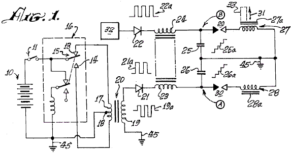
Fig.1 is an explanatory schematic diagram of a capacitor charging and discharging circuit utilised in the present invention.
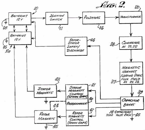
Fig.2 is a block diagram of an exemplary engine system according to the invention.
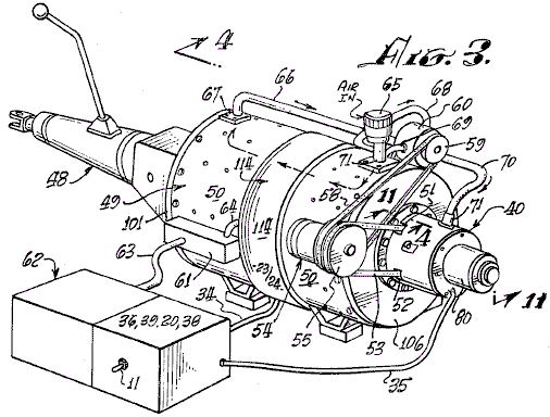
Fig.3 is a perspective view of a typical engine system according to the invention, coupled to an automotive transmission.

Fig.4 is an axial sectional view taken at line 4---4 in Fig.3
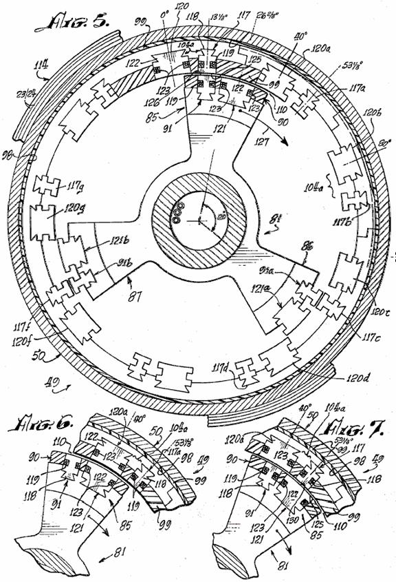
Fig.5 is a sectional view taken at line 5---5 in Fig.4
Fig.6 and Fig.7 are fragmentary sectional views, corresponding to a portion of Fig.5, illustrating successive advanced positions of the engine rotor therein.
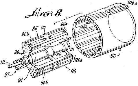
Fig.8 is an exploded perspective view of the rotor and stator of the engine of Fig.3 and Fig.4

Fig.9 is a cross-sectional view taken at line 9---9 of Fig.4
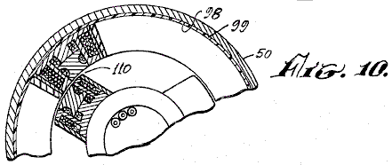
Fig.10 is a partial sectional view, similar to the view of Fig.9, illustrating a different configuration of electromagnets in another engine embodiment of the invention.

Fig.11 is a sectional view taken at line 11---11 in Fig.3, illustrating the control head or novel speed change controlling system of the engine.
Fig.12 is a sectional view, taken at line 12---12 in Fig.11, showing a clutch plate utilised in the speed change control system of Fig.11
Fig.13 is a fragmentary view, taken at line 13---13 in Fig.12
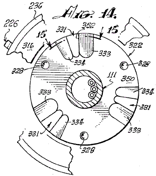
Fig.14 is a sectional view, taken at line 14---14 in Fig.11, showing a clutch plate which co-operates with the clutch plate of Fig.12

Fig.15 is a fragmentary sectional view taken at line 15---15 of Fig.13
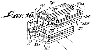
Fig.16 is a perspective view of electromagnets utilised in the present invention.
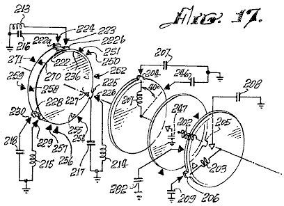
Fig.17 is a schematic diagram showing co-operating mechanical and electrical features of the programmer portion of the invention.
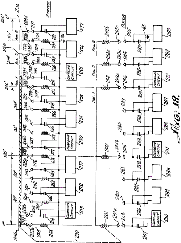
Fig.18 is an electrical schematic diagram of an engine according to the invention, showing the electrical relationships of the electromagnetic components embodying a new principle of the invention, and
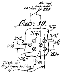
Fig.19 is a developed view, taken at line 19---19 of Fig.11, showing the locations of displaced spark gap elements of the speed changing mechanism of an engine according to the invention.
DESCRIPTION OF THE PREFERRED EMBODIMENT
As mentioned earlier, the basic principle of operation of the engine of the invention, is the discharge of a capacitor across a spark gap and through an inductor. When a pair of inductors is used, and the respective magnetic cores thereof are arranged opposite one another and arranged in opposing magnetic polarity, the discharge through them causes the cores to repel each other with considerable force.
Referring to the electrical schematic diagram of Fig.1, a battery 10 energises a pulse-producing vibrator mechanism 16, which may be of the magnetic type, incorporating an armature 15 moving between contacts 13 and 14, or of the transistor type (not shown) with which a high frequency bipolar pulsed output is produced in primary 17 of transformer 20. The pulse amplitude is stepped up in secondary 19 of transformer 20. Wave form 19a represents the bi-directional or bi-polar pulsed output. A diode rectifier 21 produces a unidirectional pulse train, as indicated at 21a, to charge capacitor 26. Successive unidirectional pulses of wave 21a charge capacitor 26 to high level, as indicated at 26a, until the voltage at point A rises high enough to cause a spark across the spark gap 30. Capacitor 26 discharges via the spark gap, through the electromagnet coil 28. A current pulse is produced which magnetises core 28a. Simultaneously, another substantially identical charging system 32 produces a discharge through inductor 27 across spark gap 29, to magnetise core 27a. Cores 27a and 28a are wound with coils 27 and 28 respectively, so that their magnetic polarities are the same. As the cores 27a and 28a confront one another, they tend to fly apart when the discharge occurs through coils 27 and 28 because of repulsion of identical magnetic poles, as indicated by arrow 31. If core 28a is fixed or stationary, and core 27a is moveable, then core 27a may have tools 33 attached to it to perform work when the capacitor discharges.
Referring to Fig.1 and Fig.2, a d-c electrical source or battery 10, energises pulsators 36 (including at least two vibrators 16 as previously described) when switch 11 between the battery 10 and pulsator 36 is closed, to apply relatively high frequency pulses to the primaries of transformers 20. The secondaries of transformers 20 are step-up windings which apply bipolar pulses, such as pulses 19a (Fig.1) to the diodes in converter 38. The rectified unidirectional pulsating output of each of the diodes in converter 38 is passed through delay coils 23 and 24, thus forming a harness 37, wound about the case of the engine, as herein after described, which is believed to provide a static floating flux field. The outputs from delay lines 37, drive respective capacitors in banks 39, to charge the capacitors therein, to a relatively high charge potential. A programmer and rotor and stator magnet control array 40, 41, 42, is formed by spark gaps positioned, as hereinafter described, so that at predetermined positions of the rotor during rotation of the engine, as hereinafter described, selected capacitors of the capacitor banks 39 will discharge across the spark gaps through the rotor and stator electromagnets 43 and 44. The converters 38, programmer 40, and controls 41 and 42, form a series circuit path across the secondaries of transformers 20 to the ground, or point of reference potential, 45. The capacitor banks 39 are discharged across the spark gaps of programmer 40 (the rotor and stator magnet controls 41 and 42). The discharge occurs through the coils of stator and rotor electromagnets 43 and 44 to ground 45. Stator and rotor electromagnets are similar to those shown at 27, 27a, 28 and 28a in Fig.1.
The discharge through the coils of stator and rotor electromagnets 43 and 44 is accompanied by a discharge overshoot or return pulse, which is applied to a secondary battery 10a to store this excess energy. The overshoot pulse returns to battery 10a because, after discharge, the only path open to it is that to the battery 10a, since the gaps in 40, 41 and 42 have broken down, because the capacitors in banks 39 are discharged and have not yet recovered the high voltage charge from the high frequency pulsers 36 and the converter rectifier units 38.
In the event of a misfire in the programmer control circuits 40, 41 and 42, the capacitors are discharged through a rotor safety discharge circuit 46 and returned to batteries 10-10a, adding to their capacity. The circuit 46 is connected between the capacitor banks 39 and batteries 10, 10a.
Referring to Fig.3, a motor or engine 49 according to the present invention is shown connected with an automotive transmission 48. The transmission 48, represents one of many forms of loads to which the engine may be applied. A motor housing 50, encases the operating mechanism hereinafter described. The programmer 40 is axially mounted at one end of the housing. Through apertures 51 and 52, a belt 53 couples to a pulley 57 (not shown in this view) and to an alternator 54 attached to housing 50. A pulley 55 on the alternator, has two grooves, one for belt 53 to the drive pulley 58 on the shaft (not shown) of the engine 49, and the other for a belt 58 coupled to a pulley 59 on a pump 60 attached to housing 50, A terminal box 61 on the housing, interconnects between the battery assembly 62 and motor 49 via cables 63 and 64.
An intake 65 for air, is coupled to pump 60 via piping 68 and 69 and from pump 60 via tubing or piping 66 and 70 to the interior of housing 50 via coupling flanges 67 and 71. The air flow tends to cool the engine and the air may preferably be maintained at a constant temperature and humidity so that a constant spark gap discharge condition is maintained. A clutch mechanism 80 is provided on programmer 40.
Referring to Fig.4, Fig.5 and Fig.9, rotor 81 has spider assemblies 83 and 84 with three electromagnet coil assembly sets mounted thereon, two of which are shown in Fig.4, on 85, at 85a and 85b and on 86 at 86a and 86b. One of the third electromagnet coil assemblies, designated 87a, is shown in Fig.5, viewed from the shaft end. As more clearly shown in the perspective view of Fig.8, a third spider assembly 88 provides added rigidity and a central support for the rotor mechanism on shaft 81.
The electromagnet sets 85a, 85b, 86a, 86b, 87a and 87b, disposed on rotor 81 and spiders 83, 84 and 88, each comprise pairs of front units 85a, 86a and 87a and pairs of rear units 85b, 86b and 87b. Each pair consists of a major electromagnet and a minor electromagnet, as hereinafter described, which are imbedded in an insulating material 90, which insulates the electromagnet coil assemblies from one another and secures the electromagnets rigidly in place on the spider/rotor cage 81, 83, 84 and 88.
The interior wall 98, of housing 50, is coated with an electrically insulating material 99 in which are imbedded electromagnet coils, as hereinafter described, and the interiors of end plates 100 and 101 of the housing 50. On the insulating surface 98 of housing 50 is mounted a series of stator electromagnet pairs 104a, identical with electromagnet pairs 85a, 86a, 87a, etc. Electromagnet pairs such as 104a or 105a are disposed every 40 degrees about the interior of housing 50 to form a stator which co-operates with the rotor 81-88. An air gap 110 of very close tolerance is defined between the rotor and stator electromagnets and air from pump 65 flows through this gap.
As shown in Fig.8, the electromagnet assemblies, such as 85 through 87, of the rotor and magnet assemblies, such as 104a in the stator, are so embedded in their respective insulating plastic carriers (rotor and stator) that they are smoothly rounded in a concave contour on the rotor to permit smooth and continuous rotation of rotor 81 in stator housing 50. The air gap 110 is uniform at all positions of any rotor element within the stator assembly, as is clearly shown in Fig.16.
The rotor 81 and spiders 83, 84 and 88 are rigidly mounted on shaft 111 journaled in bearing assemblies 112 and 113 which are of conventional type, for easy rotation of the rotor shaft 111 within housing 50.
Around the central outer surface of housing 50, are wound a number of turns of wire 23 and 24 to provide a static flux coil 114 which is a delay line, as previously described. Figs. 5, 6, 7 and 9 are cross-sectional views of the rotor assembly 81-88, arranged to show the positioning and alignment of the rotor and stator electromagnet coil assemblies at successive stages of the rotation of the rotor 81-88 through a portion of a cycle of operation thereof. For example, in Fig.5 the rotor assembly 81-88 is shown so positioned that a minor rotor electromagnet assembly 91 is aligned with a minor stator electromagnet assembly 117.
As shown in further detail in Fig.16, minor electromagnet assembly 117 consists of an iron core 118, grooved so that a coil of wire 119 may be wound around it. Core 118 is the same in stator electromagnet 117 as it is in rotor electromagnet 91.
As a position 13.33 degrees to the right of rotor electromagnet 91, as viewed in Fig.5 and Fig.16, there is a second or major rotor electromagnet 121 which has a winding 123 about its core 122. The electromagnets 91 and 121 are the pair 85a of Fig.4 and Fig.8.
At a position 13.33 degrees to the left of stator electromagnet 117, as viewed in Fig.5, there is a second or major stator electromagnet 120 whose core 122 is of the same configuration as core 122 of rotor electromagnet 121. A winding 123 about core 122 of electromagnet 120 is of the same character as winding 123 on electromagnet 121.
Electromagnet assembly pair 85a on the rotor is identical in configuration to that of the electromagnet stator assembly pair 104a except for the position reversal of the elements 117-120 and 91-121 of the respective pairs.
There are none pairs of electromagnets 120-117 (104a) located at 40 degree intervals about the interior of housing 50. The centreline of core 122 of electromagnet 120 is positioned 13.33 degrees to the left of the centreline of the core 118 of electromagnet 117. Three pairs of electromagnets 85a, 86a and 87a are provided on rotor assembly 81-88 as shown in Fig.5.
Other combinations are possible, but the number of electromagnets in the rotor should always be in integral fraction of the number of electromagnets in the stator. As shown in Fig.8, for the rotor assembly 85a and 85b, there are three of each of the front and back pairs of electromagnetic assemblies. Similarly, as shown in Fig.4 and Fig.8, there are nine front and back pairs of electromagnets in the stator such as 104a and 104b.
In order to best understand the operation of the rotor 81-88 rotating within the stator housing 50 of an engine according to this invention, the positions of rotor electromagnets 91 and stator electromagnets 117 are initially exactly in line at the 13.33 degree peripheral starting position marked on the vertical centreline of Fig.5. The winding direction of the coils of these magnets is such that a d-c current through the coils 119 will produce a particular identical magnet polarity on each of the juxtaposed surfaces 125 of magnet 117 and 126 of magnet 91 (Fig.5). Fig.16 and Fig.6 illustrate the next step in the motion wherein the two major electromagnets, 120 in the stator and 121 in the rotor, are in alignment.
When the d-c discharges from the appropriate capacitors in banks 39 occur simultaneously across spark gaps through the coils 119 of electromagnets 117 and 91, at the instant of their alignment, their cores 118, will repel one another to cause rotor assembly 81-88 to rotate clockwise in the direction indicated by arrow 127. The system does not move in the reverse direction because it has been started in the clockwise direction by the alternator motor 54 shown in Fig.3, or by some other starter means. If started counterclockwise, the motor will continue to rotate counterclockwise.
As noted earlier, the discharge of any capacitor occurs over a very short interval via its associated spark gap and the resulting magnetic repulsion action imparts motion to the rotor. The discharge event occurs when electromagnets 117 and 91 are in alignment. As shown in Fig.5, rotor electromagnet 91a is aligned with stator electromagnet 117c, and rotor electromagnet 91b is aligned with stator electromagnet 117e at the same time that similar electromagnets 117 and 91 are aligned. A discharge occurs through all six of these electromagnets simultaneously (that is, 117, 91, 117c, 91a, 117e and 91b). A capacitor and a spark gap are required for each coil of each electromagnet. Where, as in the assembly shown in Fig.8, front and back pairs are used, both the axial in-line front and back coils are energised simultaneously by the discharge from a single capacitor or from a bank of paralleled capacitors such as 25 and 26 (Fig.1). Although Fig.4 and Fig.8 indicate the use of front and back electromagnets, it should be evident that only a single electromagnet in any stator position and a corresponding single electromagnet in the rotor position, may be utilised to accomplish the repulsion action of the rotor with respect to the stator. As stated, each electromagnet requires a discharge from a single capacitor or capacitor bank across a spark gap for it to be energised, and the magnetic polarity of the juxtaposed magnetic core faces must be the same, in order to effect the repulsive action required to produce the rotary motion.
Referring to Fig.5 and Fig.6, the repulsion action causes the rotor to move 13.33 degrees clockwise, while electromagnets 91, 91a and 91b move away from electromagnets 117, 117c and 117e to bring electromagnets 121, 121a and 121b into respective alignment with electromagnets 120a, 120d and 120f. At this time, a capacitor discharge across a spark-gap into their coils 123 occurs, thus moving the rotor. Another 13.33 degrees ahead, as shown in Fig.7, major electromagnets 121, 121a and 121b come into alignment with minor electromagnets 117a, 117d and 117f, at which time a discharge occurs to repeat the repulsion action, this action continuing as long as d-c power is applied to the system to charge the capacitor banks.
Fig.18 further illustrates the sequencing of the capacitor discharges across appropriate spark gap terminal pairs. Nine single stator coils and three single rotor coils are shown with their respective interconnections with the spark gaps and capacitors with which they are associated for discharge. When the appropriate spark gap terminals are aligned, at the points in the positioning of the rotor assembly for most effective repulsion action of juxtaposed electromagnet cores, the discharge of the appropriate charged capacitors across the associated spark gap occurs through the respective coils. The capacitors are discharged is sets of three, through sets of three coils at each discharge position, as the rotor moves through the rotor positions. In Fig.18, the rotor electromagnets are positioned linearly, rather than on a circular base, to show the electrical action of an electric engine according to the invention. These motor electromagnets 201, 202 and 203 are aligned with stator electromagnets 213, 214 and 215 at 0 degrees, 120 degrees and 240 degrees respectively. The stator electromagnets are correspondingly shown in a linear schematic as if rolled out of the stator assembly and laid side by side. For clarity of description, the capacitors associated with the rotor operation 207, 208, 209 and 246, 247, 248, 249, 282 and 283, are arranged in vertical alignment with the respective positions of the rotor coils 201, 202 and 203 as they move from left to right, this corresponding to clockwise rotation of the rotor. The stator coils 213, 214, 215, 260, 261, 262, 263, 264, 265, 266, etc. and capacitor combinations are arranged side by side, again to facilitate description.
An insulative disc 236 (shown in Fig.17 as a disc but opened out linearly in Fig.18) has mounted thereon, three gap terminal blocks 222, 225 and 228. Each block is rectangularly U-shaped, and each interconnects two terminals with the base of the U. Block 222 has terminals 222a and 222b. Block 225 has terminals 225a and 225b. Block 228 has terminals 228c and 228d. When insulative disc 230 is part of the rotor as indicated by mechanical linkage 290, it can be seen that terminal U 222 creates a pair of gaps with gap terminals 223 and 224 respectively. Thus, when the voltage on capacitor 216 from charging unit 219, is of a value which will arc over the air spaces between 222a and 223, and between 222b and 224, the capacitor 216 will discharge through the coil of electromagnet 213 to ground. Similarly, gap terminal U 225 forms a dual spark gap with gap terminals 226 and 227 to result in arc-over when the voltage on capacitor 217, charged by charging circuit 220, discharges into the coil of electromagnet 214. Also, U-gap terminal 228 with terminals 228c and 228d, creates a spark gap with terminals 229 and 230 to discharge capacitor 218, charged by charging circuit 221, into coil 215. At the same time, rotor coils, 201, 202 and 203 across gaps 201a - 204, 202b - 205 and 203c - 206 each receives a discharge from respective capacitors 207, 208 and 209.
When the electromagnet coils 213, 214 and 215 and 201, 202 and 203 are energised, the repulsion action causes the rotor assembly to move to position 2 where a new simultaneous group of discharges occurs into rotor coils 201, 202 and 203 from capacitors 246, 248 and 282 across gaps 201a - 240, 202b - 242 and 203c - 244. Simultaneously, because gap-U-elements 222, 225 and 228 have also moved to position 2 with the rotor assembly, capacitor 261 is discharged through electromagnet coil 260, capacitor 265 is discharged through electromagnet coil 264, and capacitor 269 is discharged through electromagnet coil 268 in alignment with position 2 of the rotor electromagnet coils, thus to cause the rotor electromagnets to move to position 3 where the discharge pattern is repeated now with capacitors 247, 249 and 283 discharging through the rotor electromagnet coils 201, 202 and 203, and the capacitors 263, 267 and 281 discharging respectively through stator electromagnet coils 262, 266 and 280.
After each discharge, the charging circuits 219 - 221 and 272 - 277 for the stator capacitors, and 210 - 212 and 284 - 289 for the rotor capacitors, are operated continuously from a battery source as described earlier with reference to Fig.1, to constantly recharge the capacitors to which each is connected. Those versed in the art will appreciate that, as each capacitor discharges across an associated spark gap, the resulting drop in potential across the gap renders the gap an open circuit until such time as the capacitor can recharge to the arc-over level for the gap. This recharge occurs before a rotor element arrives at the next position in the rotation.
The mechanical schematic diagram of Fig.17, further clarifies the operation of the spark-gap discharge programming system. A forward disc 236 of an electrically insulative material, has thereon the set of U-shaped gap terminal connectors previously described. These are positioned at 0 degrees, 120 degrees and 240 degrees respectively. In Fig.17, schematic representations of the position of the coil and capacitor arrangements at the start of a cycle are shown to correspond to the above description with reference to Fig.18. Accordingly, the coil and capacitor combinations 213/216, 214/217 and 215/218 are shown connected with their gap terminals, respectively, 223/224, 226/227 and 229/230. On the rotor coil and capacitor connection, three separate discs 291, 292 and 293 are shown, each with a single gap terminal. The discs 291 - 293 are rotated so as to position their respective gap terminals 201a, 201b and 201c, at 120 degree increments, with the 0 degrees position corresponding to the 0 degrees position of U-gap terminal 222 on disc 230.
Representative gap terminals are shown about the peripheries of discs 230, 291 - 293 to indicate clearly how, as the discs turn in unison, the gap alignments correspond so that three rotor coils always line up with three stator coils at 120 degree intervals about the rotary path, producing an alignment every 40 degrees, there being nine stator coils. Thus, there are three simultaneous discharges into stator coils and three into rotor coils at each 40 degree position. Nine positions displaced 40 degrees apart provide a total of 27 discharge points for capacitors into the rotor coils and 27 discharge points for capacitors into the stator coils in one revolution of the rotor.
It will be understood that, as illustrated in Fig.17 and Fig.18, nine individual electromagnet coils are shown in the stator and three in the rotor, in order to show in its simplest form, how the three rotor electromagnets are stepped forward from alignment with three of the stator electromagnets, when the appropriate spark gaps are in alignment, to effect the discharge of capacitors through juxtaposed pairs of rotor/stator electromagnets. The repulsion moves the rotor electromagnet from the stator electromagnet to the next alignment position 40 degrees further on. In the interval, until another rotor electromagnet, 120 degrees removed, is aligned with the stator electromagnet which had just been pulsed, the associated capacitor is recharged. Thus, the rotor moves from one position to the next, with capacitor discharges occurring each 40 degrees of rotation, a total of nine per revolution. It should be obvious that, with other rotor/stator combinations, the number of electromagnet coincidences and spark-gap discharges will vary. For example, with the coil pairs shown in Figs 4 through 8, a total of 27 discharges will occur. Although there are 18 stator electromagnets and 3 rotor electromagnets, the discharge pattern is determined by the specific spark gap arrangement.
The rotor/stator configuration of Fig.5 and Fig.8, involving the major and minor pairs of electromagnets, such as 85a and 104a (the terms “minor” and “major” referring to the difference in size of the elements), include nine pairs of electromagnets in the stator, such as 104a, with three electromagnet pairs of the rotor, such as 85a. Because of the 13.33 degree separation between the major and minor electromagnets in the rotor pair 85a, with the same separation of minor and major electromagnets of the stator pair 104a, the sequence of rotation and discharge described above, with respect to the illustrative example of Fig.5, involves the following:
1. A minor element 117 of stator pair 104a is aligned with the minor element 91 of rotor pair 85a. On the discharge, this moves the rotor ahead 13.33 degrees.
2. the major rotor element 122 of the pair 85a, now is aligned with the major stator element 120b of the next stator electromagnet pair, in the stator array as shown in Fig.6. On the discharge, the rotor moves ahead 13.33 degrees.
3. This brings the minor rotor electromagnet 91 into alignment with the major stator electromagnet 120b of pair 104d, and the major electromagnet 122 (just discharged) of pair 85a into alignment with minor electromagnet 117b of pair 104d, and the rotor spark gap elements into alignment with a different position of gap elements connected with capacitors not discharged in the previous position of the rotor. It should be remembered at this point that it is the positioning of a rotatable spark gap array, similar to that illustrated in Fig.17 and Fig.18, which controls the time of discharge of capacitors connected to these gap terminals. Therefore, any electromagnet can be energised twice, successively, from separate capacitors as the rotor brings appropriate gap terminals into alignment with the coil terminals of a particular electromagnet.
Thus, although major electromagnet 120b of pair 104d has just been energised as described above, it can now be energised again along with minor rotor electromagnet 91 in step 3, because the rotor moved to a new set of terminals of the spark gap arrays connected to capacitors which have not yet been discharged. These capacitors now discharge through rotor electromagnet 91 and stator electromagnet 120b, causing the rotor to move ahead another 13.33 degrees, thus again aligning two minor electromagnets again, these being 117b of stator pair 104d and 91 of rotor pair 85a. The rotor has now moved 40 degrees since step 1 above. The sequence is now repeated indefinitely. It is to be noted that at each 13.33 degree step, the discharges drive the rotor another 13.33 degrees. There are 27 steps per revolution with nine stator coil pairs. The discharge sequence is not uniform, as is shown in Table 1. In the stator, three major electromagnets 120 degrees apart are energised twice in sequence, followed by a hiatus of one step while three minor electromagnets of the stator, 120 degrees apart, are energised during the hiatus. In the rotor the major electromagnets are energised during a hiatus step following two minor electromagnet energisation steps. A total of 27 energisations are this accomplished in the nine pairs of coils of the stator.
In Table 1, the leftmost column shows the location of each rotor arm 85, 86 and 87 at an arbitrarily selected step No. 1 position. For example, in step 1, rotor arm 85 has a minor stator and minor rotor electromagnet in alignment for capacitors to discharge through them simultaneously at the 13.33 degree position.

Similarly, in step 1, rotor arm 86 is at the 133.33 degree position which has two minor electromagnets in alignment, ready for discharge. Simultaneously, rotor arm 87 is at the 253.33 degree position with two minor electromagnets aligned for capacitor discharge. The other steps of the sequence are apparent from Table 1, for each position of the three rotor arms at any step and the juxtapositions of respective stator and rotor electromagnet elements at that position.
In the simplified motor arrangement shown in schematic form in Fig.18, with single electromagnet configuration, the alignment is uniform and the discharge sequences follow sequentially.
As mentioned before, a change in speed is effected by displacing the stator spark gap terminals on the rotor (shown at 236 in Fig.17 and Fig.18) either counterclockwise or clockwise 6.66 degrees so that the discharge position of the stator electromagnets is displaced. Referring to Figs. 11 to 15, the simultaneous discharge of selected capacitors into the displaced electromagnets results in a deceleration if the rotor electromagnet is approaching the stator electromagnet at the time of discharge, or an acceleration if the rotor electromagnet is leaving the stator electromagnet at the time of the discharge pulse. In each event, there is a repulsive reaction between the stator and rotor electromagnets which effects this change in speed.
Referring to Fig.11, clutch mechanism 304 about shaft 111 is operated electromagnetically in conventional manner, to displace the spark-gap mechanism 236 which is operated normally in appropriate matching alignment with the rotor spark-gap discs 291, 292 and 293. Clutch 304 has a fixed drive element 311, containing an electromagnetic drive coil (not shown) and a motor element 310 which, when the electromagnetic drive coil is energised, can be operated by a direct current. The operation of motor element 310, brings into operation, spark gap elements 224r, 223r or 223f, 224f of the system shown in Figs. 4, 5 and 8, as illustrated in Fig.19.
The fixed stator coil spark gap terminal pairs 223, 224 and 266, 267 are arrayed about a cylindrical frame 322 which is fabricated in insulative material. In the illustrative example of Fig.17 and Fig.18, there are nine such spark gap terminal pairs positioned around the periphery of the cylinder frame 324. In the engine of Figs. 4 to 8, a total of 27 such spark gap pairs are involved. In addition, although not shown in the drawing, there are also pairs of terminals, such as 223r or 223f, 224r or 224f and 226r or 226f, 267r or 267f, displaced 6.66 degrees on either side of the pairs 223, 224 or 266, 267 and all other pairs in the spark gap array, the letters “r” and “f” denoting “retard” or “faster”. The latter displaced pairs are used in controlling the speed of the engine rotor. The displaced pairs not shown are involved in the operation of the clutch 304, the speed-changing control element.
Clutch 304 is associated with shaft 111 in that the movable element 310 draws clutch disc element 316 on shaft 111, away from clutch disc element 322 when energised by a voltage of appropriate polarity applied to its motor electromagnet 311. Such clutch drives are well known in the art.
The clutch mechanism 304 of Fig.11 and Fig.19, when not energised, is in the configuration shown in Fig.11. The energised configuration of clutch 304 is not specifically illustrated. Upon energisation, spark-gap element 222 on disc 236 is displaced rightward, as viewed in Fig.11, by broken lines 236X, into alignment with the positions of fixed spark-gap terminals 223f, 224f and 267r, 266r. When the disc is in position 236X, the flattened edge 332 of pin 330 in disc 325 rides on surface 350 of disc 322. Normally, the flattened edges 351 of pins 330 are engaged against the flat edge 352 in recess 331 of disc 322. The displacement of disc 322 on shaft 111 is effected by the action of clutch 304 against spring 314 (Fig.11). An electric switch (not shown) of clutch mechanism 304 energises it from a d-c power source, and has two positions, one for deceleration and one for acceleration. In either position, clutch 304 is engaged to pull clutch disc 322 from clutch disc 325, momentarily. For the decelerate or the accelerate position, the displaced alignment of spark gap elements 222 is with the 224f, 223f and the 224r, 223r spark-gap terminal elements. However, only the 224f, 223f spark-gap elements are switched into operation with appropriate capacitors for the accelerate position, while in the decelerate position, only the 223r and 224r spark-gap elements are switched into the circuit with their associated capacitors.
Of course, when insulative disc 236 is displaced by clutch 304, its gap terminals 222, 225 and 228 (Fig.14 and Fig.18) are all displaced into the alignment position of 236X so as to engage the “r” and “f” lines of fixed spark gap elements. Although the accelerate and decelerate positions of disc 236 are the same, it is the switching into operation of the 223, 224 or 266, 267 exemplary “r” or “f” pairs of terminals which determines whether the rotor will speed up or slow down.
The momentary displacement of clutch disc 322 from clutch disc 325 results in rotation of disc 325 about disc 322 through an angle of 120 degrees. The detent ball and spring mechanism 320, 321 in disc 325, positions itself between one detent dimple 328 and a succeeding one 328 at a position 120 degrees away on disc 325.
As stated, flat 332 of pin 330 rides on surface 350 of disc 322, and pin 330 leaves the pin-holding groove 331/352 along ramp 333 in disc 322 during the momentary lifting of disc 322 by clutch 304. Pin 330 falls back into the next groove 331 at a point 120 degrees further on about disc 322. Pin 330 falls into place in groove 331 on ramp 334. Pins 330 are rotatable in their sockets 353, so that for either clockwise or counterclockwise rotation, the flat 351 will engage the flat 352 by the particular ramp it encounters.
The deceleration or acceleration due to the action of clutch 304 thus occurs within a 120 degree interval of rotation of disc 325. During this interval, disc 322 may only move a fraction of this arc.
There has been described earlier, an electromotive engine system wherein at least one electromagnet is in a fixed position and a second electromagnet of similar configuration is juxtaposed with it in a magnetic polarity relationship such that, when the cores of the electromagnets are energised, the juxtaposed core faces repel each other. One core being fixed, and the second core being free to move, any attachments to the second electromagnet core will move with it. Hence, if a plurality of fixed cores are positioned about a circular confining housing, and, within the housing, cores on a shaft are free to move, the shaft is urged rotationally each time the juxtaposed fixed and rotatable cores are in alignment and energised. Both the fixed and the movable cores are connected to spark gap terminal elements and the associated other terminal elements of the spark gaps are connected to capacitors which are charged to high voltage from pulsed unipolar signal generators. These capacitors are discharged through the electromagnets across the spark gaps. By switching selected groups of capacitors into selected pairs of spark gap elements for discharge through the electromagnets, the rotor of the circular array systems is accelerated and decelerated.
By confining a fixed electromagnet array in a linear configuration, with a linearly movable electromagnet to which a working tool is attached, exciting the juxtaposed pairs of electromagnets by capacitor discharge, results in the generation of linear force for such tools as punch presses, or for discharging projectiles with considerable energy.
EDWIN GRAY: POWER SUPPLY
US Patent 4,595,975 June 17, 1986 Inventor: Edwin V. Gray snr.
EFFICIENT POWER SUPPLY SUITABLE FOR INDUCTIVE LOADS

Please note
that this is a re-worded excerpt from this patent. It describes the circuitry used with Edwin
Gray’s power tube. Please be aware
Edwin wanted at all costs, to conceal any useful technology while getting
patents to encourage investors, so please understand that this patent is not
intended to tell you how to make a working system of this type.
Fig.1 is a schematic circuit diagram of the electrical driving system.
Fig.2 is an elevational sectional view of the electrical conversion element.
Fig.3 is a plan sectional view taken along line 3--3 of Fig.2.
Fig.4 is a plan sectional view taken along line 4--4 of Fig.2.
Fig.5 is a schematic circuit diagram of the alternating-current input circuit.
SUMMARY OF THE INVENTION
The present invention provides a more efficient driving system comprising a source of electrical voltage; a vibrator connected to the low-voltage source for forming a pulsating signal; a transformer connected to the vibrator for receiving the pulsating signal; a high-voltage source, where available, connected to a bridge-type rectifier; or the bridge-type rectifier connected to the high voltage pulse output of the transformer; a capacitor for receiving the voltage pulse output; a conversion element having first and second anodes, electrically conductive means for receiving a charge positioned about the second anode and an output terminal connected to the charge receiving means, the second anode being connected to the capacitor; a commutator connected to the source of electrical voltage and to the first anode; and an inductive load connected to the output terminal whereby a high energy discharge between the first and second anodes is transferred to the charge receiving means and then to the inductive load.
As a sub-combination, the present invention also includes a conversion element
comprising a housing; a first low voltage anode mounted to the housing, the
first anode adapted to be connected to a voltage source; a second high voltage
anode mounted to the housing, the second anode adapted to be connected to a
voltage source; electrically conductive means positioned about the second anode
and spaced therefrom for receiving a charge, the charge receiving means being
mounted to the housing; and an output terminal communicating with the charge
receiving means, said terminal adapted to be connected to an inductive load.
The invention also includes a method for providing power to an inductive load
comprising the steps of providing a voltage source, pulsating a signal from
said source; increasing the voltage of said signal; rectifying said signal;
storing and increasing the signal; conducting said signal to a high voltage
anode; providing a low voltage to a second anode to form a high energy
discharge; electrostatically coupling the discharge to a charge receiving
element; conducting the discharge to an inductive load; coupling a second
capacitor to the load; and coupling the second capacitor to the source.
It is an aim of the present invention to provide a system for driving an
inductive load which system is substantially more efficient than any now
existing. Another object of the present
invention is to provide a system for driving an inductive load which is reliable,
is inexpensive and simply constructed.
The foregoing objects of the present invention together with various other
objects, advantages, features and results thereof which will be evident to
those skilled in the art in light of this disclosure may be achieved with the
exemplary embodiment of the invention described in detail hereinafter and
illustrated in the accompanying drawings.
DESCRIPTION
OF THE PREFERRED EMBODIMENT
While the present invention is susceptible of various modifications and alternative constructions, an embodiment is shown in the drawings and will herein be described in detail. It should be understood however that it is not the intention to limit the invention to the particular form disclosed; but on the contrary, the invention is to cover all modifications, equivalents and alternative constructions falling within the spirit and scope of the invention as expressed in the appended claims.
There is disclosed herein an electrical driving system which, on theory, will
convert low voltage electric energy from a source such as an electric storage
battery to a high potential, high current energy pulse that is capable of
developing a working force at the inductive output of the device that is more
efficient than that which is capable of being developed directly from the
energy source. The improvement in efficiency is further enhanced by the
capability of the device to return that portion of the initial energy
developed, and not used by the inductive load in the production of mechanical
energy, to the same or second energy reservoir or source for use elsewhere, or
for storage.
This system accomplishes the results stated above by harnessing the
“electrostatic” or “impulse” energy created by a high-intensity spark generated
within a specially constructed electrical conversion switching element tube.
This element utilises a low-voltage anode, a high-voltage anode, and one or
more “electrostatic” or charge receiving grids. These grids are of a physical
size, and appropriately positioned, as to be compatible with the size of the
tube, and therefore, directly related to the amount of energy to be anticipated
when the device is operating.
The low-voltage anode may incorporate a resistive device to aid in controlling
the amount of current drawn from the energy source. This low-voltage anode is
connected to the energy source through a mechanical commutator or a solid-state
pulser that controls the timing and duration of the energy spark within the
element. The high-voltage anode is connected to a high- voltage potential
developed by the associated circuits. An energy discharge occurs within the
element when the external control circuits permit. This short duration,
high-voltage, high-current energy pulse is captured by the “electrostatic”
grids within the tube, stored momentarily, then transferred to the inductive
output load.
The increase in efficiency anticipated in converting the electrical energy to
mechanical energy within the inductive load is attributed to the utilisation of
the most optimum timing in introducing the electrical energy to the load
device, for the optimum period of time.
Further enhancement of energy conservation is accomplished by capturing a
significant portion of the energy generated by the inductive load when the
useful energy field is collapsing. This energy is normally dissipated in load
losses that are contrary to the desired energy utilisation, and have heretofore
been accepted because no suitable means had been developed to harness this
energy and restore it to a suitable energy storage device.
The present invention is concerned with two concepts or characteristics. The
first of these characteristics is observed with the introduction of an
energising cur- rent through the inductor. The inductor creates a contrary
force (counter-electromotive force or CEMP) that opposes the energy introduced
into the inductor. This CEMF increases throughout the time the introduced
energy is increasing.
In normal applications of an alternating-current to an inductive load for
mechanical applications, the useful work of the inductor is accomplished prior
to terminating the application of energy. The excess energy applied is thereby
wasted.
Previous attempts to provide energy inputs to an inductor of time durations
limited to that period when the optimum transfer of inductive energy to mechanical
energy is occurring, have been limited by the ability of any such device to
handle the high current required to optimise the energy transfer.
The second characteristic is observed when the energising current is removed
from the inductor, As the current is decreased, the inductor generates an EMF
that opposes the removal of current or, in other words, produces an energy
source at the output of the inductor that simulates the original energy source,
reduced by the actual energy removed from the circuit by the mechanical load.
This “regenerated”, or excess, energy has previously been lost due to a failure
to provide a storage capability for this energy.
In this invention, a high-voltage, high-current, short duration energy pulse is
applied to the inductive load by the conversion element. This element makes
possible the use of certain of that energy impressed within an arc across a
spark-gap, without the resultant deterioration of circuit elements normally
associated with high energy electrical arcs.
This invention also provides for capture of a certain portion of the energy
induced by the high inductive kick produced by the abrupt withdrawal of the
introduced current. This abrupt withdrawal of current is attendant upon the
termination of the stimulating arc. The voltage spike so created is imposed
upon a capacitor that couples the attendant current to a secondary energy
storage device.
A novel, but not essential, circuit arrangement provides for switching the
energy source and the energy storage device. This switching may be so arranged
as to actuate automatically at predetermined times. The switching may be at
specified periods determined by experimentation with a particular device, or
may be actuated by some control device that measures the relative energy
content of the two energy reservoirs.
Referring now to Fig.1, the system 10 will be described in additional
detail. The potential for the high- voltage anode, 12 of the conversion element 14
is developed across the capacitor 16.
This voltage is produced by drawing a low current from a battery source 18 through the vibrator 20. The effect of the vibrator is to
create a pulsating input to the transformer 22. The turns ratio of the transformer is chosen to optimise the
volt- age applied to a bridge-type rectifier 24. The output of the rectifier is then a series of high-voltage
pulses of modest current. When the available source is already of the high
voltage, AC type, it may be coupled directly to the bridge-type rectifier.
By repetitious application of these output pulses from the bridge-type
rectifier to the capacitor 16, a
high-voltage, high-level charge is built up on the capacitor.
Control of the conversion switching element tube is maintained by a commutator 26. A series of contacts mounted radially
about a shafts or a solid-state switching device sensitive to time or other
variable may be used for this control element. A switching element tube type
one-way energy path 28 is introduced
between the commutator device and the conversion switching element tube to
prevent high energy arcing at the commutator current path. When the switching
element tube is closed, current from the voltage source 18 is routed through a resistive element 30 and a low voltage anode 32.
This causes a high energy discharge between the anodes within the conversion
switching element tube 14.
The energy content of the high energy pulse is electrostatically coupled to the
conversion grids 34 of the
conversion element. This electrostatic charge is applied through an output
terminal 60 (Fig.2) across the load inductance 36, inducing a strong electromagnetic field about the inductive
load. The intensity of this electromagnetic field is determined by the high
electromotive potential developed upon the electrostatic grids and the very
short time duration required to develop the energy pulse.
If the inductive load is coupled magnetically to a mechanical load, a strong
initial torque is developed that may be efficiently utilised to produce
physical work
Upon cessation of the energy pulse (arc) within the conversion switching
element tube the inductive load is decoupled, allowing the electromagnetic
field about the inductive load to collapse. The collapse of this energy field
induces within the inductive load a counter EMF. This counter EMF creates a high positive
potential across a second capacitor which, in turn, is induced into the second
energy storage device or battery 40
as a charging current. The amount of charging current available to the battery
40 is dependent upon the initial conditions within the circuit at the time of
discharge within the conversion switching element tube and the amount of
mechanical energy consumed by the workload.
A spark-gap protection device 42 is
included in the circuit to protect the inductive load and the rectifier
elements from unduly large discharge currents. Should the potentials within the
circuit exceed predetermined values, fixed by the mechanical size and spacing
of the elements within the protective device, the excess energy is dissipated
(bypassed) by the protective device to the circuit common (electrical ground).
Diodes 44 and 46 bypass the excess overshoot generated when the “Energy
Conversion Switching Element Tube” is triggered. A switching element U allows
either energy storage source to be used as the primary energy source, while the
other battery is used as the energy retrieval unit. The switch facilitates
interchanging the source and the retrieval unit at optimum intervals to be
determined by the utilisation of the conversion switching element tube. This
switching may be accomplished manually or automatically, as determined by the
choice of switching element from among a large variety readily available for
the purpose.
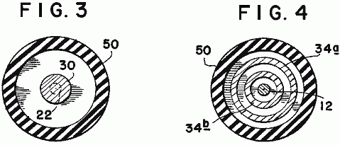
Fig.2, Fig.3, and Fig.4 show the mechanical structure of the conversion switching element tube 14. An outer housing 50 may be of any insulative material such as glass. The anodes 12 and 22 and grids 34a and 34b are firmly secured by nonconductive spacer material 54, and 56. The resistive element 30 may be introduced into the low-voltage anode path to control the peak currents through the conversion switching element tube. The resistive element may be of a piece, or it may be built of one or more resistive elements to achieve the desired result.
The anode material may be identical for each anode, or may be of differing
materials for each anode, as dictated by the most efficient utilisation of the
device, as determined by appropriate research at the time of production for the
intended use. The shape and spacing of
the electrostatic grids is also susceptible to variation with application
(voltage, current, and energy requirements).
It is the contention of the inventor that by judicious mating of the elements
of the conversion switching element tube, and the proper selection of the
components of the circuit elements of the system, the desired theoretical
results may be achieved. It is the inventor’s contention that this mating and
selection process is well within the capabilities of intensive research and
development technique.
Let it be stated here that substituting a source of electric
alternating-current subject to the required cur- rent and/or voltage shaping
and/or timing, either prior to being considered a primary energy source, or
there- after, should not be construed to change the described utilisation or
application of primary energy in any way. Such energy conversion is readily
achieved by any of a multitude of well established principles. The preferred
embodiment of this invention merely assumes optimum utilisation and optimum
benefit from this invention when used with portable energy devices similar in
principle to the wet-cell or dry-cell battery.
This invention proposes to utilise the energy contained in an internally
generated high-voltage electric spike (energy pulse) to electrically energise
an inductive load.: this inductive load being then capable of converting the
energy so supplied into a useful electrical or mechanical output.
In operation the high-voltage, short-duration electric spike is generated by
discharging the capacitor 16 across
the spark-gap in the conversion switching element tube. The necessary
high-voltage potential is stored on the capacitor in incremental, additive
steps from the bridge-type rectifier 24. When the energy source is a direct-current
electric energy storage device, such as the battery 12, the input to the bridge rectifier is provided by the voltage
step-up transformer 22, that is in
turn energised from the vibrator 20,
or solid-state chopper, or similar device to properly drive the transformer and
rectifier circuits.
When the energy source is an alternating-current, switches 64 disconnect transformer 22
and the input to the bridge-type rectifier 24
is provided by the voltage step-up transformer 66, that is in turn energised from the vibrator 20, or solid-state chopper, or similar
device to properly drive the transformer and rectifier circuits.
The repetitions output of the bridge rectifier incrementally increases the
capacitor charge toward its maximum. This charge is electrically connected
directly to the high-voltage anode 12
of the conversion switching element tube.
When the low-voltage anode 32
is connected to a source of current, an arc is created in the spark-gap
designated 62 of the conversion
switching element tube equivalent to the potential stored on the high-voltage
anode, and the current available from the low-voltage anode.
Because the duration of the arc is very short, the instantaneous voltage, and
instantaneous current may both be very high. The instantaneous peak apparent
power is therefore, also very high. Within the conversion switching element
tube, this energy is absorbed by the grids 34a
and 34b mounted circumferentially
about the interior of the tube.
Control of the energy spike within the conversion switching element tube is
accomplished by a mechanical, or solid-state commutator, that closes the
circuit path from the low-voltage anode to the current source at that moment
when the delivery of energy to the output load is most auspicious. Any number of
standard high-accuracy, variable setting devices are available for this
purpose. When control of the repetitive rate of the system’s output is
required, it is accomplished by controlling the time of connection at the
low-voltage anode.
Thus there can be provided an electrical driving system having a low-voltage
source coupled to a vibrator, a transformer and a bridge-type rectifier to
provide a high voltage pulsating signal to a first capacitor. Where a
high-voltage source is otherwise available, it may be coupled direct to a
bridge-type rectifier, causing a pulsating signal to a first capacitor. The
capacitor in turn is coupled to a high-voltage anode of an electrical
conversion switching element tube. The element also includes a low-voltage
anode which in turn is connected to a voltage source by a commutator, a
switching element tube, and a variable resistor. Mounted around the
high-voltage anode is a charge receiving plate which in turn is coupled to an
inductive load to transmit a high-voltage discharge from the element to the
load. Also coupled to the load is a second capacitor for storing the back EMF
created by the collapsing electrical field of the load when the current to the
load is blocked. The second capacitor in turn is coupled to the voltage source.
ASPDEN & ADAMS: MOTOR / GENERATOR
Patent GB 2,282,708 12th
April 1995 Inventors: Harold
Aspden and Robert Adams
ELECTRICAL MOTOR / GENERATOR
This version of the patent has been re-worded in an attempt to make it easier to read and understand. It describes the design of a pulsed electromagnet / permanent magnet motor which is capable of a higher power output than it’s own power input.
ABSTRACT
An electrodynamic motor-generator has a salient pole permanent magnet rotor interacting with salient stator poles to form a machine operating on the magnetic reluctance principle. The intrinsic ferromagnetic power of the magnets provides the drive torque by bringing the poles into register whilst current pulses demagnetise the stator poles as the poles separate. In as much as less power is needed for stator demagnetisation than is fed into the reluctance drive by the thermodynamic system powering the ferromagnetic state, the machine operates regeneratively by virtue of stator winding interconnection with unequal number of rotor and stator poles. A rotor construction is disclosed (Fig.6 and Fig.7). The current pulse may be such as to cause repulsion of the rotor poles.
FIELD OF THE INVENTION
This invention relates to a form of electric motor which serves a generating function in that the machine can act regeneratively to develop output electrical power or can generate mechanical drive torque with unusually high efficiency in relation to electrical power input.
The field of invention is that of switched reluctance motors, meaning machines which have salient poles and operate by virtue of the mutual magnetic attraction and/or repulsion as between magnetised poles.
The invention particularly concerns a form of reluctance motor which incorporates permanent magnets to establish magnetic polarisation.
BACKGROUND OF THE INVENTION
There have been proposals in the past for machines in which the relative motion of magnets can in some way develop unusually strong force actions which are said to result in more power output than is supplied as electrical input.
By orthodox electrical engineering principles such suggestions have seemed to contradict accepted principles of physics, but it is becoming increasingly evident that conformity with the first law of thermodynamics allows a gain in the electromechanical power balance provided it is matched by a thermal cooling.
In this sense, one needs to extend the physical background of the cooling medium to include, not just the machine structure and the immediate ambient environment, but also the sub-quantum level of what is termed, in modern physics, the zero-point field. This is the field activity of the vacuum medium which exists in the space between atomic nuclei and atomic electrons and is the seat of the action which is that associated with the Planck constant. Energy is constantly being exchanged as between that activity and coextensive matter forms but normally these energy fluctuations preserve, on balance, an equilibrium condition so that this action passes unnoticed at the technology level.
Physicists are becoming more and more aware of the fact that, as with gravitation, so magnetism is a route by which we can gain access to the sea of energy that pervades the vacuum. Historically, the energy balance has been written in mathematical terms by assigning 'negative' potential to gravitation or magnetism. However, this is only a disguised way of saying that the vacuum field, suitably influenced by the gravitating mass of a body in the locality or by magnetism in a ferromagnet has both the capacity and an urge to shed energy.
Now, however, there is growing awareness of the technological energy generating potential of this field background and interest is developing in techniques for 'pumping' the coupling between matter and vacuum field to derive power from that hidden energy source. Such research may establish that this action will draw on the 2.7K cosmic background temperature of the space medium through which the Earth travels at some 400 km/s. The effect contemplated could well leave a cool 'vapour trail' in space as a machine delivering heat, or delivering a more useful electrical form of energy that will revert to heat, travels with body Earth through that space.
In pure physics terms, relevant background is of recent record in the August 1993 issue of Physical Review E, vol. 48, pp. 1562-1565 under the title: 'Extracting energy and heat from the vacuum', authored by D. C. Cole and H. E. Puthoff. Though the connection is not referenced in that paper, one of its author's presented experimental evidence on that theme at an April 1993 conference held in Denver USA. The plasma power generating device discussed at that conference was the subject of U. S. Patent No. 5,018,180, the inventor of record being K. R. Shoulders.
The invention, to be described below, operates by extracting energy from a magnetic system in a motor and the relevant scientific background to this technology can be appreciated from the teachings of E. B. Moullin, a Cambridge Professor of Electrical Engineering who was a President of the Institution of Electrical Engineers in U. K. That prior art will be described below as part of the explanation of the operation of the invention.
The invention
presented here concerns specific structural design features of a machine
adapted for robust operation, but these also have novelty and special merit in
a functional operation. What is described is quite distinct from prior art
proposals, one being a novel kind of motor proposed by Gareth Jones at a 1988
symposium held in
However, the Jones machine is not one exploiting the advantages of the invention to be described, because it is not strictly a reluctance motor having salient poles on both stator and rotor. The stator poles in the
Jones machine are formed by the winding configuration in a slotted stator form, the many slots being uniformly distributed around the inner circumference of the stator and not constituting a pole system which lends itself to the magnetic flux actions to be described by reference to the E. B. Moullin experiment.
The Jones machine operates by generating a rotating stator field which, in a sense, pushes the rotor poles forward rather than pulling them in the manner seen in the normal synchronous motor. Accordingly, the Jones machine relies on the electric current excitation of the motor producing a field system which rotates smoothly but has a polarity pattern which is forced by the commutation control to keep behind the rotor poles in asserting a continuous repulsive drive.
Another prior art proposal which is distinguished from this invention is that of one of the applicants, H. Aspden, namely the subject of U.K. Patent No. 2,234,863 (counterpart U.S. Patent Serial No.4,975,608). Although this latter invention is concerned with extracting energy from the field by the same physical process as the subject invention, the technique for accessing that energy is not optimum in respect of the structure or method used. Whereas in this earlier disclosure, the switching of the reluctance drive excited the poles in their approach phase, the subject invention, in one of its aspects, offers distinct advantages by demagnetisation or reversal of magnetisation in the pole separation phase of operation.
There are unexpected advantages in the implementation proposed by the subject invention, inasmuch as recent research has confirmed that it requires less input power to switch off the mutual attraction across an air gap between a magnet and an electromagnet than it does to switch it on. Usually, in electromagnetism, a reversal symmetry is expected, arising from conventional teaching of the way forward and back magnetomotive forces govern the resulting flux in a magnetic circuit.
This will be further explained after describing the scope of the invention.
BRIEF
DESCRIPTION OF THE INVENTION
According to one aspect of the invention, an electrodynamic motor/generator machine comprises a stator configured to provide a set of stator poles, a corresponding set of magnetising windings mounted on the stator pole set, a rotor having two sections each of which has a set of salient pole pieces, the rotor sections being axially spaced along the axis of rotation of the rotor, rotor magnetisation means disposed between the two rotor sections arranged to produce a unidirectional magnetic field which magnetically polarises the rotor poles, whereby the pole faces of one rotor section all have a north polarity and the pole faces of the other rotor section all have a south polarity and electric circuit connections between an electric current source and the stator magnetising windings arranged to regulate the operation of the machine by admitting current pulses for a duration determined according to the angular position of the rotor, which pulses have a direction tending to oppose the polarisation induced in the stator by the rotor polarisation as stator and rotor poles separate from an in-register position, whereby the action of the rotor magnetisation means provides a reluctance motor drive force to bring stator and rotor poles into register and the action of the stator magnetisation windings opposes the counterpart reluctance braking effect as the poles separate.
According to a feature of the invention, the circuit connecting the electric current source and the stator magnetising windings is designed to deliver current pulses which are of sufficient strength and duration to provide demagnetisation of the stator poles as the stator and rotor poles separate from an in-register position.
In this regard it is noted that in order to suppress the reluctance drive torque or brake torque, depending upon whether poles are converging or separating, a certain amount of electrical power must be fed to the magnetising windings on the stator. In a sense these windings are really 'demagnetising windings' because the polarity of the circuit connections admit the pulse current in the demagnetising direction.
However, it is more usual to refer to windings on magnetic cores as 'magnetising windings' even though they can function as primary windings or secondary windings, the former serving the magnetisation function with input power and the latter serving a demagnetising function with return of power.
According to another feature of the invention, the circuit connecting the electric current source and the stator magnetising windings is designed to deliver current pulses which are of sufficient strength and duration to provide a reversal of magnetic flux direction in the stator poles as the stator and rotor poles separate from an in-register position, whereby to draw on power supplied from the electric current source to provide additional forward drive torque.
According to a further feature of the invention, the electric current source connected to a stator magnetising winding of a first stator pole comprises, at least partially, the electrical pulses induced in the stator magnetising winding of a different second stator pole, the stator pole set configuration in relation to the rotor pole set configuration being such that the first stator pole is coming into register with a rotor pole as the second stator pole separates from its in-register position with a rotor pole.
This means that the magnetising windings of two stator poles are connected so that both serve a 'demagnetising' function, one in resisting the magnetic action of the mutual attraction in pulling poles into register, an action which develops a current pulse output and one in absorbing this current pulse, again by resisting the magnetic inter-pole action to demagnetise the stator pole as its associated rotor pole separates.
In order to facilitate the function governed by this circuit connection between stator magnetising windings, a phase difference is needed and this is introduced by designing the machine to have a different number of poles in a set of stator poles from the number of rotor poles in each rotor section. Together with the dual rotor section feature, this has the additional merit of assuring a smoother torque action and reducing magnetic flux fluctuations and leakage effects which contribute substantially to machine efficiency.
Thus, according to another feature of the invention, the stator configuration provides pole pieces which are common to both rotor sections in the sense that when stator and rotor poles are in-register the stator pole pieces constitute bridging members for magnetic flux closure in a magnetic circuit including that of the rotor magnetisation means disposed between the two rotor sections.
Preferably, the number of poles in a set of stator poles and the number of rotor poles in each section do not share a common integer factor, the number of rotor poles in one rotor section is the same as that in the other rotor section and the number of poles in a stator set and the number of poles in a rotor section differs by one, with the pole faces being of sufficient angular width to assure that the magnetic flux produced by the rotor magnetisation means can find a circular magnetic flux closure route through the bridging path of a stator pole and through corresponding rotor poles for any angular position of the rotor.
It is also preferable from a design viewpoint for the stator pole faces of this invention to have an angular width that is no greater than half the angular width of a rotor pole and for the rotor sections to comprise circular steel laminations in which the rotor poles are formed as large teeth at the perimeter with the rotor magnetisation means comprising a magnetic core structure the end faces of which abut two assemblies of such laminations forming the two rotor sections.
According to a further feature of the invention, the rotor magnetisation means comprises at least one permanent magnet located with its polarisation axis parallel with the rotor axis. The motor-generator may include an apertured metal disc that is of a non-magnetisable substance mounted on a rotor shaft and positioned intermediate the two rotor sections, each aperture providing location for a permanent magnet, whereby the centrifugal forces acting on the permanent magnet as the rotor rotates are absorbed by the stresses set up in the disc. Also, the rotor may be mounted on a shaft that is of a non-magnetisable substance, whereby to minimise magnetic leakage from the rotor magnetising means through that shaft.
According to another aspect of the invention, an electrodynamic motor-generator machine comprises a stator configured to provide a set of stator poles, a corresponding set of magnetising windings mounted on the stator pole set, a rotor having two sections each of which has a set of salient pole pieces, the rotor sections being axially spaced along the axis of rotation of the rotor, rotor magnetisation means incorporated in the rotor structure and arranged to polarise the rotor poles, whereby the pole faces of one rotor section all have a north polarity and the pole faces of the other rotor section all have a south polarity and electric circuit connections between an electric current source and the stator magnetising windings arranged to regulate the operation of the machine by admitting current pulses for a duration determined according to the angular position of the rotor, which pulses have a direction tending to oppose the polarisation induced in the stator by the rotor polarisation as stator and rotor poles separate from an in-register position, whereby the action of the rotor magnetisation means provides a reluctance motor drive force to bring stator and rotor poles into register and the action of the stator magnetisation windings opposes the counterpart reluctance braking effect as the poles separate.
According to a feature of this latter aspect of the invention, the electric current source connected to a stator magnetising winding of a first stator pole comprises, at least partially, the electrical pulses induced in the stator magnetising winding of a different second stator pole, the stator pole set configuration in relation to the rotor pole set configuration being such that the first stator pole is coming into register with a rotor pole as the second stator pole separates from its in-register position with a rotor pole.
BRIEF DESCRIPTION OF THE DRAWINGS
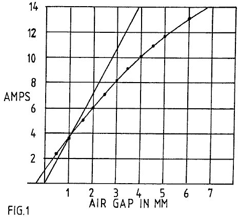
Fig.1 presents magnetic core test data showing how the volt-amp reactance power required to set up a constant magnetic flux action in an air gap, as assured by constant AC voltage excitation of a magnetising winding, falls short of the associated power of the potential implicit in the force action across that air gap.
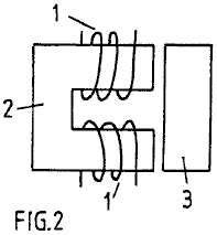
Fig.2 depicts the test structure to which Fig. 1 data applies.
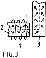
Fig.3 depicts the magnetisation action at work in causing magnetic flux to traverse an air-gap and turn a corner in a circuit through a magnetic core.
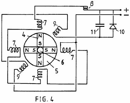
Fig.4 shows the configuration of a test device used to prove the operating principles of the invention described.

Fig.5 in its several illustrations depicts the progressive rotor pole to stator pole relationship as a rotor turns through a range of angular positions in a preferred embodiment of a machine according to the invention.

Fig.6 shows the form of a disc member which provides location for four permanent magnets in the machine described.
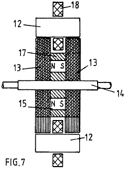
Fig.7 shows a cross-section of the magnetic circuit structure of a machine embodying the invention.
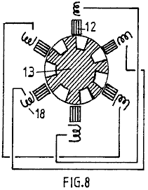
Fig.8 shows a six stator pole configuration with a seven pole rotor and depicts a schematic series connected linking of the magnetising windings of diametrically opposite stator poles.
DETAILED
DESCRIPTION OF THE INVENTION
The fact that
one can extract energy from the source which powers the intrinsic ferromagnetic
state is not explicitly evident from existing textbooks, but it is implicit
and, indeed, does become explicit once pointed out, in one textbook authored by
E. B. Moullin. His book 'The Principles
of Electromagnetism' published by Clarendon Press,
The data show that, even though the level of magnetic polarisation is well below the saturation value, being confined to a range that is regarded as the linear permeability range in transformer design, there is a clear drop-off of current, and so the volt-amp reactive power input needed, as current increases, compared with that predicted by the mechanical potential built up in the air gaps. Unless leakage flux is excessive, here was clear evidence of anomalous energy activity.
Moullin discusses the leakage flux inferred by this experiment but points out that there is considerable mystery in why the effect of a small gap, which should certainly not result in much flux leakage in the gap region, nevertheless has an enormous effect in causing what has to be substantial leakage in the light of the energy discrepancy. Moullin did not contemplate that energy had been fed in from the zero-point field system and so he left the issue with the statement that it was virtually impossible to predict leakage flux by calculation.
He was, of course, aware of magnetic domain structure and his argument was that the leakage flux problem was connected with what he termed a 'yawing' action of the flux as it passes around the magnetic circuit. Normally, provided the level of polarisation is below the knee of the B-H curve, which occurs at about 70% of saturation in iron cores of general crystal composition, it requires very little magnetising field to change the magnetic flux density. This is assuming that every effort is made to avoid air gaps. The action involves domain wall movements so that the magnetic states of adjacent domains switch to different crystal axes of easy magnetisation and this involves very little energy change.
However, if there is an air gap ahead in the flux circuit and the magnetising winding is not sitting on that air gap, the iron core itself has to be the seat of a progressive field source linking the winding and the gap. It can only serve in that sense by virtue of the lines of flux in the domains being forced to rotate somewhat from the preferred easy axes of magnetisation, with the help of the boundary surfaces around the whole core. This action means that, forcibly, and consequential upon the existence of the air gap, the flux must be carried through the core by that 'yawing' action. It means that substantial energy is needed to force the establishment of those fields within the iron core. More important, however, from the point of view of this invention, it means that the intrinsic magnetic polarisation effects in adjacent magnetic domains in the iron cease to be mutually parallel or orthogonal so as to stay directed along axes of easy magnetisation. Then, in effect, the magnetising action is not just that of the magnetising winding wrapped around the core but becomes also that of adjacent ferromagnetic polarisation as the latter act in concert as vacuum-energy powered solenoids and are deflected into one another to develop the additional forward magnetomotive forces.
The consequences of this are that the intrinsic ferromagnetic power source with its thermodynamic ordering action contributes to doing work in building up forces across the air gap. The task, in technological terms, is then to harness that energy as the gap is closed, as by poles coming together in a reluctance motor, and avoid returning that energy as the poles separate, this being possible if the controlling source of primary magnetisation is well removed from the pole gap and the demagnetisation occurs when the poles are at the closest position.
This energy situation is evident in the Moullin data, because the constant AC voltage implies a constant flux amplitude across the air gap if there is no flux leakage in the gap region. A constant flux amplitude implies a constant force between the poles and so the gap width in relation to this force is a measure of the mechanical energy potential of the air gap. The reactive volt-amp power assessment over the quarter-cycle period representing the polarisation demand can then be compared with the mechanical energy so made available. As already stated, this is how Moullin deduced the theoretical current curve. In fact, as his data show, he needed less current than the mechanical energy suggested and so he had in his experiment evidence of the vacuum energy source that passed unnoticed and is only now revealing itself in machines that can serve our energy needs.
In the research leading to this patent application the Moullin experiment has been repeated to verify a condition where a single magnetising winding serves three air gaps. The Moullin test configuration is shown in Fig.2, but in repeating the experiment in the research leading to this invention, a search coil was mounted on the bridging member and this was used to compare the ratio of the voltage applied to the magnetising winding and that induced in the search coil.
The same fall-off feature in current demand was observed, and there was clear evidence of substantial excess energy in the air gap. This was in addition to the inductive energy that necessarily had to be locked into the magnetic core to sustain the 'yawing' action of the magnetic flux already mentioned.
It is therefore emphasised that, in priming the flux 'yawing' action, energy is stored inductively in the magnetic core, even though this has been deemed to be the energy of flux leakage outside the core. The air gap energy is also induction energy. Both energies are returned to the source winding when the system is demagnetised, given a fixed air gap.
If, however, the air gap closes after or during magnetisation, much of that inductive energy goes into the mechanical work output. Note then that the energy released as mechanical work is not just that stored in the air gap but is that stored in sustaining the 'yaw'. Here, then is reason to expect an even stronger contribution to the dynamic machine performance, one that was not embraced by the calculation of the steady-state situation.
Given the above explanation of the energy source, the structural features which are the subject of this invention will now be described.
The 'yawing' action is depicted in Fig.3, which depicts how magnetic flux navigates a right-angled bend in a magnetic core upon passage through an air gap. By over-simplification it is assumed that the core has a crystal structure that has a preferred axis of magnetisation along the broken line path. With no air gap, the current needed by a magnetising winding has only to provide enough magnetomotive force to overcome the effects of non-magnetic inclusions and impurities in the core substance and very high magnetic permeabilities can apply. However, as soon as the air gap develops, this core substance has to find a way of setting up magnetomotive force in regions extending away from the locality of the magnetising winding. It cannot do this unless its effect is so powerful that the magnetic flux throughout the magnetic circuit through the core substance is everywhere deflected from alignment with a preferred easy axis of magnetisation. Hence the flux vectors depicted by the arrows move out of alignment with the broken line shown.
There is a 'knock-on' effect progressing all the way around the core from the seat of the magnetising winding and, as already stated, this harnesses the intrinsic ferromagnetic power that, in a system with no air gap, could only be affected by magnetisation above the knee of the B-H curve. Magnetic flux rotation occurs above that knee, whereas in an ideal core the magnetism develops with very high permeability over a range up to that knee, because it needs very little power to displace a magnetic domain wall sideways and promote a 900 or a1800 flux reversal. Indeed, one can have a magnetic permeability of 10,000 below the knee and 100 above the knee, the latter reducing progressively until the substance saturates magnetically.
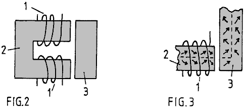
In the situation depicted in Fig.2 and Fig.3 the field strength developed by the magnetising windings 1 on magnetic core 2 has to be higher, the greater the air gap, in order to achieve the same amount of magnetisation as measured by the voltage induced in a winding (not shown) on the bridging member 3. However, by virtue of that air gap there is potential for harnessing energy supplied to that air gap by the intrinsic zero-point field that accounts for the magnetic permeability being over unity and here one can contemplate very substantial excess energy potential, given incorporation in a machine design which departs from convention.
One of the applicants has built an operative test machine which is configured as depicted schematically in Fig.4. The machine has been proved to deliver substantially more mechanical power output than is supplied as electrical input, as much as a ratio of 7:1 in one version, and it can act regeneratively to produce electrical power.
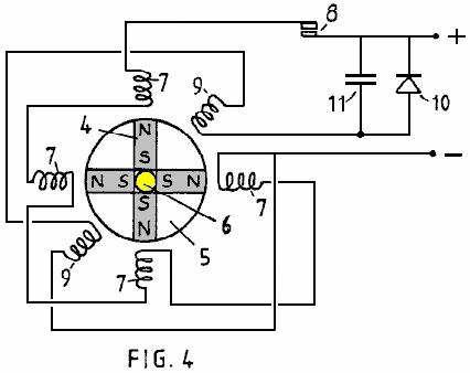
What is shown in Fig.4 is a simple model designed to demonstrate the principle of operation. It comprises a rotor in which four permanent magnets 4 are arrayed to form four poles. The magnets are bonded into four sectors of a non-magnetic disc 5 using a high density polyurethane foam filler and the composite disc is then assembled on a brass spindle 6 between a split flange coupling. Not shown in the figure is the structure holding the spindle vertically in bearings or the star wheel commutator assembly attached to the upper shaft of the spindle.
Note that the magnets present north poles at the perimeter of the rotor disc and that the south poles are held together by being firmly set in the bonding material. A series of four stator poles were formed using magnetic cores from standard electromagnetic relays are were positioned around the rotor disc as shown. The magnetising windings 7 on these cores are shown to be connected in series and powered through commutator contacts 8 by a DC power supply. Two further stator cores formed by similar electromagnetic relay components are depicted by their windings 9 in the intermediate angle positions shown and these are connected in series and connected to a rectifier 10 bridged by a capacitor 11.
The rotor spindle 6 is coupled with a mechanical drive (not shown) which harnesses the torque developed by the motor thus formed and serves as a means for measuring output mechanical power delivered by the machine.
In operation, assuming that the rotor poles are held initially off-register with the corresponding stator poles and the hold is then released, the strong magnetic field action of the permanent magnets will turn the rotor to bring the stator and rotor poles into register. A permanent magnet has a strong attraction for soft iron and so this initial impulse of rotation is powered by the potential energy of the magnets.
Now, with the rotor acting as a flywheel and having inertia it will have a tendency to over-shoot the in-register pole position and that will involve a reverse attraction with the result that the rotor will oscillate until damping action brings it to rest. However, if the contacts of the commutating switch are closed as the poles come
The commutating switch 8 needs only to be closed for a limited period of angular travel following the top dead centre in-register position of the stator and rotor poles. The power supplied through that switch by those pulses will cause the rotor to continue rotating and high speeds will be achieved as the machine develops its full motor function.
Tests on such a machine have shown that more mechanical power can be delivered than is supplied electrically by the source powering the action through the commutating switch. The reason for this is that, whereas the energy in the air gap between rotor and stator poles which is tapped mechanically as the poles come into register is provided by the intrinsic power of the ferromagnet, a demagnetising winding on the part of the core system coupled across that air gap needs very little power to eliminate the mechanical force acting across that air gap. Imagine such a winding on the bridging member shown in Fig.2. The action of current in that winding, which sits astride the 'yawing' flux in that bridging member well removed from the source action of the magnetising windings 1, is placed to be extremely effective in resisting the magnetising influence communicated from a distance. Hence very little power is needed to overcome the magnetic coupling transmitted across the air gap.
Although the mutual inductance between two spaced-apart magnetising windings has a reciprocal action, regardless of which winding is primary and which is secondary, the action in the particular machine situation being described involves the 'solenoidal' contribution represented by the 'yawing' ferromagnetic flux action. The latter is not reciprocal inasmuch as the flux ‘yaw' depends on the geometry of the system. A magnetising winding directing flux directly across an air gap has a different influence on the action in the ferromagnetic core from one directing flux lateral to the air gap and there is no reciprocity in this action.
In any event, the facts of experiment do reveal that, owing to a significant discrepancy in such mutual interaction, more mechanical power is fed into the rotor than is supplied as input from the electrical source.
This has been further demonstrated by using the two stator windings 9 to respond in a generator sense to the passage of the rotor poles. An electrical pulse is induced in each winding by the passage of a rotor pole and this is powered by the inertia of the rotor disc 5. By connecting the power so generated, to charge the capacitor 11, the DC power supply can be augmented to enhance the efficiency even further.
Indeed, the machine is able to demonstrate the excess power delivery from the ferromagnetic system by virtue of electrical power generation charging a battery at a greater rate than a supply battery is discharged.
This invention is concerned with a practical embodiment of the motor-generator principles just described and aims, in its preferred aspect, to provide a robust and reliable machine in which the tooth stresses in the rotor poles, which are fluctuating stresses communicating high reluctance drive torque, are not absorbed by a ceramic permanent magnet liable to rupture owing to its brittle composition.
Another object is to provide a structure which can be dismantled and reassembled easily to replace the permanent magnets, but an even more important object is that of minimising the stray leakage flux oscillations from the powerful permanent magnets. Their rotation in the device depicted in Fig.4 would cause excessive eddy-current induction in nearby metal, including that of the machine itself, and such effects are minimised if the flux changes are confined to paths through steel laminations and if the source flux from the magnets has a symmetry or near symmetry about the axis of rotation.
Thus, the ideal design with this in mind is one where the permanent magnet is a hollow cylinder located on a non-magnetic rotor shaft, but, though that structure is within the scope of this invention, the machine described will utilise several separate permanent magnets approximating, in function, such a cylindrical configuration.
Referring to Fig.4, it will further be noted that the magnetic flux emerging from the north poles will have to find its way along leakage paths through air to re-enter the south poles. For periods in each cycle of machine operation the flux will be attracted through the stator cores, but the passage through air is essential and so the power of the magnets is not used to full advantage and there are those unwanted eddy-current effects.
To overcome this problem the invention provides for two separate rotor sections and the stator poles become bridging members, which with optimum design, allow the flux from the magnets to find a route around a magnetic circuit with minimal leakage through air as the flux is directed through one or other pairs of air gaps where the torque action is developed.
Reference is now made to Fig.5 and the sequence of rotor positions shown. Note that the stator pole width can be significantly smaller that that of the rotor poles. Indeed, for operation using the principles of this invention, it is advantageous for the stator to have a much smaller pole width so as to concentrate the effective pole region. A stator pole width of half that of the rotor is appropriate but it may be even smaller and this has the secondary advantage of requiring smaller magnetising windings and so saving on the loss associated with the current circuit.

The stator has eight pole pieces formed as bridging members 12, more clearly represented in Fig.7, which shows a sectional side view through two rotor sections 13 axially spaced on a rotor shaft 14. There are four permanent magnets 15 positioned between these rotor sections and located in apertures 16 in a disc 17 of a non-magnetic substance of high tensile strength, the latter being shown in Fig.6. The rotor sections are formed from disc laminations of electrical steel which has seven large teeth, the salient poles. Magnetising windings 18 mounted on the bridging members 12 constitute the system governing the action of the motor-generator being described.
The control circuitry is not described as design of such circuitry involves ordinary skill possessed by those involved in the electrical engineering art.
It suffices, therefore, to describe the merits of the structural design configuration of the core elements of the machine. These concern principally the magnetic action and, as can be imagined from Fig.7, the magnetic flux from the magnets enters the rotor laminations by traversing the planar faces of the laminations and being deflected into the plane of the laminations to pass through one or other of the stator pole bridging members, returning by a similar route through the other rotor.
By using eight stator poles and seven rotor poles, the latter having a pole width equal to half the pole pitch in an angular sense, it will be seen from Fig.5, that there is always a flux passage across the small air gap between stator and rotor poles. However, as one pole combination is in-register the diametrically-opposed pole combinations are out-of register.
As described by reference to Fig.4 the operation of the machine involves allowing the magnet to pull stator and rotor poles into register and then, as they separate, pulsing the winding on the relevant stator member to demagnetise that member. In the Fig.4 system, all the stator magnetising windings were pulsed together, which is not an optimum way in which to drive a multi-pole machine.
In the machine having the pole structure with one less rotor pole than stator poles (or an equivalent design in which there is one less stator pole than rotor poles) this pulsing action can be distributed in its demand on the power supply, and though this makes the commutation switch circuit more expensive the resulting benefit outweighs that cost. However, there is a feature of this invention by which that problem can be alleviated if not eliminated.
Suppose that the rotor has the position shown in Fig.5(a) with the rotor pole denoted R1 midway between stator poles S1 and S2 and imagine that this is attracted towards the in-register position with stator pole S2. Upon reaching that in-register position, as shown in Fig.5(c), suppose that the magnetising winding of stator pole S2 is excited by a current pulse which is sustained until the rotor reaches the Fig.5(e) position.
The combination of these two actions will have imparted a forward drive impulse powered by the permanent magnet in the rotor structure and the current pulse which suppresses braking action will have drawn a smaller amount of energy from the electrical power source which supplies it. This is the same process as was described by reference to Fig.4.
However, now consider the events occurring in the rotor action diametrically opposite that just described. In the Fig.5(a) position rotor pole R4 has come fully into register with stator pole S5 and so stator pole S5 is ready to be demagnetised. However, the magnetic coupling between the rotor and stator poles is then at its strongest. Note, however, that in that Fig.5(a) position R5 is beginning its separation from stator poles and the magnetising winding of stator pole S6 must then begin draw power to initiate demagnetisation. During that following period of pole separation the power from the magnet is pulling R1 and S2 together with much more action than is needed to generate that current pulse needed to demagnetise S6. It follows, therefore, that, based on the research findings of the regenerative excitation in the test system of Fig.4, the series connection of the magnetising windings on stators S2 and S6 will, without needing any commutative switching, provide the regenerative power needed for machine operation.
The complementary action of the two magnetising windings during the pole closure and pole separation allows the construction of a machine which, given that the zero-point vacuum energy powering the ferromagnet is feeding input power, will run on that source of energy and thereby cool the sustaining field system.
There are various design options in implementing what has just been proposed. Much depends upon the intended use of the machine. If it is intended to deliver mechanical power output the regenerative electrical power action can all be used to power the demagnetisation with any surplus contributing to a stronger drive torque by reversing the polarity of the stator poles during pole separation.
If the object is to generate electricity by operating in generator mode then one could design a machine having additional windings on the stator for delivering electrical power output. However, it seems preferable to regard the machine as a motor and maximise its efficiency in that capacity whilst using a mechanical coupling to an alternator of conventional design for the electrical power generation function.
In the latter case it would still seem preferable to use the self-excitation feature already described to reduce commutation switching problems.
The question of providing for machine start-up can be addressed by using a separate starter motor powered from an external supply or by providing for current pulsing limited to, say, two stator poles. Thus, for example, with the eight stator pole configuration, the cross-connected magnetising windings could be limited to three stator pairs, with two stator magnetising windings left free for connection to a pulsed external supply source.
If the latter feature were not required, then the stator magnetising windings would all be connected in pairs on a truly diametrically opposite basis. Thus Fig.8 shows a rotor-stator configuration having six stator poles interacting with seven rotor poles and stator magnetising windings linked together in pairs.
The invention, therefore, offers a wide range of implementation possibilities, which, in the light of this disclosure will become obvious to persons skilled in the electrical engineering art, all based, however, on the essential but simple principle that a rotor has a set of poles of common polarity which are attracted into register with a set of stator poles that are suppressed or reversed in polarity magnetically during pole separation. The invention, however, also offers the important feature of minimising commutation and providing further for a magnetic flux closure that minimises the leakage flux and fluctuations of leakage flux and so contributes to efficiency and high torque performance as well as durability and reliability of a machine incorporating the invention.
It is noted that although a machine has been described which uses two rotor sections it is possible to build a composite version of the machine having several rotor sections. In the eventuality that the invention finds use in very large motor-generator machines the problem of providing very large magnets can be overcome by a design in which numerous small magnets are assembled. The structural concept described by reference to Fig.6 in providing locating apertures to house the magnets makes this proposal highly feasible. Furthermore, it is possible to replace the magnets by a steel cylinder and provide a solenoid as part of the stator structure and located between the rotor sections. This would set up an axial magnetic field magnetising the steel cylinder and so polarising the rotor. However, the power supplied to that solenoid would detract from the power generated and so such a machine would not be as effective as the use of permanent magnets such as are now available.
Nevertheless, should one see significant progress in the development of warm superconductor materials, it may become feasible to harness the self-generating motor-generator features of the invention, with its self-cooling properties, by operating the device in an enclosure at low temperatures and replacing the magnets by a superconductive stator supported solenoid.
WILLIAM BARBAT: POWER GENERATOR
Patent Application
SELF-SUSTAINING ELECTRIC POWER GENERATOR UTILISING
ELECTRONS
OF LOW INERTIAL MASS TO MAGNIFY INDUCTIVE ENERGY
This patent application shows a very neat, self-powered electrical generator with a theoretical output of anything up to a COP of 59 when using cadmium selenide. The discussion of the theoretical aspects of the design includes a large amount of historical information and it covers the origin of the “law” of Conservation of Energy which, in spite of being incorrect, has been for decades, a major obstacle to the scientific development of free-energy devices.
Filed: 6th March 2006
Assignee: Levitronics, Inc.
Provisional application No. 60/697,729 filed on 8th July 2005
ABSTRACT
Electrical oscillations in a metallic “sending coil” radiate inductive photons toward one or more “energy-magnifying coils” comprised of a photoconductor or doped semiconductor coating a metallic conductor, or comprised of a superconductor. Electrons of low inertial mass in the energy-magnifying coil(s) receive from the sending coil, a transverse force having no in-line backforce, which exempts this force from the energy-conservation rule. The low-mass electrons in the energy-magnifying coil(s) receive increased acceleration proportional to normal electron mass divided by the lesser mass. Secondarily radiated inductive-photon energy is magnified proportionally to the electrons’ greater acceleration, squared, e.g., the inductive-energy-magnification factor of CdSe photoelectrons with 0.13 x normal electron mass is 59 times. Magnified inductive-photon energy from the energy-magnifying coil(s) induces oscillating electric energy in one or more metallic “output coil(s)”. The electric energy output exceeds the energy input if more of the magnified photon induction energy is directed toward the output coil(s) than is directed as a counter force to the sending coil. After an external energy source initiates the oscillations, feedback from the generated surplus energy makes the device a self-sustaining generator of electric power for useful purposes.
CROSS REFERENCE TO RELATED APPLICATION
This application corresponds to,
and claims the benefit under 35 U.S.C. 119(e), of
FIELD
This disclosure introduces a technical field in which practical electrical energy is created in accordance with the overlooked exception to the energy-conservation rule that Herman von Helmholtz described in his 1847 doctrine on energy conservation: “If . . . bodies possess forces which depend upon time and velocity, or which act in directions other than lines which unite each pair of material points, . . . then combinations of such bodies are possible in which force may be either lost or gained as infinitum”. A transverse inductive force qualifies for Helmholtz’s ad infinitum rule, but this force is not sufficient of itself to cause a greater energy output than input when applied to electrons of normal mass due to their unique charge-to-mass ratio. However, the increased acceleration of conduction electrons of less-then-normal inertial mass, as occurs in photoconductors, doped semiconductors, and superconductors, is proportional to the normal electron mass divided by the low electron mass, and the magnification of harnessable inductive energy is proportional to the square of the greater relative acceleration.
BACKGROUND
Magnetic force also satisfies Helmholtz’s
exemption to the energy-conservation rule because magnetic force is transverse
to the force that causes it, and magnetic force is determined by the “relative
velocity” (i.e. perpendicular to the connecting line) between electric charges. Magnification of magnetic force and energy
was demonstrated by
Applicant has deduced that
Leimer’s energy magnification was most likely due to low-mass electrons that
were liberated and made conductive in the antenna by alpha radiation, which
allowed these special electrons to be given a greater than normal acceleration
by the received radio broadcast photons.
Applicant has further deduced that such low-mass electrons must have
originated in a thin-film coating of cupric oxide (CuO) on the antenna
wire. CuO is a dull black
polycrystalline semiconducting compound that develops in situ on copper and
bronze wire in the course of annealing the wire in the presence of air. Such CuO coatings have been observed by
Applicant on historical laboratory wire at the
The same year that the English
translation of Leimer’s paper appeared in Scientific
American, 16-year old Alfred M. Hubbard of
Newspaper photos (Anon. 1920a) of a more impressive demonstration of Hubbard’s fuelless generator, show a device described as 14 inches (36 cm) long and 11 inches (28 cm) in diameter, connected by four heavy electrical cables to a 35 horsepower (26 kW) electric motor. The motor reportedly propelled an 18-foot open launch around a like at a speed of 8 to 10 knots (Anon. 1920b). The event was witnessed by a cautious news reporter who claims to have checked thoroughly for any wires that might have been connected to hidden batteries, by lifting the device and motor from the boat. Radioactive-decay energy can be eliminated as the main power source because about 108 times more radium than the entire world’s supply would have been needed to equal Hubbard’s reported electric energy output of 330 amperes and 124 volts.
Lester J. Hendershott of
To the Applicant’s best knowledge, the only depiction that was made public of the interior components of any of these reported generators consists of a sketchy drawing (Bermann 1928h) of Hubbard’s apparatus similar in size to the device shown in his 1919 demonstration. It depicts a complex set of parallel coils measuring 6 inches (15 cm) in length and 4.5 inches (11.4 cm) in overall diameter. Four leads of insulated wire, with the insulation peeled back, are shown coming out of the end of the device. What those four wires were connected to internally was not shown. Hubbard’s description of the internal arrangement of coils in the device generally matches the drawing (Anon. 1920a): “It is made up of a group of eight electromagnets, each with primary and secondary windings of copper wire, which are arranged around a large steel core. The core likewise has a single winding. About the entire group of cells is a secondary winding”. Nothing was reported or depicted about how components functioned with each other, or how much radium was used and where the radium was positioned. The only connectors visible on the drawing were between the outer windings of the eight electromagnet coils. These connectors show that the direction of the windings alternated between clockwise and counterclockwise on adjacent coils, so that the polarity of each electromagnet would have been opposite to that of it’s adjacent neighbours.
If the Hubbard and Hendershot devices actually operated as reported, they apparently never attained acceptance or commercial success. Assuming the devices actually worked, their lack of success may have been largely financially or supply based, or both, compounded with scepticism from believers in the energy-conservation doctrine. How much radium was employed by Hubbard in his larger generator can only be guessed at, but assuming a typical laboratory radium needle containing 10 milligrams of radium was used, that amount would have cost $900 in 1920, dropping to $500 in 1929. That much radium in a fuelless generator would have cost as much as an inexpensive automobile in the 1920s. Possibly much more radium was used than 10 milligrams.
In 1922, when the Radium Company
of America of Pittsburgh, Pa., reportedly discontinued its work with Hubbard on
his invention (1928h), the entire world’s supply of radium was only about 250
grams. With the extreme assumption that
only 1 milligram of radium was needed per generator, less than 10% of a single
year’s production of autos in the
Brown claimed an output of 23 amps at 400 volts, which is vastly greater than all the decay energy represented by his reported radioactive content of 1 milligram of radium that was surrounded by weakly radioactive uranium rods and thorium powder. Powered thorium is highly pyrophoric, so it is typically sealed in a nitrogen atmosphere to prevent spontaneous combustion. In his device, Brown reportedly confined the thorium in cardboard without any mention of sealing out air. This condition would have invited a meltdown that could have been interpreted as massive out-of-control electrical production.
To the best of the Applicant’s knowledge, no person other than the Applicant has ever indicated that the presence of cupric oxide on their wires could have provided energy magnification. If Hubbard’s device actually did work, certain characteristics of its design are unexplainable by the Applicant, namely the use of four rather than two large electrical cables to connect his device to an electrical motor, and the use of alternating polarity instead of single-direction polarity in the orientation of the multiple coils surrounding a central coil. Applicant therefore believes that the specification herein sets forth original configurations of electrical-energy generators that have no known precedent.
SUMMARY
To address the needs for electrical generators which are capable of self-generating substantial amounts of electrical power in various environments, and which are portable as well as stationary, apparatus and methods are provided for magnifying an electrical input, and (with feedback) for generating usable electrical power indefinitely without fuel or other external energy source, except for starting. The apparatus utilises electrons of low effective mass, which receive greater acceleration than normal electrons in an amount that is inversely proportional to the effective mass. Applicant has determined that effective mass is the same as the electron’s true inertial mass. The photon energy that is radiated when an electron is accelerated is proportional to the square of the acceleration, so the increase in radiated photon energy from an accelerated low-mass electron over the energy from a normal electron is equal to the inverse square of the effective mass, e.g. the calculated energy magnification provided by photoconducting electrons in cadmium selenide, with an electron effective mass of 0.13, is 59 times. The use of a transverse force, that lacks a direct back-force, to accelerate low-mass electrons in an oscillating manner, circumvents any equal-and-opposite force that would invoke the application of the energy-conservation law of kinetics and thermodynamics.
The various embodiments of the apparatus, which are configured either to continuously magnify an input of oscillating electric energy, or to serve as a self-sustaining electric generator, employ three principal components:
At least one
sending coil
At least one energy-magnification coil, comprising a material that produces , in a “condition” low-mass electrons, and
At least one output coil.
It is desirable that the apparatus also includes a means for establishing the condition with respect to the energy-magnifying coil(s). Except where otherwise indicated in the remainder of this text, where the number of coils of a particular type is referred to in the singular, it will be understood that a plurality of coils of the respective type can alternatively be utilised.
Electrical oscillation in the sending coil, which is comprised of a metallic conductor, causes radiation of inductive photons from the sending coil. The energy-magnifying coil is situated in a position relative to the sending coil so as to receive inductive photons from the sending coil. The inductive photons radiating from electrical oscillations in the sending coil, convey a transverse force to the low-mass electrons in the energy-magnification coil with no back-force on the sending coil. The greater-than-normal accelerations which are produced in the low-mass electrons of the energy-magnifying coil, produce greater irradiation energy of inductive photons than normal.
The output coil is positioned so as to receive the magnified inductive-photon energy from the energy-magnifying coil. The inductive-photon energy received by the output coil, which is comprised of a metallic conductor, is converted into an oscillating electrical current of normal electrons. In order for the electrical output to exceed the electrical input, the output coil is situated in such a manner that it receives more of the magnified inductive-photon energy than that which is directed back against the sending coil to act as a back-force. This “energy leverage” causes the electrical energy output to exceed the electrical energy input.
By way of example, the energy-magnifying coil can comprise a superconducting material, wherein the “condition” is a temperature (e.g. a cryogenic temperature) at which the superconducting material exhibits superconducting behaviour characterised by production of low-mass electrons.
By way of another example, the energy-magnifying coil can comprise a photoconductive material, wherein the “condition” is a situation in which the photoconductive material is illuminated by a wavelength of photon radiation sufficient to cause the photoconductive material of the energy-magnifying coil to produce conduction electrons having low effective mass. In this latter example, the means for establishing the condition can comprise a photoconductor exciter (e.g. one or more LEDs) situated and configured to illuminate the photoconductive material of the energy-magnifying coil with the wavelength of photon radiation.
By way of yet another example, the “condition” is the presence of a particular dopant in a semiconductor that provides a low-mass electron as a charge carrier. Also, by way of example, the energy-magnifying coil can comprise a semiconductive element or compound that has been doped with a particular element or compound that makes it conductive of low-mass electrons without illumination by photon radiation other than by ambient photons.
Various apparatus embodiments comprise different respective numbers and arrangements of the principal components. The various embodiments additionally can comprise one or more of circuitry, energisers, shielding and other components to fulfill the object of providing a self-sustaining source of electrical power for useful purposes.
Also provided, are methods for generating an electrical current. In an embodiment of such a method, a first coil is energised with an electrical oscillation sufficient to cause the first coil to radiate inductive photons. At least some of the radiated inductive photons from the first coil are received by a second coil, called “the energy-magnifying coil”, comprising a material that produces low-mass electrons. The received inductive photons impart respective transverse forces to the low-mass electrons that cause the low-mass electrons to experience accelerations in the material which are greater than accelerations that otherwise would be experienced by normal free electrons experiencing the transverse forces.
Conduction of the accelerated low-mass electrons in the second coil, causes the second coil to produce a magnified inductive force. The magnified inductive force is received by a third coil which causes the third coil to produce an oscillating electrical output of normal conduction electrons which has greater energy than the initial oscillation. A portion of the oscillating electrical output is directed as feed-back from the third coil to the sending coil, so as to provide the electrical oscillation to the sending coil. This portion of the oscillating electrical current directed to the sending coil, desirably is sufficient to cause self-sustaining generation of inductive photons by the first coil without the need for any external energy source. The surplus oscillating electrical output from the third coil can be directed to a work loop.
The method can further comprise the step of starting the energisation of the first coil to commence generation of the oscillating electrical output. This “starting” step can comprise momentarily exposing the first coil to an external oscillating inductive force or for example, to an external magnetic force which initiates an electrical pulse.
The foregoing and additional features and advantages of the invention will be more readily apparent from the following detailed description, which proceeds with reference to the accompanying drawings.
BRIEF
DESCRIPTION OF THE DRAWINGS
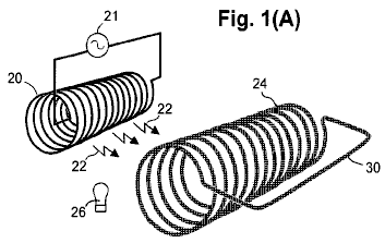
Fig.1A is a perspective view schematically depicting a sending coil in relationship to an energy-magnifying coil such that inductive photons from the sending coil, propagate to the energy-magnifying coil.
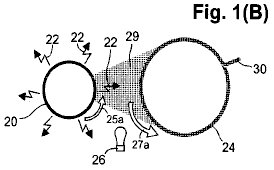
Fig.1B is a schematic end-view of the sending coil and energy-magnifying coil of Fig.1A, further depicting radiation of inductive photons from the sending coil and the respective directions of electron flow in the coils.
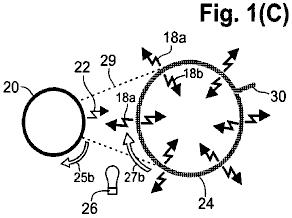
Fig.1C is a schematic end-view of the sending coil and energy-magnifying coil of Fig.1A, further depicting the production of inwardly-radiating and outwardly-radiating magnified inductive photons from the energy-magnifying coil.

Fig.2A is a perspective view schematically showing an internal output coil, coaxially nested inside the energy-magnifying coil to allow efficient induction of the internal output coil by the energy-magnifying coil, wherein the induction current established in the internal output coil is used to power a load connected across the internal output coil.
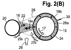
Fig.2B is a schematic end-view of the coils shown in Fig.2A, further depicting the greater amount of magnified inductive-photon radiation that is received by the external output coil in comparison to the lesser amount that is directed toward the sending coil to act as a back-force.
Fig.3 is an electrical schematic diagram of a representative embodiment of a generating apparatus.
Fig.4 is a schematic end-view of a representative embodiment, comprising a centrally disposed sending coil surrounded by six energy-magnifying coils, each having and axis which is substantially parallel to the axis of the sending coil. A respective internal output coil is coaxially nested inside each energy-magnifying coil, and the energy-magnifying coils are arranged so as to capture substantially all the inductive photons radiating from the sending coil.
Fig.5 is a schematic end-view of the embodiment of Fig.4, further including an external output coil situated coaxially with the sending coil and configured to surround all six energy-magnifying coils so as to capture outwardly-radiating inductive photons from the energy-magnifying coils. Also depicted is the greater amount of magnified inductive-photon radiation that is received by the internal output coils and the external output coil in comparison to the lesser amount of inductive-photon radiation that is directed towards the sending coil to act as a back-force. Also shown are the arrays of LEDs used for exciting the energy-magnifying coils to become photoconductive.
Fig.6 is a perspective view of the embodiment of Fig.4 and Fig.5 but further depicting respective inter-coil connections for the energy-magnifying and internal output coils, as well as respective leads for the sending coil, internal output coils and external output coil.
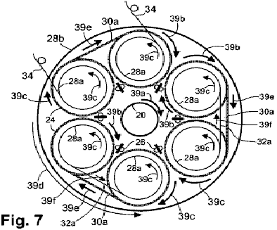
Fig.7 is a head-end view schematically depicting exemplary current-flow directions in the sending coil, energy-magnifying coils, internal output coils, and external output coils, as well as in the various inter-coil connections of the embodiment of Fig.4.
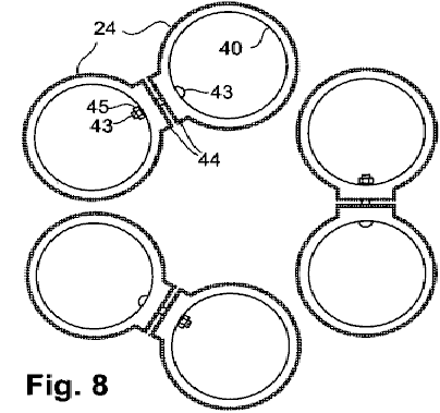
Fig.8 is a schematic end-view showing an embodiment of the manner in which inter-coil connections can be made between adjacent energy-magnifying coils.
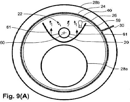
Fig.9A is a schematic end-view depicting the coil configuration of an embodiment in which a sending coil and an internal output coil are nested inside an energy-magnifying coil, which in turn is nested inside an exterior output coil. A metallic separator, having a substantially parabolic shape, and being situated between the sending coil and the internal output coil, reflects some of the otherwise unused inductive-photon radiation to maximise the effective radiation received by the energy-magnifying coil. Also, the metallic shield prevents the internal output coil from receiving radiation sent from the sending coil.
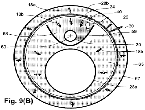
Fig.9B is a schematic end-view of the coil configuration of Fig.9A, further depicting the metallic separator acting as a shield to restrict the back-force radiation reaching the sending coil while allowing the internal output coil to receive a substantial portion of the magnified radiation from the energy-magnifying coil. Also depicted is the greater amount of magnified inductive-photon radiation that is received by the internal output coil and the external output coil in comparison to the lesser amount that is received by the sending coil to act as a back-force.

Fig10A is a schematic end-view depicting the coil configuration of yet another embodiment that is similar in some respects to the embodiment of Fig.4, but also including respective ferromagnetic cores inside the sending coil and internal output coils. Also depicted is a metallic shield surrounding the entire apparatus.
Fig.10B is a schematic end-view of a sending coil of yet another embodiment in which a ferromagnetic sleeve is disposed coaxially around the sending coil.
DETAILED DESCRIPTION
General Technical
Considerations
An understanding of how “infinite energy” mistakenly came to be rejected by the scientific community, clarifies the basis of this invention. The electrodynamic function described in the embodiments described below, conforms to Helmholtz’s alternate energy rule, which states that a force which is not in line with it’s causative force “may be lost or gained ad infinitum”. This rule was included in “Uber die Erhaltung der Kraft” (“On the Conservation of Force”) that Hermann Helmholtz delivered to the Physical Society of Berlin in 1847. But, Helmholtz mistakenly believed that “all actions in nature are reducible to forces of attraction and repulsion, the intensity of the forces depending solely upon the distances between the points involved .... so it is impossible to obtain an unlimited amount of force capable of doing work as the result of any combination whatsoever of natural objects”.
Helmholtz refused to accept the idea that magnetic energy qualifies for ad infinitum status despite the fact that Ampere’s (1820) magnetic force on parallel straight conductors is obviously transverse to the direction of the electric currents rather than being in line with the currents. He omitted mention that the magnetic force in Ampere’s (1825) important invention, the solenoidal electromagnet, is caused by currents in the loops of his coils, which are transverse to the direction of magnetic force. Also, he failed to mention that Ampere considered the magnetic force of a permanent magnet to be caused by minute transverse circular currents, which are now recognised as electrons that spin and orbit transversely.
Helmholtz, who was educated as a military medical doctor without any formal study of physics, relied instead on an obsolete metaphysical explanation of magnetic force: “Magnetic attraction may be deduced completely from the assumption of two fluids which attract or repel in the inverse ratio of the square of their distance....It is known that the external effects of a magnet can always be represented by a certain distribution of the magnetic fluids on its surface”. Without departing from this belief in magnetic fluids, Helmholtz cited Wilhelm Weber’s (1846) similarly wrong interpretation that magnetic and inductive forces are directed in the same line as that between the moving electric charges which cause the forces.
Weber had thought that he could unify Coulombic, magnetic, and inductive forces in a single, simple equation, but Weber’s flawed magnetic-force term leads to the absurd conclusion that a steady current in a straight wire induces a steady electric current in a parallel wire. Also, a changing current does not induce an electromotive force in line with the current, as Weber’s equation showed. The induced force is offset instead, which becomes more apparent the further that two nested, coaxial coils are separated. What appears to be a directly opposing back-force is actually a reciprocal inductive force.
Helmholtz’s assertion that the total sum of the energy in the universe is a fixed amount that is immutable in quantity from eternity to eternity appealed to his young friends. But, the elder scientists of the Physical Society of Berlin declared his paper to be “fantastical speculation” and a “hazardous leap into very speculative metaphysics”, so it was rejected for publication in Annalen der Physik. Rather than accept this rejection constructively, Helmholtz found a printer willing to help him self-publish his work. Helmholtz headed the publication with a statement that his paper had been read before the Society, but he disingenuously withheld mention of its outright rejection. Unwary readers have since received the wrong impression that his universal energy-conservation rule had received the Society’s endorsement rather than its censure.
Helmholtz (1862, 1863) publicised
his concept thus: “We have been led up to a universal natural law, which ...
expresses a perfectly general and particularly characteristic property of all
natural forces, and which ... is to be placed by the side of the laws of the
unalterability of mass and the unalterability of the chemical elements”. Helmholtz (1881) declared that any force that
did not conserve energy would be “in contradiction to
Ampere’s principle of transverse magnetic attraction and repulsion between electric currents had been made into an equation for the magnetic force between moving electric charges by Carl Fredrick Gauss (written in 1835, published posthumously in 1865). The critical part of the Gauss equation shows, and modern physics texts agree, that magnetic force is transverse to the force that imparts a relative velocity (i.e. perpendicular to a connecting line) between charges. Lacking a direct back-force, a transverse magnetic force can produce a greater force than the force that causes it.
The only physicist to recognise in print, the profound significance of the work of Gauss, was James Clerk Maxwell (1873), who stated “(If Gauss’s formula is correct), energy might be generated indefinitely in a finite system by physical means”. Prepossessed with Helmholtz’s “law”, Maxwell chose not to believe Gauss’s transverse magnetic-force equation and accepted Wilhelm Weber’s (1846) erroneous in-line formula instead. Maxwell even admitted knowing of Gauss’s (1845) rebuke of Weber for his mistaken direction of magnetic force as “a complete overthrow of Ampere’s fundamental formula and the adoption of essential a different one”.
In 1893, the critical part of Ampere’s formula for magnetic force, which Weber and Maxwell rejected, and which Helmholtz had replaced with his contrary metaphysical explanation, was proposed for the basis for the international measure of electric current, the Ampere (or amp), to be defined in terms of the transverse magnetic force which the current produces. But Helmholtz’s doctrine had become so impervious to facts that anyone who challenged this “law” faced defamation and ridicule.
The first recognition of unlimited energy came from Sir Joseph Larmor who reported in 1897, “A single ion e, describing an elliptic orbit under an attraction to a fixed centre ... must rapidly lose its energy by radiation ... but in the cases of steady motion, it is just this amount that is needed to maintain the permanency of motion in the aether”. Apparently to mollify critics of his heretical concept, Larmor offered a half-hearted recantation in 1900: “The energy of orbital groups ... would be through time, sensibly dissipated by radiation, so that such groups could not be permanent”.
In 1911,
Niels Bohr (1924) was bothered by the notion that radiation from an orbiting electron would quickly drain its energy so that the electron should spiral into the nucleus. Whittaker (1951) states, “Bohr and associates abandoned the principle ... that an atom which is emitting or absorbing radiation must be losing or gaining energy. In its place, they introduced the notion or virtual radiation, which was propagated in ... waves but which does not transmit energy or momentum”. Subsequently, the entire scientific community dismissed Larmor radiation as a source of real energy because it failed to conform to Helmholtz’s universally accepted doctrine.
Helmholtz’s constraining idea that the vast amount of light and heat radiating from the many billions of stars in the universe can only come from previously stored energy, has led scientists to concur that fusion of pre-existing hydrogen to helium, supplies nearly all the energy that causes light and heat to radiate from the sun and other starts. If so, then the entire universe will become completely dark after the present hydrogen supply in stars is consumed in about 20 billion years. William A. Fowler (1965) believed that essentially all the hydrogen in the universe “emerged from the first few minutes of the early high-temperature, high-density stage of the expanding Universe, the so-called ‘big bang’ ...” Moreover, the background energy of the universe was thought by some to be “relic” radiation from the “Big Bang”.
To accept the Big Bang idea that all the stars in the universe originated at the same time, it was necessary to disregard the fact that most stars are much younger or much older than the supposed age of the one-time event, which indicates that their energy must have come from a recurring source. The Big Bang is entirely dependent on the idea that the whole universe is expanding, which stemmed from the interpretation that Hubble’s red-shift with distance from the light source, represents a Doppler shift of receding stars and galaxies. This expanding-universe interpretation was shattered by William G. Tifft (1976, 1977), who found that observed red-shifts are not spread randomly and smoothly over a range of values, as would be expected from the Doppler shifts of a vast number of receding stars and galaxies. Instead, the observed red-shifts all fall on evenly spaced, quantised values.
Moreover, Shpenkov and Kreidik (2002) determined that the radiation temperature corresponding to the fundamental period of the orbital electron motion in the hydrogen atom of 2.72890K matches the measured temperature of cosmic background radiation of 2.7250K plus or minus 0.0020K. This represents perpetual zero-level Larmor radiation from interstellar hydrogen atoms dispersed in the universe. So, Helmholtz’s idea that “the energy in the universe is a fixed amount immutable in quantity from eternity to eternity” does not stand up to known facts.
The large aggregate quantity of
heat-photons which is generated continually by Larmor radiation can account for
the illumination of stars and for the enormous heat and pressure in active
galactic centres. Based on the fact that
photons exhibit momentum, photons must posses mass, because, as
Another principle that is important to this specification, is that the transfer of energy by electrical induction was found by the Applicant to work in the same manner as the transfer of energy by broadcast and reception of oscillating radio signals. A transverse force is communicated in both cases, the force declines similarly with distance, and the effects of shielding and reflection are identical. Since radio signals are communicated by photons, Applicant considers that inductive force is also communicated by photons. The radiation of newly formed inductive photons results when an accelerated charge experiences a change in direction of acceleration. Inductive radiation occurs when the acceleration of electric charges is reversed, as in Rontgen’s bremsstrahlung, in Hertz’s linear oscillator (plus all other radio-broadcasting antennas), and in coils which carry an alternating current.
In a similar case, when electric charges move in a curving motion due to a continually changing centripetal acceleration, inductive photons are radiated steadily. This includes the radiation from electrons orbiting atomic nuclei (Larmor radiation) and from conduction electrons flowing in a wire coil, whether the current is steady or not. Circularly produced inductive photons induce a circular motion (diamagnetism) in mobile electrons located near the axis of the electron’s circular movement.
In both the reverse-acceleration and centripetal-acceleration cases, inductive photons convey a force to mobile electrons that is transverse to the photon’s propagation path. As Lapp and Andrews (1954) reported, “Low-energy photons produce photoelectrons at right angles to their path ...”. This same right-angle force without a direct back-force, applies as well, to all conduction electrons which are accelerated by low-energy photons. Hence, inductive energy qualifies for exemption from the energy-conservation law by Helmholtz’s same ad infinitum principle which exempts magnetic energy.
The transverse force that inductively produced photons delivered to mobile electrons, is opposite in direction to the simultaneous movement of the primary charge which produces the radiation. This is shown by Faraday’s induced current opposite to the inducing current and by the diamagnetically-induced circular motion which, in a rotational sense, is opposite to the circular electron motion in the coil producing it. An oscillating flow of electrons within a loop of a wire coil, induces a force on the conduction electrons which is in the opposite direction in adjacent loops of the same wire. This results in self-induction.
Important to this specification is the realisation that the energy transmitted by photons is kinetic rather than electromagnetic. Inductively radiated photons of low energy, light rays and X-rays cannot be deflected by and electric or magnetic field due to the photons’ neutral charge. Neither do neutral photons carry an electric or magnetic field with them. Photon radiation is produced by a change in the acceleration of an electric charge, so only in special cases does it have an electrokinetic origin which involves a magnetic force. To honour these facts, Applicant uses the term “electrokinetic spectrum” in place of “electromagnetic spectrum”.
Another principle which is important to this specification is the realisation that, although the charge on the electron has a constant value under all conditions, the mass of an electron is not a fixed, unchanging amount. All free electrons, as in cathode rays, have exactly the same amount of mass at sub-relativistic velocities. This is called “normal” mass and is denoted by me. Free electrons have a unique charge to mass ratio that makes the magnetic force resulting from a sub-relativistic velocity imparted to such an electron, exactly equal to the energy input with “normal” electrons.
Also, when a normal electron is given a sub-relativistic acceleration, the inductive force it produces is equal to the force it receives. The mass of highly conductive electrons of metals is apparently very close to normal, but any very slight inductive-energy gains would be masked by inefficiencies. The ubiquity of free electrons and the conduction electrons of metals has led to the view that electron mass is a never-varying figure that would allow the energy conservation law to apply to magnetic energy and inductive energy.
Accurate determinations of electron mass in solid materials have been made possible by cyclotron resonance, which is also called diamagnetic resonance. The diamagnetic force produced by the steady flow of electrons in a wire coil, induces the mobile electrons of a semiconductor to move in a circular orbit of indefinite radius but at a definite angular frequency. This frequency is only related to the inductive force and the mass of the electron. At the same time, a repulsive magnetic force is developed by the relative velocity between the electron flow in the coil and the conduction electrons, causing the mobile electrons of the semiconductor to move in a helical path away from the coil rather than in planar circles. Only two measurements are needed to determine the mass of such an electron: the cyclotron frequency which resonates with the frequency of the electron’s circular motion, and the strength of the inductive force, which is determined by the current and dimensions of the coil. Since the co-produced magnetic field is related to the same parameters, its measurement serves as a surrogate for inductive force.
Because the measured mass of conduction electrons in semiconductors is less than normal, a complicated explanation has been adopted to defend the constancy of electron mass in order to support Helmholtz’s energy doctrine. An extra force is supposedly received from the vibrational lattice-wave energy of the crystal (in what would have to be an act of self-refrigeration) to make normal-mass electrons move faster than expected around a circular path, thereby giving the appearance that the electron has less mass than normal. In this explanation, the electron is considered to be a smeared-out wave rather than a particle, which is contradicted by the billiard-ball-like recoil of an electron when it is bumped by a quantum of radiation, as described by Arthur Crompton and Samuel Allison (1935).
The fallacy that borrowed energy can provide a boost in velocity to an electron, is more apparent in the case of linear motion. The effective-mass theory considers that the greater linear velocity is caused by a boost given to normal-mass electrons by a “longitudinal wave” imparted by an externally applied force in the same direction as the electron motion. Since this longitudinal wave is also considered to have a source in crystal-lattice vibrations, the effective-mass theory relies on a reversal of entropy in violation of the second Law of Thermodynamics.
No reasonable contribution of direct directional energy can be invoked from any source to impart abnormally great velocity to the conduction electrons in semiconductors. So, the operation of apparatus embodiments described herein, relies on electrons having particle properties and on electrons having less-then-normal inertial mass without invoking any special forces. This is supported by Brennan’s (1999) statement that “the complicated problem of an electron moving within a crystal under the interaction of a periodic but complicated potential, can be reduced to that of a simple free particle, but with a modified mass”. The term “effective” is herein considered redundant in referring to truly inertial mass, but “effective mass” still has relevance in referring to the net movement of orbital vacancies or “holes” in the opposite direction of low-mass electrons.
By F = ma, a low-mass electron receives greater acceleration and greater velocity from a given force than an electron of normal mass. The velocity and kinetic energy imparted to an electrically charged body by a force, are determined by the electric charge without regard to the body’s mass. Having a smaller amount of mass, allows a body to attain a greater velocity with any given force. Hence, the magnetic force produced by the charge at this higher velocity will be greater than it would normally be for that same amount of force. This allows low-mass electrons to produce a magnetic force that is greater than the applied force.
Also, the amount of inductive radiation energy from accelerated electrons is related to an electron’s charge without regard to its mass. The energy of inductive radiation increases with the square of the electron’s acceleration according to Larmor’s (1900) equation, while the acceleration is inversely proportional to the lesser electron mass relative to normal electron mass. Therefore, the greater-than-normal acceleration of low-mass electrons, allows the re-radiation of magnified inductive-photon energy at a magnification factor which is proportional to the inverse square of the electron’s mass, e.g., the inductive-energy magnification factor of cadmium selenide photoelectrons with 0.13 of the normal electron mass is (0.13)2 which is 59 times.
Electrons appear to acquire or shed mass from photons in order to fit the constraints of particular orbits around nuclei, because each orbit dictates a very specific electron mass. In metals, where the conduction electrons seem to move as would a gas, one might think that they would assume the normal mass of free electrons. But the largest mean free path of electrons in the most conductive metals is reportedly about 100 atomic spacings between collisions (Pops, 1997), so the conduction electrons apparently fall back into orbit from time to time and thereby regain their metal-specific mass values.
As conduction electrons pass from one metal type to another, they either lose or gain heat-photons to adjust their mass to different orbital constraints. In a circuit comprising two different metallic conductors placed in series contact with each other, the flow of conduction electrons in one direction will cause the emission of heat-photons at the junction, while an electron flow in the reverse direction causes cooling as the result of ambient heat-photons being absorbed by the conduction electrons at the junction (Peltier cooling effect). When a metal is joined with a semiconductor whose conductive electrons have much lower mass than in metals, much greater heating or cooling occurs at their junction.
John Bardeen (1941) reported that the (effective) mass of superconducting electrons in low-temperature superconductors is only 10-4 as great as the mass of normal electrons. This is demonstrated when superconducting electrons are accelerated to a much higher circular velocity than normal in diamagnetically induced eddy currents, which results in enormous magnetic forces which are capable of levitating heavy magnetic objects. Electrons with 10-4 times normal mass are apparently devoid, (or nearly devoid) of included photon mass, so normal electrons are deduced to posses about 104 times more included photon mass than the bare electron’s own mass.
The means by which photon mass may be incorporated within, or ejected from electrons, can be deduced from known information. Based on the Thompson scattering cross-section, the classical radius of a normal electron is 2 x 10-15 cm. If the electron has uniform charge throughout a sphere of that radius, the peripheral velocity would greatly exceed the velocity of light in order to provide the observed magnetic moment. Dehmelt (1989) determined that the radius of the spinning charge which creates an electron’s magnetism, is approximately 10-20 cm. This apparent incongruity can be explained if the electron is considered to be a hollow shell (which is commensurate with the bare electron’s tiny mass in comparison to the very large radius) and if the negative charge of the shell is not the source of the magnetic moment.
It has long been known that a photon can be split into an negative ion (electron) and a positive ion (positron), each having the same amount of charge but of opposite sign. Electrons and positrons can recombine into electrically neutral photons, so it is apparent that photons are composed of a positive and a negative ion. Two ions spinning around each other could produce the photon’s wave nature. The only size of photon ion that can exist as a separate entity has a charge of exactly plus one or minus one, whereas the ions can have a very much larger or very much smaller charge and mass when combined in photons, as long as the two ions are equal in charge and mass. Combined in a photon, the two ions are apparently attracted together so strongly that their individual volumes are very much smaller than as separate entities.
When a dipole photon enters an electron shell, its negative-ion portion is expected to be forced towards the shell’s centre by Coulombic repulsion, while the photon’s positive ion would be attracted by the negative charge of the shell equally in all directions. The negative photon ions would likely merge into a single body at the electron’s centre, while the positive-ion portion would orbit around the centralised negative ion to retain the photon’s angular momentum. The high peripheral velocity of this orbiting photon mass would enable portions of photon material to spin off and exit the electron shell at the same velocity at which they entered the electron, i.e., the speed of light. The orbiting of the positive photon charge at Dehmelt’s small radius, most likely accounts for the magnetic moment that is observed in electrons of normal mass.
Liberated low-mass conduction electrons within intrinsic semiconductors (which are also photoconductors by their nature) and within doped semiconductors, are mostly protected against acquiring mass from ambient-heat photons by the heat-insulative properties of the semiconductors. In contrast, low-mass electrons injected into heat-conducting metals, rapidly acquire mass from ambient-heat photons by the existence of cryogenic conditions, but they are vulnerable to internal heat-photons created by excessive induction.
Conduction electrons of metals, typically move as a group at drift velocities of less than one millimetre per second, although the velocity of the electrical effects approaches the velocity of light. (Photons are probably involved in the movement of electrical energy in metallic conductors.) In contrast, conductive low-mass electrons can move individually at great velocities in superconductors and semiconductors. Brennan (1999, p. 631) reports the drift velocity of a particular electron moving in a semiconductor, to be one micrometer in about 10 picoseconds, which is equivalent to 100 kilometers per second.
The concentration of the conduction electrons in metals is the same as the number of atoms, whereas in semiconductors, the mobile low-mass electrons which are free to move, can vary greatly with the amount of certain photon radiation received. Since the magnitude of an electric current is a summation of the number of electrons involved, times their respective drift velocities, the current developed by a small ensemble of photoconducting electrons moving at high speed, can exceed the current of a much greater number of conduction electrons moving at a very low speed in a metal.
A general feature of intrinsic semiconductors is that they become photoconductive in proportion to the amount of bombardment by some particular electron-liberating frequency (or band of frequencies) of photon energy, up to some limit. The amount of bombardment by the particular wavelength (or, equivalently, the frequency), increases along with all other photon wavelengths as the ambient temperature rises, that is, as the area under Planck’s black-body radiation curve increases. Consequently, the conductivity of semiconductors continues to increase with temperature, while the conductivity drops to almost zero at low temperature unless superconductivity occurs.
A single high-energy alpha particle can liberate a great number of low-mass electrons in a thin-film semiconductor, as Leimer’s (1915) energy-magnifying experiment appears to show. Leimer’s alpha radiation was situated near the distant end of a suspended antenna wire of unreported length, when he experienced the maximum magnetic energy increase in the coil of the ammeter in the receiver. The low-mass electrons had to have travelled the entire length of the suspended antenna and the connecting line to his receiving apparatus without encountering any trapping holes. Assuming these electrons traversed a distance of 1 to 10 metres in less than one half-cycle of the radio frequency, (that is, less than 4 microseconds at 128 kHz) at which time the direction of the low-mass electron would have been reversed, this would be equivalent to velocities of 25 to 250 km/sec.
A great number of superconducting electrons can be set in motion by inductive photon radiation. In contrast, inductive photon radiation can pass mostly through photoconductors that have low concentrations of mobile, low-mass electrons. Applicant’s interpretation of Leimer’s experiment is that the liberated low-mass electrons of the semiconductor coating of the antenna wire, were not directly accelerated by the inductive photons of the radio signal, but rather were accelerated to high velocities by an oscillating electric field created in the metallic wire by the radio photons.
A review of an experiment performed by File and Mills (1963), shows that the very low mass of superconducting electrons is responsible for causing supercurrents to differ from normal electric currents. A superconducting solenoidal coil (comprising a Nb-25% Zr alloy wire below 4.30 K.) with the terminals spot-welded together to make a continuous conductor, was employed. Extremely slow declines of induced supercurrents were observed, which can be attributed to an enormous increase in the coil’s self-induction. Because a supercurrent approaches its maximum charge asymptotically when discharging, a convenient measure of the coil’s charging or discharging rate is the “time-constant”. The time-constant has the same value for both charging and discharging, and it is defined as (a) the time needed for charging the coil to 63% of the maximum amount of current inducible in the coil by a given diamagnetic force, or (b) the time needed to discharge 63% of the coil’s induced current.
In normal conductors, the inductive time-constant is calculated by the inductance of the coil, divided by the resistance of the coil. By use of an empirical equation, the inductance of the coil in its non-superconducting state is calculated to be 0,34 Henry, based on a double-layered solenoid of 384 turns that measured 4 inches (10 cm) diameter and 10 inches (25 cm) long. The resistance of the 0.020 inch (0.51 mm) diameter wire at a temperature of 50 K. (just above Tc) is estimated by using data for Zr alone, to be 4 x 10² ohms. (Resistivity data were not available for Nb or the subject alloy). Under non-superconducting conditions, the time-constant for charging and discharging this coil is thereby calculated to be approximately 8 x 10⁻⁵ sec.
The time it took to charge up a supercurrent in the coil in the experiment was not reported. But, based on the reported 50 re-energisings and magnetic determinations performed in 200 hours, the measured charging time in the superconducting state is computed to be no more than 4 hours on average.
Using Bardeen’s (1941) formula of m is approximately equal to me times 10-4 for the order of magnitude of the low Tc superconducting electron’s mass, and using Larmor’s equation (1900) which relates inductive radiation power to the square of the acceleration of the charge, the inductance of the coil is expected to increase by (104)2 = 108 times in the superconducting state. Thus, the calculated increase in the time-constant of charging up the supercurrent is 8 x 10-5 x 108 which equals 8 x 10³ seconds, or 2.2 hours, which is the same order of magnitude as the maximum actual charging time. The self-induction increased by that amount because the low-mass electrons are accelerated 104 times faster.
In the case of discharging, the time constant of the supercurrent was projected by File and Mills from measured declines observed over periods of 21 and 37 days. The projections of the two 63% declines agreed closely at 4 x 10¹² seconds (= 1.3 x 10⁵ years). Therefore, the time-constant of supercurrent discharge, based on projecting actual measurements, had increased by 5 x 10¹⁶ times over the time-constant for electrons of normal mass.
The driving force during charging, had been the applied inductive force, whereas the driving force during discharging was the supercurrent that had been magnified 108 times. Therefore, during the discharging of the supercurrent, the time-constant is increased again by 108 times, so the calculated total increase in the time-constant of discharge is 108 x 108 = 1016 times greater than the normal time-constant. This calculated value of the non-superconducting time-constant, based solely on the increase of inductive radiation due to extremely low electron mass, compares favourably in magnitude with the actually observed value of 5 x 10¹⁶ times the normal time-constant.
The superconducting coil required no more than four hours to charge up the supercurrent, yet during subsequent discharge, the superconducting coil was projected to radiate inductive photon energy from the centripetal acceleration of the superconducting electrons for 130,000 years before declining by 63%. If this experiment could take place where no energy would needed to sustain critical cryogenic conditions, as in outer space, the lengthy discharge of this energised coil would clearly demonstrate the creation of energy in the form of newly-created photons inductively radiating from the superconducting low-mass electrons that circulate around the coil’s loops. Applicant interprets this as showing that low-mass electrons are capable of inductive-energy-magnification based solely on their mass relative to that of normal electrons.
In the embodiments described below, the magnified inductive energy of low-mass electrons is utilised in coils for electric-energy generation by employing a flow of inductively accelerated photons that alternates in direction. This, in turn, drives low-mass electrons in an oscillating manner, so this forced reversal involves only a single stage of inductive-energy magnification, rather than the two stages (charging and naturally discharging) in the foregoing experiment.
Mode of
Operation
Inductive photons radiating from an oscillating electric current in a sending conductor (e.g. from a radio-wave broadcasting antenna) convey a force, on conduction electrons in a receiving conductor, that is transverse to the incidence direction of the incident inductive photons on the receiving conductor. As a result, no back-force is transferred directly back to the sending conductor. Applicant has discovered that the action of this transverse force on low-mass electrons in a receiving conductor is analogous to the action of Gauss’s transverse magnetic force on free electrons in a conductor, which is not subject to the kinetics law of conservation of energy. If the receiving conductor has low-mass conduction electrons, then this transverse force would impart greater acceleration to the low-mass electrons than that it would impart to normal free electrons. The resulting greater drift velocities of low-mass electrons than normal free electrons in the receiving conductor, would yield an increased magnitude of inductive force produced by the low-mass electrons in the receiving conductor and hence produce a magnification of the irradiation energy of inductive photons.
The direction of the transverse force imparted by the radiated inductive photons on conduction electrons in the receiving conductor is opposite to the direction of the corresponding electron flow in the sending conductor. This relationship is similar to the inductive force on electrons in the secondary coil of a transformer, which also is opposite to the direction of flow of electrons in the primary coil.
Various embodiments of Applicant’s electrical generator employ inductive photons radiated from electrical oscillations in a “sending coil”. Inductive photons are radiated from the sending coil toward and inductive-photon receiving coil, termed an “energy-magnifying coil”, which comprises a photoconductive or superconductive material, or other suitable material as described below. The energy-magnifying coil is placed in a condition favourable for the production of low-mass electrons that participate in electrical conduction in the energy-magnifying coil. For example, if the energy-magnifying coil is made of photoconductive material, the coil is provided with a photoconduction exciter. Alternatively, if the energy-magnifying coil is made of a superconductive material, the coil is placed in an environment at a temperature (T) no greater than the critical temperature (Tc); i.e., T < Tc. In the former example, the photoconduction exciter can be a source of illumination which provides an appropriate wavelength of excitive electrokinetic radiation. If the energy-magnifying coil is comprised of a doped semiconductor, the condition that provides mobile low-mass electrons already exists.
In the energy-magnifying coil, the greater-than-normal acceleration of the low-mass electrons produces greater-than-normal inductive forces in the form of greater-than-normal radiation of inductive photons from the coil. The resulting increased inductive-photon energy from the photoconductor or superconductor is converted into useful electrical energy in an output coil inductively coupled to the energy-magnifying coil. The output coil can be made of insulated metallic wire. An exemplary output coil is situated coaxially with, and nested within, the energy-magnification coil. A coil of this type is termed herein, an “internal output coil”.
The ability of the subject apparatus to produce more energy output than energy input, is based on the output coil receiving more of the magnified energy from the energy-magnifying coil than is returned as a back-force from the output coil to the energy-magnifying coil. This principle is termed herein “energy leverage”.
The oscillations in the energy-magnifying coil are initiated by an external energy-input source that provides an initiating impulse of electron flow in the sending coil. For example, the external energy-input source can be an adjacent independent electromagnet or an adjacent permanent magnet moved rapidly relative to the sending coil. The initiating impulse starts an oscillation in the sending coil that stimulates radiation of inductive photons from the sending coil to the energy-magnifying coil. Energy from the external energy-input source is magnified by the apparatus so long as the energy-magnifying coil does not act as an independent oscillator at a different frequency. Independent oscillation is desirably avoided by connecting the ends or terminals of the energy-magnifying coil to each other in such a way that it results in one continuous coil, or a continuous multiple-coil system or systems, connected together in such a way that continuity exists for the conduction of low-mass electrons throughout the entire coil system. The energy-magnifying coil inductively creates more energy in the output coil than the energy of the initial impulse. The resulting magnified output of electrical energy produced by the apparatus is available for useful purposes in a work loop.
After initiation, the apparatus is made self-sustaining using a feed-back loop arranged in parallel with the work loop that includes the sending coil, and with a capacitor located in the feed-back loop to make it an L-C circuit, i.e., after start-up of the apparatus using the external energy-input source, the apparatus becomes self-resonating, which allows the external energy-input source to be decoupled from the apparatus without causing the apparatus to cease production of electrical energy.
During normal self-sustained operation, a portion of the output electrical energy is returned to the sending coil by the feed-back loop, thereby overcoming the need to use the external energy-input source for sustaining the oscillations in the sending coil. In other words, after startup, the external energy which was used by the sending coil to excite the photoconductive material or the superconducting material in the energy-magnifying coil is replaced by a portion of the output energy produced by the apparatus itself. The remainder of the output electrical energy is available in the work loop for useful purposes.
Initiating the generation of electrical energy by the apparatus, takes advantage of the fact that the inductive back-force sent from the output coil to the energy-magnifying coil (and hence ultimately, back to the sending coil), arrives at the sending coil one cycle behind the corresponding pulse that initiated the flow of electrons. This one-cycle lag of the back-force, as well as a corresponding one-cycle lag in the feed-back, enables small starting pulses produced in the sending coil to produce progressively greater electrical outputs each successive cycle. Consequently, assuming that the electrical load is not excessive during start-up, only a relatively few initiating cycles from the external energy-input source typically are needed for achieving production by the apparatus of an amount of output power sufficient to drive the load as well as providing sufficient energy feed-back to the sending coil in a sustained manner.
A half-cycle of the one-cycle lag occurs between an initial acceleration of electrons in the sending coil and a corresponding initial oscillation in the energy-magnifying coil. This half-cycle lag occurs because induction photons are not radiated from the initial acceleration of electrons in the sending coil, but rather are radiated when the electrons are reverse-accelerated. (Kramers, 1923, and Compton and Allison, 1935, p.106). As the newly formed photons are being radiated by the respective deceleration of electrons in the sending coil, even more new photons are simultaneously being formed by the new direction (i.e. reverse direction) of acceleration under oscillating conditions. Thus, the radiation of photons from electrons alternatingly accelerated in the opposite direction from the conveyed force, continues each half-cycle after the initial half-cycle.
Applicant also discovered that a half-cycle lag also occurs between the initial flow of electrons in the primary coil of a certain type of transformer, which is simply comprised of coils nested coaxially rather than being inductively coupled by an iron core, and the resulting electron flow induced in the secondary coil. When applied to this apparatus, these finding indicate that a second half-cycle lag occurs between the acceleration of low-mass electrons in the energy-magnifying coil and the corresponding electron flow induced in the output coil. The feed-back from the output coil boosts the electron flow in the sending coil one whole cycle after the initial pulse.
As discussed above, the energy-magnifying coil comprises either a photoconductor, a doped semiconductor or a superconductor as a source of, and as a conductor of, low-mass electrons. The general configuration of the coil is similar in either case. The coil including a photoconductor or doped semiconductor, has an operational advantage at normal temperatures, and the coil including a superconductor has an operational advantage at sub-critical temperatures (T < Tc), such as in outer space.
Representative
Embodiments
Reference is now made to Fig.1A to Fig.1C and Fig.2A and Fig.2B which depict a sending coil 20 connected to a source of alternating current 21. The sending coil is shown having a desirable cylindrical profile, desirably with a circular cross-section as the most efficient configuration. In Fig.1A and Fig.1B, electrical oscillations from the source 21 are conducted to the sending coil 20 where they cause inductive photons 22 to radiate from the sending coil. The radiated photons 22 convey transverse forces in the same manner that a radio-broadcasting antenna transmits oscillating energy. The sending coil 20 can be a single layer or multiple layers of insulated metal wire (e.g. insulated copper wire). One layer is sufficient, but an additional layer or layers may increase operational efficiency. If necessary, or desired, the turns of wire can be formed on a cylindrical substrate made of a suitable dielectric.
The inductive photons 22 radiating from the sending coil 20, propagate to an energy-magnifying coil 24 that desirably has a cylindrical profile extending parallel to the sending coil. In the embodiment shown in Fig.1A and Fig.1B, the energy-magnifying coil 24 does not terminate at the ends, but rather, it is constructed with a connector 30 to form a continuous conductor. The energy-magnifying coil 24 desirably is a helical coil made of a material comprising a photoconductive or superconductive material, or other suitable material. If necessary or desired, the energy-magnifying coil can be formed on a substrate which, if used, desirably is transmissive to the inductive-photon radiation produced by the coil.
In an energy-magnifying coil 24 made of a superconducting material, a large population of conductive low-mass electrons is produced in the coil by lowering the temperature of the coil to a point below the critical temperature for that material. By way of an example, sub-critical temperatures are readily available in outer space or are produced under cryogenic conditions.
In an energy-magnifying coil 24 made of a photoconductor material, a large population of conductive low-mass electrons is produced in the coil by illuminating the coil with photons of an appropriate wavelength, such as photons produced by a photoconduction exciter 26. The photoconductor exciter 26 desirably is situated and configured so as to illuminate substantially at least the same side of the energy-magnifying coil 24 that receives inductive photons 22 radiating directly from the sending coil 20. Alternatively, the photoconduction exciter 26 can be situated and configured so as to illuminate all sides of the energy-magnifying coil 24. In the depicted embodiment, the photoconduction exciter 26 can be at least one incandescent lamp (as shown) energised by conventional circuitry (not shown). Alternatively, the photoconduction exciter 26 can be at least one gas-discharge lamp or one or more Light Emitting Diodes. The wavelength produced by the photoconduction exciter 26 can be, for example, in the infrared (IR), visible, ultraviolet (UV), or X-ray range as required by the particular photoconductor material in the energy-magnifying coil 24. Another possible form of the photoconduction exciter 26, is a source of photons in the gigahertz or the terahertz portion of the electrokinetic spectrum. Other photoconduction exciters are configured, as required, to produce a suitable wavelength from the radio-wave portion of the electrokinetic spectrum. The illumination can be either direct from the photoconduction exciter 26 to the energy-magnifying coil 24 or conveyed from a remotely located photoconduction exciter to the energy-magnifying coil via optical fibres, light pipes, or the like.
Fig.1B and Fig.1C are respective orthogonal end views of the sending coil 20 and energy-magnifying coil 24 shown in Fig.1A. The radiation of inductive photons 22 from the sending coil 20, is indicated schematically in Fig.1A, Fig.1B and Fig.1C by small, jagged arrows. The forces delivered by the photons 22 to the conductive low-mass electrons in the energy-magnifying coil 24, alternate in directions which are opposite to the respective directions of simultaneous electron flow in the sending coil 20. Whenever the particular oscillation phase of electron flow in the sending coil 20 is in the direction of the curved arrow 25a adjacent to the sending coil 20 in Fig.1B, the resulting transverse photon force causes a flow of low-mass electrons in the energy-magnifying coil 24, depicted by the curved arrow 27a adjacent to the energy-magnifying coil 24.
The shaded sector 29, shown in Fig.1B, denotes the proportion of inductive-photon radiation 22 from the sending coil 20, actually received by the single energy-magnifying coil 24 shown, compared to the entire 360-degree radiation of inductive photons 22 from the sending coil 20. Aside from a small amount of inductive-photon radiation lost from the ends of the sending coil 20, the relative amount of the total energy of inductive-photon radiation received by the energy-magnifying coil 24 is determined by the angle subtended by the energy-magnifying coil 24, relative to the entire 360 degrees of inductive-photon radiation from the sending coil 20.
In Fig.1C, the low-mass conduction electrons of the energy-magnifying coil 24 are accelerated to a higher drift velocity than normal free electrons in the energy-magnifying coil 24 would be. As noted above, the sending coil 20 is energised by alternating electron flow, which causes a periodic reversal of direction of electron flow in the sending coil 20 (compare the direction of the arrow 25b in Fig.1C with the direction of the arrow 25a in Fig.1B). Each reversal of direction of electron flow in the sending coil 20, causes a corresponding reversal in the direction of acceleration of the low-mass electrons in the energy-magnifying coil 24 (compare the direction of the arrow 27b in Fig.1C with the direction of arrow 27a in Fig.1B). Each such reversal in direction of acceleration causes a corresponding radiation of inductive photons (jagged arrows 18a, 18b) radially outwards and radially inwards, respectively, from the energy-magnifying coil 24. Note that the arrows 18a and 18b are larger than the arrows denoting the inductive photons (arrows 22) from the sending coil 20. This symbolically denotes energy magnification. Note also that, of the magnified inductive-photon energy radiating from the energy-magnifying coil 24, substantially half is directed inwards (arrows 18b), and substantially the other half is radiated outwards (arrows 18a).
Turning now to Fig.2A, the sending coil 20, and the energy-magnifying coil 24, are shown. The energy-magnifying coil 24 in Fig.2A includes an internal output coil 28a, that desirably is situated co-axially inside and is of the same length as the energy-magnifying coil 24. A work loop 48 can be connected to the ends of the internal output coil 28a, thereby forming an electrical circuit in which a load 49 is indicated symbolically as a resistor. The internal output coil 28a and the conductors of the work loop 48, desirably are made of insulated metallic (e.g. copper) wire.
Fig.2B depicts a transverse section of the coils shown in Fig.2A. In Fig.2B, the magnified inductive-photon energy (shaded area 19) produced by the energy-magnifying coil 24 and directed radially inwards towards the internal output coil 28a, induces a corresponding oscillating electron flow in the internal output coil 28a. Thus, the work loop 48 connected across the internal output coil 28a, is provided with greater energy than was received by the energy-magnifying coil 24 from the sending coil 20. The direction of the electron flow (arrow 17) in the internal output coil 28a, is opposite to the direction of flow (arrow 27b) in the energy-magnifying coil 24, which in turn is opposite to the direction of electron flow 25b in the sending coil 20.
In Fig.2B, the annular-shaped shaded area 19 between the energy-magnifying coil 24 and the internal output coil 28a, indicates that substantially all of the internally-directed magnified inductive-photon energy (i.e. approximately half of the total radiation energy) from the energy-magnifying coil 24, is directed to, and captured by, the internal output coil 28a. In contrast, the shaded sector 16 extending from the energy-magnifying coil 24 to the sending coil 20, indicates that a relatively small proportion of the outwardly directed magnified radiation 18a from the energy-magnifying coil 24 is directed to the sending coil 20 where the radiation provides a corresponding back-force. Aside from the small amount of inductive-photon radiation lost from the ends of the energy-magnifying coil 24, the relative amount of the magnified inductive-photon radiation (sector 16) providing the back-force on the sending coil 20, is a function of the angle subtended by the sector 16, compared to the 360-degree radiation from the energy-magnifying coil 24.
The ratio of magnified energy 18b from the energy-magnifying coil 24 and received by the internal output coil 28a, to the magnified energy 18a received as a back-force by the sending coil 20, denotes the energy “leverage” achieved by the subject apparatus. If this ratio is greater than unity, then the energy output from the internal output coil 28a exceeds the energy input to the energy-magnifying coil 24. This energy leverage is key to the self-sustained operation of the apparatus, especially whenever the apparatus is being used to drive a load. In other words, , with a sufficiently large energy-magnification factor achieved by the energy-magnifying coil 24, the electrical energy available in the work loop 48, exceeds the input energy that produces the oscillations in the sending coil 20. The electric power input to the sending coil 20 thereby produces magnified electric power in the internal output coil 28a that can perform useful work in the work loop 48 while self-powering the continued operation of the apparatus.
Reference is now made to Fig.3, which schematically depicts aspects of the apparatus 15, responsible for self-generation of electric power by employing a feed-back loop 46. The conductors of the feed-back loop 46 can be made of insulated metallic wire. (In Fig.3, the dotted lines 47a and dotted arrow 47b, indicate that the internal output coil 28a is actually positioned co-axially inside the energy-magnifying coil 24, as described above, but is depicted in the figure as being outside the energy-magnifying coil for ease of illustration). The feed-back loop 46, conducts a portion of the electric power from the internal output coil 28a, back to the sending coil 20. The remaining portion of the electric power from the internal output coil 28a is directed to the work loop 48 where the power is utilised for useful work 51. The relative proportions of output power delivered to the feed-back loop 46 and to the work loop 48, can be varied by adjusting a variable resistor 50.
As noted above, an initial source of electrical energy is used for “starting” the apparatus 15 by initiating an oscillation in the sending coil 20. After starting, under usual operating conditions, the apparatus 15 is self-resonant and no longer requires the input of energy from the initial source. The particular inductance and distributed capacitance of the sending coil 20, plus all other capacitances and inductances in the apparatus, provide a certain corresponding frequency of self-resonating oscillation. In the feed-back loop 46 is a capacitor 77 that makes the apparatus an L-C circuit which oscillates at its own frequency. the frequency can be changed by altering the capacitance or inductance of the apparatus, or both. the capacitor 77 can be a variable capacitor by which the frequency can be adjusted.
As shown in Fig.3, the initial source of oscillating electrical energy can be an impulse from an external electromagnet 52 powered by its own energy source (e.g. a battery 53 as shown, or other DC or AC source). For example, the electromagnet 52 can be placed near the sending coil 20 or other portion of the feed-back loop 46, and energised by a momentary discharge delivered from the battery 53 via a switch 57. The resulting pulse generated in the electromagnet 52, initiates a corresponding electrical pulse in the sending coil 20 that initiates self-sustaining oscillations in the apparatus 15. In another embodiment, the electromagnet 52 can be energised briefly by an AC source (not shown). In yet another embodiment, the initial source can be a permanent magnet which is moved rapidly (either mechanically or manually) near the sending coil 20 or other portion of the feed-back circuitry. In any event, the pulse provided by the initial source initiates electrical oscillations in the sending coil 20 that produce corresponding oscillating inductive-photon radiation 22 from the sending coil 20, as shown schematically in Fig.3 by thin jagged arrows. The inductive-photon radiation 22 from the sending coil 20 causes, in turn, re-radiation of magnified inductive-photon energy 18b from low-mass electrons in the energy-magnifying coil 24, as shown schematically in Fig.3 by thick jagged arrows. Fig.3 depicts a photoconductive energy-magnifying coil 24 which is illuminated by an incandescent photoconduction exciter 26 energised by its own power source 55 (e.g., an externally connected battery as shown).
A sufficiently high energy-magnification factor of the apparatus 15 allows the magnified energy from the energy-magnifying coil 24 to induce greater energy in the internal output coil 28a than the energy of the corresponding initial pulse. A portion of the magnified electrical energy is returned to the sending coil 20 via the feed-back loop 46 to sustain the oscillations.
The remaining surplus energy from the internal output coil 28a is available for application to useful work via the work loop 48. In one embodiment, some of this useful work can be used for illuminating the photoconduction exciter 26 (circuitry not shown) in an apparatus configuration in which the energy-magnifying coil 24 comprises a photoconductor. In another embodiment, some of this useful work can be used for maintaining cryogenic (T < Tc) conditions for an apparatus configuration in which the energy-magnifying coil 24 comprises a semiconductor.
After starting oscillations in the apparatus 15, electron flow builds up rapidly, so long as the load 49 does not draw off too much of the output energy during start-up. Upon reaching operating equilibrium, the output of electrical power from the apparatus 15 is a rapidly alternating current (AC). The AC output can be rectified by conventional means to produce direct current (DC), and the output can be regulated as required, using conventional means. Many variations of conventional circuitry are possible, such as, but not limited to, automatic voltage controllers, current controllers, solenoidal switches, transformers, and rectifiers,
Regarding the energy-magnifying coil 24, an exemplary embodiment can be made from a low - Tc superconductor such as commercially available, flexible, niobium-zirconium wire which can be readily formed into a coil.. Other embodiments, as noted above, of the energy-magnifying coil 24 can be made using a photoconductive material or a high - Tc superconductor. Most high - Tc superconductors (and some photoconductors) have ceramic-like properties and thus require the application of special methods for forming the material into a cylindrical coil having electrical continuity throughout. Some commercially available high - Tc superconductors are available in ribbon or tape form. The energy-magnifying coil 24 can be free-standing or supported on a rigid substrate.
By way of example, an
energy-magnifying coil 24 can be
made from a ribbon of flexible photoconductive material such as the material
discussed in patent
In another example, a flexible photoconductor ribbon is made from flexible organic polymer having photoconductive properties. (High electrical conductivity observed in photoconductive polymers is attributed to the presence of low-mass electrons in the material). The flexible photoconductive ribbon can be wound on a dielectric tubular support, to form the energy-magnifying coil 24.
In yet another example, a thick-film coating of photoconductive cadmium sulphide (CdS) or cadmium selenide (CdSe) is formed on a wire coil by sintering as paste, which comprises a powder of finely ground CdS or CdSe crystals mixed with water and at least a fluidiser such as cadmium chloride, at a temperature of 5500 C. to 6000 C. in a controlled atmosphere. During sintering, the boundaries of the small crystals become melted with the heated fluidiser, allowing the crystals to regrow together and solidify when the fluidiser evaporates and the sintered coating is cooled. Alternatively, copper oxides are formed in place on bare copper or bronze wire by heating the wire above about 2600 C. in an oxygen atmosphere, or by application of chemical oxidants.
In yet another example, a coil of ceramic-like superconductor or photoconductor is made by tape-casting, extruding, slip-casting, cold or hot-pressing, or coating of the material as a thin film arranged helically on a tubular dielectric substrate. The assembly is heat-treated in a controlled atmosphere furnace to increase inter-crystalline contacts. Alternatively, the thin film of superconductor or photoconductor is formed over the entire exterior of the dielectric substrate, followed by removal of selected portions of the superconductor or photoconductor to form the desired helical coil.
[121]In some photoconductors and doped semiconductors, only a small portion of a population of inductive photons irradiated on the material, impact with, and yield acceleration of, low-mass electrons in the material. This is due to a low density of photoconductive low-mass electrons in the material. In such as case, inductive-photon radiation passing through the material can be captured efficiently by normal free conduction electrons in a metallic strip that desirably is in immediate contact with, or embedded in, the material. The acceleration of normal free electrons in the metallic conductor, sets up an electric field that assists in accelerating the low-mass photoelectrons. In this configuration, it is desirable that the photoconductive material be disposed completely over and around the metallic strip so that the photoconductor faces both outwards and inwards, with both sides of the photoconductor or doped semiconductor being in electrical contact with each other.
One factor in the choice of photoconductor material to use in forming the energy-magnifying coil 24 is the potential magnification of energy that can be realised by low-mass electrons of an n-type or p-type photoconductive material. Other important factors are the quantity of low-mass electrons that are available in the photoconductive material for a given amount of illumination and the actual electrical conductance of the material. Standard illumination-sensitivity measurements provide a general overall index of the ability of a photoconductor to serve effectively in magnifying energy.
Cadmium sulphide and cadmium selenide, the most common photoconductive compounds which are available commercially, have calculated magnification factors of 37 and 59, respectively. The peak response wavelength of cadmium sulphide is 515 nanometers (in the green part of the visible spectrum) and of cadmium selenide is 730 nanometers (in the near-infrared part of the spectrum). Cadmium sulphide can be mixed with caesium selenide under certain conditions, so the resulting mixture assumes photoconductive characteristics between those two values. Mixtures can be produced having peak wavelengths which are matched to the wavelengths of commercially available LEDs of many sizes and illumination intensities. Some semiconductors which become photoconductive at a wavelength smaller than the wavelength produced by currently available LEDs can be made conductive of low-mass electrons merely by heating.
Applicant has found that gallium arsenide develops considerably higher conductivity than copper or silver at a temperature of 1000 C. and that the conductive electrons are low-mass. Also, alpha radiation is capable of liberating many low-mass electrons in some semiconductors. A second electron of comparatively low mass may have been liberated from cupric oxide by alpha radiation along with the outer copper electron in Leimer’s (1915) experiments, since the measured energy magnification exceeded the magnification calculated from cyclotron resonance of CuO, which most likely pertains only to the mass of the outer electron.
Dopants can be added to a semiconductor to make it more conductive of low-mass electrons without illumination. Also, the illumination-sensitivity and conductivity of cadmium sulphide are increased by adding small amounts of donor-type dopants such as, but not limited to, sulphides, selenides, tellurides, arsenides, antimonides and phosphides of the Type-IIIa elements: aluminium, gallium, indium and thallium. In this regard, the photoconductors of high-sensitivity photovoltaic cells may comprise as many as five different compounds. The actual mixtures of photoconductive compounds and dopants used in commercially available photovoltaic cells often are trade secrets. But, the sensitivity and conductances of the cells are usually given or are measurable, and these data can be used advantageously in selecting a particular photoconductive compound for use in the apparatus.
Other photoconductive compounds or elements can be employed in energy-magnifying coils. For example, the conduction electrons of silicon have an energy-magnification factor of 15 times. Photoconductors having very high magnification factors include, but are not limited to, gallium arsenide, indium phosphide, gallium antimonide, cadmium-tin arsenide, and cadmium arsenide, which have calculated energy-magnification factors ranging between 200 times and 500 times, and mercury selenide (1100 times), indium arsenide (2000 times), mercury telluride (3400 times) and indium antimonide (5100 times).
The depth of optical transmission largely determines the optimum thickness of photoconductive films for energy-magnifying coils. For example, the highest optical transmission of sintered CdS is reported to be 20 micrometers, but since the average grain size increases (and the average porosity decreases) with an increase in film thickness, the maximum conductivity of a sintered film is at a thickness of 35 micrometers (J. S, Lee et al., 1987).
The metal chosen to be embedded must not react chemically with the photoconductor. For example, aluminium reacts with gallium arsenide (GaAs) in an electrical environment, to change the conductive character of both the GaAs and the aluminium. Gold, platinum, and palladium can serve in many cases because these materials are relatively inert chemically. Gold combines chemically with tellurium, however, so gold is not suitable for embedding in mercury telluride. Cadmium plating over a common metal serves to alleviate the reactivity in cases where cadmium sulphide or cadmium selenide is used as the photoconductor.
The discussion above has been, for ease of explanation, in the context of the apparatus including one energy-magnifying coil 24. However, as discussed, use of a single energy-magnifying coil 24 to capture inductive photons from the sending coil 20, results in loss (by non-capture) of most of the inductive photons from the sending coil 20. This proportion of captured inductive photons can be increased greatly in an embodiment in which multiple energy-magnifying coils 24 substantially completely surround the sending coil 20, such as shown in Fig.4. In this embodiment, the energy-magnifying coils 24 substantially completely surround the sending coil 20, and (although six energy-magnifying coils 24 are shown) as few as three energy-magnifying coils 24 of adequate diameter, still could substantially completely surround the sending coil 20. There is no limit, except as possibly related to packaging concerns, to the maximum number of energy-magnifying coils 24 which could be used. The depicted configuration of Fig.4, has a desirable number of six energy-magnifying coils 24. In Fig.4, the shaded sectors 31, considered collectively, illustrate that nearly all 360 degrees of inductive-photon radiation 22 from the sending coil 20, are received by the energy-magnifying coils 24. Not shown in Fig.4 are photoconduction exciters (items 26 in Fig.3) used for illuminating respective portions of the energy-magnifying coils 24 in a photoconductive form of the apparatus 15.
Fig.4 also depicts respective internal output coils 28a nested co-axially and co-extensively inside each of the energy-magnifying coils 24. As discussed earlier, each internal output coil 28a receives nearly all the inductive-photon radiation propagating radially inwards from the respective energy-magnifying coil 24. Desirably, the overall energy output of the embodiment of Fig.4, can be increased by surrounding the array of energy-magnifying coils 24 with an external output coil 28b, of which the conductors desirably are made of insulated metallic wire (Fig.5). In this embodiment, approximately half of the outwardly propagating magnified inductive-photon radiation (large arrows 18) from each energy-magnifying coil 24 (one such coil is highlighted in Fig.5) is received by the external output coil 28b. This captured radiation is denoted by the shaded sector 35. When this externally directed inductive radiation captured from all the energy-magnifying coils 24 is added to all the inwardly directed radiation captured from the energy-magnifying coils 24 by their internal output coils 28a, 28b, greatly exceeds the back-force energy directed by the energy-magnifying coils 24 towards the sending coil 20 (the back-force energy from one energy-magnifying coil 24 is shown as the shaded sector 16). Thus, the resulting energy “leverage” exhibited by the apparatus is increased substantially by including the external output coil 28b.
The embodiment of Fig.5 also includes respective arrays (viewed endwise) of light-emitting diodes (LEDs) collectively serving as photoconductor exciters 26 for the energy-magnifying coils 24. The LED arrays are arranged back-to-back and disposed between adjacent energy-magnifying coils 24. Each array in Fig.5 can comprise multiple LEDs or as few as one LED.
Fig.6 provides a perspective view of an apparatus 15 having an arrangement of coils similar to the arrangement shown in Fig.5. In Fig.6, each energy-magnifying coil 24 comprises a helical coil of superconductive or photoconductive material in wire or ribbon (tape-like) form.
Whenever multiple energy-magnifying coils 24 are used, the respective directions of electron flow in them desirably occur in the same circular direction as viewed endwise. Thus, the flow of electrons in all the energy-magnifying coils 24 is clockwise during one phase of an oscillation cycle and counterclockwise during the other phase. The same principle applies to the flow of electrons in the output coils 28a, 28b. (But, in such an embodiment, the flow of electrons in the output coils 28a, 28b, is in the opposite direction to the electron flow in the energy-magnifying coils 24). These relationships of electron flow in the coils during a particular phase of an oscillation cycle, are shown in Fig.7.
The energy-magnifying coils 24 desirably are connected together in series, using inter-coil connectors 30a, 30b, to maintain the same direction of electron flow, which can be clockwise or counterclockwise (as viewed from one end of such a coil). This direction of electron flow in a coil is termed the “handedness” of the coil. If the energy-magnifying coils 24 all have the same handedness, then the ends of adjacent energy-magnifying coils 24 are connected together in a head-to-foot manner progressively in one direction around the group of coils (not shown). (“Head” refers to the forward-facing end, and “foot” refers to the rearward-facing end of the apparatus in relation to the viewer). In this case, the inter-coil connectors 30a, 30b, must pass either completely through the apparatus or around the outside of the apparatus for its entire length, which reduces efficiency and can cause undesirable wear if the connectors are subjected to vibrations. A more desirable arrangement is depicted in Fig.6, in which short inter-coil connectors 30a, cross directly head-to-head between one energy-magnifying coil 24 and an adjacent energy-magnifying coil 24, and short inter-coil connectors 30b cross over directly foot-to-foot in the next energy-magnifying coils 24. In this configuration, the handedness of turns of the energy-magnifying coils 24 alternates from right-to-left to left-to-right in adjacent energy-magnifying coils 24. In the same manner as a right-handed screw advances from head to foot as it is turned clockwise, and a left-handed screw moves in the opposite direction, clockwise electron flow in a right-handed coil advances from head to foot, and clockwise electron flow in a left-handed coil advances from foot to head.
The single-layered internal output coils 28a in Fig.6, present the same situation in which these coils are connected in series. Desirably, the inter-coil connectors 32a cross over directly from one internal output coil 28a to the adjacent internal output coil 28a, head-to-head and the inter-coil connectors 32b cross over directly foot-to-foot from one internal output coil 28a to the adjacent internal output coil 28a. This same handedness convention generally applies to all series-connected internal output coils 28a connected in this manner. The head-to-head inter-coil connectors 32a and foot-to-foot inter-coil connectors 32b for the internal output coils 28a, need not coincide with the same respective connectors 30a, 30b for the energy-magnifying coils 24.
In another embodiment (not shown), each internal output coil is two-layered, with both leads at either the head or foot. Such a configuration allows for short and direct connections between adjacent internal output coils. Multiple-layered internal output coils may be more efficient, but the extra layers of coiled wire increase the mass of the apparatus, which may be a concern in mobile applications. Multiple wire layers carrying high current may also result in overheating, which may require that some space be left between each internal output coil 28a and its surrounding energy-magnifying coil 24 to accommodate one or more conduits of a coolant through the apparatus (at a sacrifice of some efficiency). The coolant can be, for example, forced air (in the case of photoconductors or doped semiconductors) or liquefied cryogenic gas (in the case of superconductors).
Fig.6 also shows two external conductors 34 connected to respective internal output coils 28a. Electrons flow through the conductors 34 and the internal output coils 28a in series. In addition, two external conductors 36 are connected to respective ends of the external output coil 28b, and two external conductors 38 are connected to respective ends of the sending coil 20.
Fig.7 is a schematic end view of the apparatus of Fig.6, showing the relative direction of electron flow in the various coils and in the inter-coil connections described for single-layer coils. At a particular oscillation phase, the clockwise electron flow denoted by the arrow 39a in the sending coil 20 induces clockwise electron flow 39b in all the energy-magnifying coils 24. The magnified radiation from the clockwise electron flow in the energy-magnifying coils 24, induces counterclockwise electron flow in all the internal output coils 28a, as indicated by the arrows 39c. The counterclockwise electron flow, denoted by the arrow 39d, in the external output coil 28b is opposite in direction to the electron flow in the energy-magnifying coils 24.
The electron flow in the inter-coil connectors 30a extending between adjacent energy-magnifying coils 24 is indicated by the arrows 39e, and the electron flow in the inter-coil connectors 32a extending between adjacent internal output coils 28a is indicated by the arrows 39f. During the next oscillation phase, all the direction arrows shown in Fig.7 reverse themselves.
Connecting the internal output coils 28a together in series is advantages if it is desired to maximise the output voltage from the apparatus 15. Alternatively, the internal output coils 28a can be connected together in parallel if it is desired to maximise the output electrical current from the apparatus 15 while minimising the output voltage. In this alternative configuration, all the internal output coils 28a desirably are wound with the same handedness, with each coil 28a having two respective leads. The leads at one end (e.g., the foot end) of the coils 28a are connected to each other, and the leads at the other end (the head end) of the coils 28a are connected to each other. The resulting parallel-coil system is connected in a conventional manner in other circuitry of the apparatus (not shown).
Further alternatively, the internal output coils 28a can be connected together so as to provide more than one output circuit (so long as sufficient energy is produced for use as feedback to the sending coil 20 and for use in establishing favourable conditions for producing abundant low-mass electrons). Alternatively, the relative voltage(s) and current(s) of output power can be varied by changing the ratio of the number of turns in the energy-magnifying coils 24 to the number of turns in the internal output coils 28a. Alternatively again, the energy-magnifying coils 24 can be employed in a separate manner to provide more than one energy-magnifying unit. Each unit can comprise one or more energy-magnifying coils that can serve its respective circuit of internal output coils.
The two conductors 36 connected to the external output coil 28b, can be connected to the internal output coils 28a or can be used (without being connected to the internal output coils 28a) with only the external output coil 28b to provide an independent output circuit (not shown). The two conductors 38 connected to the sending coil 20, are connected in the feed-back loop 46 such that electron flow in the sending coil 20 is in the same circular direction as in the internal output coils 28a.
Fig.8 depicts yet another embodiment of the apparatus 15, in which each energy magnifying coil 24 comprises a thin film or thick film of a polycrystalline or other suitable photoconductor deposited in a helical manner directly on to a tubular substrate 40 desirably made of ceramic or other suitable dielectric material. on each energy magnifying coil 24, the polycrystalline photoconductor is formed as a helical band on the outside of the tubular substrate 40. The helical band of photoconductor can include a thin film of metal embedded within it. In certain cases, inter-coil connections between adjacent energy magnifying coils 24 can be made by extending the deposited photoconductor from the helices to contact areas 44 situated at the ends of the tubular substrates 40 and extending toward contact areas 44 on adjacent tubular substrates 40. Electrical contact between adjacent energy magnifying coils 24 is made under moderate pressure via the contact areas 44, which are shown in Fig.8. To distinguish the individual contact areas 44, they are shown in a separated position before being pressed together to make contact. To maintain the integrity of the contact areas 44, the energy magnifying coils 24 can be held together in mutual proximity by any of various non-metallic fasteners to make continuous electrical contact between all of the photoconductive portions. For example, bolts 43 and nuts 45 made of a plastic such as nylon, or other dielectric material, can be used. Another variation is to maintain contact pressure of one coil to the next by means of spring clips. Thus, in one embodiment, the energy magnifying coils 24 are connected so as to be in endless contact with each other, with no capacitative break between them. The remainder of the apparatus can be constructed in the same manner as the photoconductor or doped-semiconductor embodiment described above, wherein the same attention to the direction of electron flow in respective coils is observed.
The coil configuration of yet another embodiment is shown in Fig.9A and Fig.9B. A tubular substrate 40, supports a helical, thin film or thick film, dipole-type of energy-magnifying coil 24 that is nested inside and coaxial with a single external output coil 28b. Nested inside the tubular substrate 40, and with respective axes parallel to the axis of the tubular substrate 40, are a sending coil 20 and an internal output coil 28a. The sending coil 20 and the internal output coil 28a, are positioned on opposite sides of a reflective metallic separator 59. The separator 59 is substantially parabolic in cross-section throughout its axial extent, and is positioned so that the longitudinal edges are touching, or nearly touching, the tubular substrate 40. The separator 59 can be composed of common, non-magnetic metal such as aluminium or magnesium. The sending coil 20 is positioned on the concave side of the separator 59, with the axis of the sending coil 20 being positioned at the geometric focus 60 of the parabola and disposed parallel to the axis of the energy-magnifying coil 24. The energy-magnifying coil 24 in this embodiment, comprises a thin film or thick film photoconductor formed helically on the tubular substrate 40. A photoconduction exciter 26 is positioned inside the separator 59. (The tubular substrate 40, is made of a rigid material that is transparent to radiation produced by the photoconduction exciter 26). All the other forms of the energy-magnifying coil 24 as described herein, including the superconducting form, can be employed in this embodiment.
The separator 59, serves a double purpose. One purpose is to direct towards the energy-magnifying coil 24 the portion of the inductive-photon radiation 22 which is not otherwise directed towards the separator, as shown by the reflected-photon rays 61 in Fig.6A. (Reflection of these radiated photons does not change the directionality of the transverse force which these photons convey). Another purpose of the separator 59 is to serve as a shield to restrict the amount of inward radiation 18b from the energy-magnifying coil 24 which is returned as a back-force to the sending coil 20. The restricted back-force radiation is shown by the shaded area 63 in Fig.9B.
The portion of the inwardly directed, magnified inductive-photon radiation 18b which is received by the internal output coil 28a, is denoted by the shaded area 65. The proportional amount of outwardly directed magnified radiation 18a from the energy-magnifying coil 24 which is received by the external output coil 28b, is shown by the shaded area 67. The sum of the magnified radiation in the area 65 which reaches the external output coil 28b, substantially exceeds the magnified radiation in the area 63 (the latter serving as a back-force on the sending coil 20). This excess of utilised energy over the back-force energy, provides energy leverage. This embodiment also includes a starting mechanism, and initial power source for the photoconduction exciter, a work loop, and a feedback loop (not shown) as provided in the other embodiments described herein.

Certain features can be incorporated with any of the embodiments described herein, to add functional practicality. For example, referring to the schematic representation of a coil configuration shown in end view in Fig.10A, a ferromagnetic core 69 can be placed inside the sending coil 20, and ferromagnetic cores 71 can be placed inside respective internal output coils 28a. These cores increase the inductance of the apparatus, which lowers the frequency of the electrical oscillations produced by the apparatus. Although increases in inductance can cause the output voltage and current to be out of phase, the phase difference can be corrected by adding capacitance to the circuitry by conventional means. Also shown, is an external metal shield which completely surrounds the apparatus to block any radiation from the device that could interfere with radios, televisions, telephones, computers and other electronic devices. the shield can be comprised of any of various non-magnetic metals such as aluminium or magnesium.
An alternative means of increasing the inductance of the apparatus is shown in Fig.10B, which is a variation of the end view of just the sending coil 20 that is depicted in Fig.10A. In Fig.10B, a ferromagnetic sleeve 73 is placed coaxially around the sending coil 20.
The respective dimensional ratios of various components generally remain similar with respect to each other for different apparatus sizes, except for the longitudinal dimension, which generally can be as short or as long as desired, up to some practical limit. The respective gauges of wires used in the sending coil 20 and the output coils 28a and 28b, are commensurate with the electric current carried by these wires, and the respective thickness of insulation (if used) on the wires is commensurate with the voltage.
The outside diameter of the internal output coils 28a desirably is only slightly less than the inside diameter of the respective energy-magnifying coils 24, as shown in Fig.6, Fig.7 and Fig.8, thereby ensuring close proximity of each internal output coil 28a with its respective energy-magnifying coil 24. At a sacrifice in efficiency, the outside diameter of the internal output coils 28a can be made smaller, to allow space for heat from the current-carrying wires to escape or be removed by a coolant such as forced air in the case of a photoconductor type or doped semiconductor type apparatus, or by a cryogenic liquefied gas in the case of a superconductor type apparatus.
Also, desirably, the external output coil 28b is connected in series with the internal output coils 28a to maximise the output voltage from the apparatus 15 and to minimise heat produced by electric currents in the apparatus. The output voltage can be stepped down and the output electric current stepped up to normal operating ranges by using a transformer, wherein the primary of the transformer would comprise the load in the work loop 48.
As discussed above, each energy-magnifying coil 24 can comprise a photoconductor or doped semiconductor formed as a helical pattern on a respective thin-walled tubular substrate provided with extended, raised contact surfaces at each end. The energy-magnifying coils 24 desirably are connected electrically (rather than capacitatively) to each other in series at the raised contact surfaces. The photoconductive coils desirably are coated using clear varnish or enamel to provide electrical insulation and to protect the photoconductors from oxidation and weathering.
Where the low-mass photoconducting electrons in the energy-magnifying coils 24 are present in a concentration which is insufficient for capturing most of the inductive-photon radiation from the sending coil 20, each energy-magnifying coil desirably includes a thin metallic band. The metal desirably is in intimate contact with the low-mass-electron carrier. the metal can be on the exterior of a doped semiconductor, or it can be embedded in a photoconductor band of the coil to capture the inductive radiation and set up an electric field which, in turn, assists in accelerating the low-mass electrons. In the photoconductive embodiment, the photoconductive material desirably is disposed all around the metallic band so that the low-mass electrons are conducted on the outer side as well as the inner side and edges of the photoconductive band on the portion or portions which are exposed to illumination on the outside. The width of the metal band desirably is sufficient to capture as much of the inductive-photon radiation from the sending coil as is practical, since gaps between turns of the metal band in the energy-magnifying coil permit the sending coil’s inductive radiation to pass through to the internal output coil. Since the sending coil’s radiation is a half-cycle out of phase with the inductive radiation from the low-mass electrons, all the sending coil radiation which reaches the output coil, reduces the output efficiency of the apparatus.
Appropriate photoconductive materials (e.g. cadmium sulphide, cadmium selenide) for forming the energy-magnifying coils 24 are commercially available. The photoconductive material can be a single material or a mixture of materials, and can be formed by, for example, sputtering. A mixture of cadmium sulphide and cadmium selenide can be adjusted optimally to yield energy-magnifying coils exhibiting maximal energy-magnifying factors at a peak wavelength matching the brightest photoconduction exciters 26 which are available.
With respect to the photoconduction exciters 26, photo-excitation of the energy-magnifying coils 24 can be provided by one or more LEDs, either surface-emitting or edge-emitting, for example, selected to produce an output wavelength matched to the peak photoconduction wavelength of the energy-magnifying coils 24. In the embodiment of Fig.7 and Fig.10A, individual LEDs 26 are positioned in linear arrays mounted back-to-back on respective mounting bars. The assembled mounting bars with LEDs are placed in the gaps between adjacent energy-magnifying coils 24 to illuminate at least the sides of the respective energy-magnifying coils 24 which receive inductive-photon radiation from the sending coil 20. LEDs are advantageous compared to incandescent lamps because LEDs produce more light with less heat and have a much longer operational lifetime than incandescent lamps. LEDs are also preferred because of their small size which facilitates fitting a large number of them into the relatively small space between adjacent energy-magnifying coils 24.
Whereas the invention has been described in connection with several representative embodiments, the invention is not limited to those embodiments. On the contrary, the invention is intended to encompass all modifications, alternatives and equivalents as may be included within the spirit and scope of the invention, as defined by the appended claims.
References Cited in the Text
Helmholtz, H.,
1847, Uber die Erhaltung der Kraft,
G.A.Reimer,
Leimer, E., 1915, “Uber Radiumantennen”, Elektrotechnische Zeitschrift, Heft 8, Feb. 25, 1915. English translation: “On Radium Antannae” The Electrician, Apr. 21 1916, and “Radium and Aerials” Scientific American, Supplement No. 2127, Oct. 7, 1916.
Anon, 1919a, “Youthful Seattle Inventor and his Invention” (photos and captions), Seattle Post-Intelligencer, Dec. 17, 1919.
Anon., 1919b, “Youth’s Revolutionary invention is Backed by Professor - Hubbard’s New Energy No Fake, Says Seattle College Man”, Seattle Post-Intelligencer, Dec. 17, 1919,
Anon. 1920a,
“Hubbard Coil Runs Boat on
Anon., 1920b, “Drives Boat with New Electric Generator” (photos and captions), Seattle Post-Intelligencer, Jul. 29, 1920.
Anon., 1928a, “Noted Flyers Try Out New Motor at Selfridge Field” (photo), Detroit Free Press, Fen. 25, 1928.
Anon., 1928b,
“Fuelless Motor Shown; Gets Current From Air”,
White, H. C.,
1928c, “Lindbergh Tries Motor Earth Runs”,
Anon., 1928d, “Fuelless Motor Impresses Experts”, New York Times, Feb. 26, 1928.
Anon., 1928e,
“No-Fuel Motor Finds Backers”,
Anon., 1928f, “Fuelless Motor Is A Generator”, New York Times, Feb. 27, 1928.
Anon., 1928g, “Fuelless Motor Ends 2-year Task”, Seattle Post-Intelligencer, Feb. 27, 1928.
Bermann, R.
B., 1928 h, “Hubbard Believes Mystery Motor Based Upon His Own Invention”,
Ampere, A. M., 1820, “Memoire”, Annales de Chimie et de Physique.
Ampere, A. M., 1825, “Memoire”, Annales de Chimie et de Physique.
Weber, W.,
1846, Elektrodynamische Maassbestimmungen,
Weidmann’sche Buchhandlung,
Gauss, C. F., 1835, unpublished notes originally published posthumously in 1865 as “Grundgesetz Fur Alle Wechselwirkungen Galvanisvcher Strome” in Werke, Vol. 5, pp. 616-620; the correspondence from Gauss to Wilhelm Weber (1845) is on pp. 627-629.
Maxwell, J.
C., 1873, A Treatise on Electricity and
Magnetism, Clarendon Press,
Larmor, J., 1897, “On the Theory of Magnetic Influence of Spectra; and on the Radiation From Moving Ions”, Phil. Mag LXIII:503-512.
Larmor, J.,
1900, Aether and Matter,
Rutherford, E., 1911, Phil. Mag. XXI:669.
Planck, M., 1911, Verh. D. Deutsch. Phys. Ges. XIII:138
Bohr, N., Kramers, H. A., and Slater, J. C., 1924, Phil. Mag. XLVII:785
Whittaker, E.,
1951, A History of the Theories of Aether
and Electricity, Thos. Nelson & Sons,
Shpenkov, G. P., and Kreidik, L. G., “Microwave Background Radiation of Hydrogen Atoms”, Revista Ceencias Exastas e Naturais 4, n.1, pp. 9-18, January/June 2002.
Fowler, W. A., 1983, “Experimental and Theoretical Nuclear Astrophysics; the Quest for the Origin of the Elements”, Nobel Lecture, Dec. 8, 1983.
Tifft, W. G., 1976, “Discrete States of Redshift and Galaxy Dynamics I", Astrophysical Journal 206:38-56.
Tifft, W. G., 1977, “Discrete States of Redshift and Galaxy Dynamics I I: Systems of Galaxies”, Astrophysical Journal 211:31-46; and “Discrete States of Redshift and Galaxy Dynamics I I I: Abnormal Galaxies”, Astrophysical Journal 211:377-391.
Compton, A. H.
and Allison, S. K., 1935, “X-Rays in Theory and Experiment” 2nd Ed.,
Pops, H., 1997, “The Metallurgy of Copper Wire”, Innovations, Dec. 1997 (Copper Development Assoc.).
Lapp, R. E.
and Andrews, H. L., 1954, Nuclear
Radiation Physics, Prentice-Hall,
Bardeen, J., 1942, “Theory of Superconductivity” (abstr.), Phys. Rev. 59:298.
Dehmelt, H. G., 1989, “Experiments with an Isolated Subatomic Particle at Rest”, Nobel Lecture, Dec. 8, 1989.
File, J. and Mills, R. G., 1963, “Observation of Persistent Current in a Superconducting Solenoid”, Phys. Rev. Lett. 10(3), Feb. 1, 1963.
JOHN REARDON: AC GENERATOR
US Patent 6,946,767
20th September 2005
Inventor: John Reardon
ALTERNATING CURRENT GENERATOR
This is a reworded excerpt form this patent which shows a high-efficiency electrical generator of alternating current. It is stated that this generator design is not affected by Lenz’s law and the experimental results showed a 13,713% improvement over conventional power output.
ABSTRACT
An alternating current electrical generator creates three different and distinct magnetic fields between wound coil elements and rotating magnets, two fields of which are induced fields caused by magnet rotation. A plurality of magnets are positioned such that they extend outwardly from a rotating shaft. The magnets are circumferentially spaced around the shaft such that the north polar end of one magnet follows the south polar end of the next magnet or such that the polar end of one magnet follows a magnet with the same polar end. A plurality of stationary coil elements are positioned in spaced relation to the magnets. The coil elements each have electrical windings and metal cores which extend the lengths of the coil elements. The magnets rotate in spaced relation to the ends of the coil elements in such a way that the magnets' flux lines cut the cores located at the centre of each of the coil elements. This induces alternating electric current that oscillates back and forth along the lengths of the cores. This oscillating current creates an expanding and collapsing set of magnetic flux lines which expand and contract through every inch of the coil element's windings. This expanding and collapsing magnetic field induces an expanding and collapsing magnetic field and an alternating electric field in the coil elements.
4009406 Feb, 1977 Inariba.
4823038 Apr, 1989 Mizutani et al.
5696419 Dec, 1997 Rakestraw et al.
5821710 Oct, 1998 Masuzawa et al.
5973436 Oct, 1999 Mitcham.
6069431 May, 2000 Satoh et al.
6373161 Apr, 2002 Khalaf.
6462451 Oct, 2002 Kimura et al.
6541877 Apr, 2003 Kim et al.
6717313 Apr, 2004 Bae.
BACKGROUND
OF THE INVENTION
Alternating current generators are rotating devices which convert mechanical energy into electrical energy. To generate an electromotive force by mechanical motion, there must be movement between an electric coil and a magnetic field in a manner that will cause a change in the flux that passes through the coil. Fundamentally, the induced electromotive force is brought about by a change in the flux passing through the coil.
The use of electromagnets, magnets and magnet components in generators to create the magnetic field and its subsequent effect on electric coils to ultimately generate electric current is well known. Such magnetic generators operate by using the repelling forces created by the effect of changing polarities of both permanent and electromagnets. For instance, there are electrical generating devices which employ electromagnets which are fixed in position and which induce current by being selectively energised, as iron or other magnetic metal discs, bars, or similar elements are rotated at or around the magnets. Other systems employ electromagnet or permanent magnets which are rotated, by various means, in relation to iron cores or coils, inducing an alternating electrical current within the coils.
However, prior alternating current generators which employ rotating magnet systems are inefficient and generally fail to deliver adequate current, in relation to the mechanical effort applied.
SUMMARY OF THE INVENTION
It is thus an object of the present invention to address the limitations and disadvantages of prior alternating electric current generators.
It is an object of the present invention to provide an alternating current generator which generates a substantial amount of electrical current efficiently and effectively.
It is a further object of the present invention to provide an alternating current generator which employs rotating magnets to induce increased alternating electrical current within the iron cores of electrical coils.
It is still another object of the present invention to provide an alternating current generator which can be simply and readily manufactured and be operated with high efficiency.
These and other objects are obtained by the present invention, an alternating current electrical generator which creates three different and distinct magnetic fields between wound coil elements and rotating magnets, two fields of which are induced fields caused by magnet rotation. A plurality of magnets are positioned such that they extend outwardly from a rotating shaft. The magnets are circumferentially spaced around the shaft such that the north polar end of one magnet follows the south polar end of the next magnet or such that the polar end of one magnet follows a magnet with the same polar end. A plurality of stationary coil elements are positioned in spaced relation to the magnets. The coil elements each have electrical windings and metal cores which extend the lengths of the coil elements. The magnets rotate in spaced relation to the ends of the coil elements in such a way that the magnets' flux lines cut the cores located at the centre of each of the coil elements. This induces alternating electric current that oscillates back and forth along the lengths of the cores. This oscillating current creates an expanding and collapsing set of magnetic flux lines which expand and contract through every inch of the coil element's windings. This expanding and collapsing magnetic field induces an expanding and collapsing magnetic field and an alternating electric field in the coil elements.
The novel features which are considered as characteristic of the invention are set forth in particular in the appended claims. The invention itself, however, both as to its design, construction, and use, together with additional features and advantages thereof, are best understood upon review of the following detailed description with reference to the accompanying drawings.
BRIEF DESCRIPTION OF THE DRAWINGS
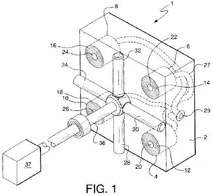
Fig.1 is an isometric representation of keys components of the present invention.
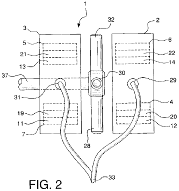
Fig.2 is a side view representation of the present invention showing the two housed sets of coil elements and their relationship with the magnets.

Fig.3 is an explanatory view, showing the generation of flux lines which forms the basis for the operation of the present invention.

Fig.4 is an alternate embodiment of the present invention.
DETAILED
DESCRIPTION OF THE INVENTION
Fig.1 and Fig.2 show a clear depiction of the components of alternating current generator 1 of the subject invention. Generator 1 comprises housings 2 and 3. For simplicity purposes and ease of understanding, only housing 2 is shown in Fig.1. It must be understood, however, that generator 1 of the present invention is configured for use with both housings 2 and 3. Housing 2 contains coil elements 4, 6, 8 and 10. Each coil element comprises multiple windings 12, 14, 16, and 18, respectively, wound around inner steel or similar metal cores 20, 22, 24, and 26, respectively. Each steel core extends the full length and directly through each of the coil elements. Coil elements 4, 6, 8, and 10 are mounted within housing 2, such that the end surfaces of the coil elements and the ends of cores 20, 22, 24, and 26 are positioned flush with the external surface of housing 2.
Housing 3 also contains four coil elements positioned identically as has been described with regard to housing 2. Two of these coil elements 5 and 7 are shown in Fig.2. Coil element 5 has multiple windings 13 and centre core 21 and coil element 7 has multiple windings 11 and centre core 21.
Magnets 28, 30, 32, and 34 are secured to shaft 36, which is configured to be rotated by conventional power source 37, such as a diesel engine, turbine, etc. Magnets 28, 30, 31, and 32 all have ends with outwardly extending polarities. Magnets 28, 30, 32, and 34 are positioned in spaced relation to the ends of exposed cores 20, 22, 24 and 26 of coil elements 4, 6, 8, and 10 and in spaced relation to the ends of the four exposed cores in the four coil elements located in housing 3, cores 19 and 21 being shown in Fig.2. All magnets are equidistantly spaced on and around shaft 36, such that the outwardly extending pole of one magnet circumferentially follows the outwardly extending pole of the next magnet. The north polar end of one magnet may follow the south polar end of the next magnet or the polar end of one magnet may follow a magnet with the same polar end.
While four magnets and four cores are shown, it is contemplated that additional magnets and cores could be employed in the generator. Also, while permanent magnets are shown in the drawings, electromagnets could also be used, as they produce the same magnetic flux.
Alternating electrical current is generated when power source 37 rotates shaft 36, thus causing rotation of magnets 28, 30, 32, and 34 in spaced, adjacent relation to the ends of cores 20, 22, 24, and 26 of coil elements 4, 6, 8, and 10, and in spaced, adjacent relation to the ends of cores 19 and 21 of coil elements 7 and 5 and the ends of the cores of the other two similarly aligned coil elements in housing 3. The current which is generated is transmitted through electrical conductive wiring 27, which merges at connection points 29 in housing 2 and 31 in housing 3, for the consolidated transmission at connection point 33 of the electricity produced.
As best represented in Fig.2, when magnet 28 is rotated in space relation to the end of core 20 of coil element 4, flux lines 100 of the magnet cut the core at the centre of the coil element. This induces an alternating electrical current that oscillates back and forth along the length of core 20. This oscillating current creates an expanding and collapsing set of magnetic flux lines 200 which expand and contract through every inch of coil windings 12. Expanding and collapsing field 200 induces an alternating electric field in coil element 4 which is accompanied by an expanding and collapsing magnetic field 300. It is noted, significantly, that none of the magnetic field lines 100, 200 and 300, act in a negative fashion or in an opposing action. This allows the subject invention to overcome the limitations of Lenz's law, which states that whenever there is a change in magnetic flux in a circuit, an induced electromotive force is set-up tending to produce a current in a direction which will oppose the flux change.
Fig.3 illustrates an alternate embodiment of the invention to that which is shown in Fig.1. As shown in Fig.3, coil element 44 with outer windings 58 and inner steel core 66, coil element 46 with windings 56 and core 64, coil element 48 with windings 54 and core 62, and coil element 50 with outer windings 52 and core 60 are positioned adjacent to rotor 67, which is mounted on shaft 69. Magnets 68 and 72 are mounted on rotor 67 such that the north poles of the magnets are positioned in spaced relation to coil elements 44, 46, 48 and 50. Magnets 70 and 74 are mounted on rotor 67 such that the south poles of the magnets are also positioned in spaced relation to coil elements 44, 46, 48, and 50. All magnets are fixedly mounted on rotor 67 such that a north pole of one magnet circumferentially follows a south pole of the next magnet in line. The contemplated gap between the magnets and coil element cones is approximately 0.0001 of an inch, although the scope and use of the invention should not be deemed restricted to this distance.
As in the prior embodiment, rotation of magnets 68, 70, 72, and 74, by rotation of shaft 69 and hence rotor 67, causes the flux lines of the magnets to cut cores 60, 62, 64, and 66 of coil elements 44, 46, 48, and 50, eventually resulting in the output of electrical current as previously described.
It is noted that the larger the diameter of rotor 67, the more coil elements can be positioned around the rotor. The greater the number of coil elements, the slower rotor 67 needs to rotate; however, there is a power loss in so doing. In addition, while rotor 67 is shown as being circular, it may be as square in shape or formed of as other appropriate multi-sided configurations.
This unique way of generating electricity allows generation of more electrical power, e.g. anywhere in the range of 4 to 137 times more power, than prior, conventional means. It also has the advantage of obtaining unity power with very little effort.
As evidence of such power gains, reference is made to the below outlined experimental outputs from coils and magnets which produced electric power the conventional way compared with the subject invention. The conventional way of generating power, for purpose of the following experimental outputs, as referenced herein, is accomplished by cutting the wires, not the cores, of the coil's windings with the magnet’s flux.
In this regard, proof is also provided that the herein described method of generating electrical power is not affected by Lenz's Law, by reference to the readings obtained by the conventional methods as the rpm and size of the coil increase. With conventional methods, the values do not change linearly, but are less because Lenz's Law restricts the outputs from increasing proportionally to the speed and size of the coil. In comparison, however, in the method of producing power of the subject invention, there is an increase in the readings of V (voltage), I (current), and P (power) which are actually larger than anticipated.
It is also noted that, just like a transformer, when the number of turns ratio is increased, V increases and I decreases, which is exactly what is seen at the various rpm readings for the different size coils. However, they do not increase or decrease proportionally.
Thus, this presents the ideal model for producing electrical power that corresponds to the general law that states that as the speed increases, the voltage will increase proportionally, through the equation:
V = q (charge) × v (velocity) × B (magnetic field strength). This also holds true for a coil, in that transformers increase proportionally to the turns ratio.
With reference to the voltage outputs for each of the coils, 1100T, 2200T and 5500T, it is seen that they are consistent with the types of voltage outputs for a transformer action. That is to say, as the turns ratio goes up in a transformer so does the voltage. Since the increases in voltage between the number of turns is not exactly 2 to 5 times, one can pick any one of the coils and assume it is accurate and adjust the other coils accordingly. Thus, by fixing the 1100T coil, the other coils become 2837T and 5896T respectively. By fixing the 2200T coil, the other coils become 853T and 4572T respectively. And by fixing the 5500T coil, the other coils become 1026T and 2646T respectively. Also, if the adjustments are made as described here, i.e. that the coils are bigger than originally thought, and they are applied to the voltages for the conventional method of generating power, the voltages do not increase proportionally but are actually smaller than they are supposed to be, additional proof that Lenz's Law has application to conventional generators, but not to this invention.
The proportional changes in the voltage relative to speed can also be seen. Thus, considering the 350 RPM speed as accurate, the 1200 RPM and 1300 RPM speeds will adjust to 906 RPM and 1379 RPM respectively. Considering the 1200 RPM speed as accurate, the 350 RPM and 1300 RPM speed becomes 464 RPM and 1826 RPM respectively. And finally, considering the 1300 RPM speed as accurate, the 350 RPM and 1200 RPM speeds become 330 RPM and 854 RPM respectively.
It is noted that in using the various RPM readings based upon the above, it is seen that, in the conventional way of generating power, there are losses associated with the measured values. The calculated values again show the application of Lenz's Law in the conventional way of generating power, but not to this invention. In fact, whether or not there is an adjustment of RPM speed or coil size, the power generation of this invention is in no way affected by Lenz's Law.
Since Lenz's Law has no effect in this generator, it can be assumed that the voltages increase proportionally to the speed of the magnets rotation. Therefore, one can extrapolate the expected voltages at 1800 RPM, the speed necessary to create 60 Hz. With regard to this generator, for each of the three coils from the 350 RPM, 1200 RPM and 1300 RPM speeds, the following results (values are based on one coil/magnet.):
The reason the current is not changing linearly as the laws of physics imply from transformers, i.e. as voltage goes up based on the number of turns, the current goes down proportionally to the voltage gain, is due to the fact that the inductive reactance is also going up. See the following chart for the inductive reactances for each coil at each speed.
Impedance (Z) or inductive reactance (X(L)) for a circuit with only a coil in it is the AC voltage divided by the AC current, and the inductance (L) is Z/2 × pi × F (frequency). For a circuit with a resistor and a coil
Z = square root of (R (resistance) squared + X(L) squared)).
The following is the chart of impedance Z for all coil sizes at all speeds for the conventional method of generating power and the method of generating power with this invention:
Where:
“T” stands for Turns,
“CM” stands for Conventional Method and
“SI” stands for Subject Invention:
(1) For 350 RPM for 1100T, 2200T and 5500T coils,
1. (a) CM: 0.57v / 56.6 mA = 10.021 ohms = Z
(b) SI: 1.14v / 106.6 mA = 10.694
ohms = Z
2. (a) CM: 0.93v / 32.4 mA = 28.704 ohms = Z
(b) SI: 2.94v / 70.1 mA = 41.94
ohms = Z
3. (a) CM: 2.09v / 17.3 mA = 120.81 ohms = Z
(b) SI: 6.11v / 37.9 mA = 161.21
ohms = Z
(2) For 1200 RPM for 1100T, 2200T and 5500T coils:
1. (a) CM: 1.45v / 60.2 mA = 23.387 ohms = Z
(b) SI: 2.95v / 141 mA = 20.922
ohms = Z
2. (a) CM: 3.225v / 36.2 mA = 89.088 ohms = Z
(b) SI: 7.53v / 73.5 mA = 102.449
ohms = Z
3. (a) CM: 4.81v / 17 mA = 282.941 ohms = Z
(b) SI: 11.23v / 31.4 mA = 357.643
ohms = Z
(3) For 1300 RPM for 1100T, 2200T and 5500T coils:
1. (a) CM: 1.6v / 83 mA = 19.27 ohms = Z
(b) SI: 4.59v / 157 mA = 29.236
ohms = Z
2. (a) CM: 2.75v / 50.4 mA = 54.455 ohms = Z
(b) SI: 7.74v / 88.5 mA = 87.458
ohms = Z
3. (a) CM: 5.061v / 17.3 mA = 292.543 ohms = Z
(b) SI: 12.76v / 36.4 mA = 350.549
ohms = Z
(4) For 400 RPM for 2300T coil with 24 gauge wire and 0.5" core:
(a) CM: 0.15v / 3.7 mA = 40.541
ohms = Z
(b) SI: 2.45v / 26.2 mA = 93.511
ohms = Z
(5) For 1200 RPM for 2300T coil with 24 gauge wire and 0.5" core:
(a) CM: 0.37v / 2.7 mA = 137.037
ohms = Z
(b) SI: 4.1v / 10.3 mA = 398.058
ohms = Z
(6) For 1400 RPM for 2300T coil with 24 gauge wire and 0.5" core:
(a) CM: 0.58v / 2.4 mA = 241.667
ohms = Z
(b) SI: 8.3v / 7.8 mA = 1065.385
ohms = Z
(7) For 400 RPM for 2300T coil with 24 gauge wire and 0.75" core:
(a) CM: 0.23v / 4.2 mA = 54.762
ohms = Z
(b) SI: 0.37v / 7.2 mA = 51.389
ohms = Z
(8) For 1200 RPM for 2300T coil with 24 gauge wire and 0.75" core:
(a) CM: 0.79v / 3.4 mA = 232.353
ohms = Z
(b) SI: 0.43v / 6.9 mA = 207.246
ohms = Z
(9) For 1400 RPM for 2300T coil with 24 gauge wire and 0.75" core:
(a) CM: 0.79v / 3.21 A = 246.875
ohms = Z
(b) SI: 2.1v / 2.7 mA = 777.778
ohms = Z
(10) For 400 RPM for 6000T coil with 28 gauge wire and 0.5" core:
(a) CM: 0.49v / 2 mA = 245
ohms = Z
(b) SI: 5.48v / 0.13 mA = 421.538
ohms = Z
(11) For 1200 RPM for 6000T coil with 28 gauge wire and 0.5" core:
(a) CM: 1.25v / 1.5 mA = 833.333
ohms = Z
(b) SI: 15.04v / 4.1 mA = 3668.293
ohms = Z
(12) For 1400 RPM for 6000T coil with 28 gauge wire and 0.5" core:
(a) CM: 2.08v / 1.1 mA = 1890.909
ohms = Z
(b) SI: 18.76v / 2.5 mA = 7504
ohms = Z
(13) For 400 RPM for 6000T coil with 28 gauge wire and 0.75" core:
(a) CM: 0.64v / 1.7 mA = 376.471
ohms = Z
(b) SI: 7.97v / 7.4 mA = 1077.027
ohms = Z
(14) For 1200 RPM for 6000T coil with 28 gauge wire and 0.75" core:
(a) CM: 2.08v / 1.3 mA = 1600
ohms = Z
(b) SI: 20.4v / 5.6 mA = 3642.857
ohms = Z
(15) For 1400 RPM for 6000T coil with 28 gauge wire and 0.75" core:
(a) CM: 2.28v / 1.2 mA = 1900
ohms = Z
(b) SI: 28.4v / 2.1 mA = 13523.81
ohms = Z
It is noted that, based upon the variations of wire size, core size and number of turns, the following effects take place:
(a) the smaller the wire size the higher the gains regardless of speed;
(b) the greater the number of turns, generally the higher the gains; and
(c) the smaller the core size the higher the gains.
However, when comparing coils with smaller cores but a higher number of turns, the effects stay about the same.
Finally, the magnets are placed in the rotor so that they are all north or south poles up or out. A pure half-wave generator is created without rectifying the AC signal, which otherwise must be accomplished in a normal AC generator with electronic components in an electronic circuit.
Experimental Values for Producing Power the Conventional Way and with the Subject Invention:
The results were achieved using a small 3" magnet with a diameter of ±2" on a 1.25" high coil of 1" diameter and 3/8" centre/core of steel. (Unknown wire gauge size.)
(a) Conventional method of generating electricity:
1. 0.324 volts
2. 2.782 mA (milli-amps)
3. 0.9014 mW (milli-watts)
(b) Subject invention method of generating electricity:
1. 7.12 volts
2. 17.35 mA
3. 100.87 mW
(c) Associated gains of Volts, Current and
1. 2,198% over conventional voltage output.
2. 624% over conventional current output.
3. 13,713% over conventional power output.
The following results show the voltage, current and power outputs for an 1100, 2200 and 5500 turn coil of 20 gauge copper wire, 6" in length, 3" in diameter with a 0.75" core of steel. The results are those taken at 350 rpm, 1200 rpm and 1300 rpm.
(A) 350 RPM for an 1100 turn coil
Volts mA mW
(a) Conventional method: 0.57 56.6 32.3
(b) Subject invention method: 1.14 106.6 121.5
(c) Associated gains 200% 188.3% 376.6%
(B) 350 RPM for a 2200 turn coil
Volts mA mW
(a) Conventional method: 0.93 32.4 30.1
(b) Subject invention method: 2.94 70.1 206.1
(c) Associated gains 316.1% 216.4% 684%
(C) 350 RPM for a 5500 turn coil
Volts mA mW
(a) Conventional method: 2.09 17.3 36.2
(b) Subject invention method: 6.11 37.9 231.6
(c) Associated gains 292.3% 219.1% 640%
(D) 1200 RPM for an 1100 turn coil
Volts mA mW
(a) Conventional method: 1.45 60.2 87.3
(b) Subject invention method: 2.95 141 416
(c) Associated gains 203.4% 234.2% 476%
(E) 1200 RPM for a 2200 turn coil
Volts mA mW
(a) Conventional method: 3.225 36.2 116.75
(b) Subject invention method: 7.53 73.5 553.5
(c) Associated gains 233.5% 203% 474%
(F) 1200 RPM on a 5500 turn coil
Volts mA mW
(a) Conventional method: 4.81 17 81.77
(b) Subject invention method: 11.23 31.4 352.6
(c) Associated gains 235.5% 184.7% 431.3%
(G) 1300 RPM on an 1100 turn coil
Volts mA mW
(a) Conventional method: 1.6 83 132.8
(b) Subject invention method: 4.59 157 704.9
(c) Associated gains 280.6% 189.2% 530.8%
(H) 1300 RPM on a 2200 turn coil
Volts mA mW
(a) Conventional method: 2.75 50.5 138.9
(b) Subject invention method: 7.74 88.5 685
(c) Associated gains 281.5% 175.2% 493.3%
(I) 1300 RPM on a 5500 turn coil
Volts mA mW
(a) Conventional method: 5.061 17.3 87.56
(b) Subject invention method: 12.76 36.4 464.5
(c) Associated gains 252% 210% 530%
The following readings are taken from a coil with 24 gauge wire, 0.5" centre/core of steel and 2300T.
(A) 400 rpm
Volts mA mW
(a) Conventional method: 0.15 3.7 0.56
(b) Subject invention method: 2.45 26.2 64.2
(c) Associated gains 1,633% 708% 11,563%
(B) 1200 rpm
Volts mA mW
(a) Conventional method: 0.37 2.7 1
(b) Subject invention method: 4.1 10.3 42.2
(c) Associated gains 1,108% 381% 4,227%
(C) 1400 rpm
Volts mA mW
(a) Conventional method: 0.58 2.4 1.39
(b) Subject invention method: 8.31 7.8 64.82
(c) Associated gains 1,433% 325% 4,657%
The following readings are taken from a coil made with 24 gauge wire, 0.75" centre/core of copper, 2300T.
(A) 400 rpm
Volts mA mW
(a) Conventional method: 0.23 4.2 0.97
(b) Subject invention method: 0.37 7.2 2.66
(c) Associated gains 137% 171% 235%
(B) 1200 rpm
Volts mA mW
(a) Conventional method: 0.79 3.4 2.69
(b) Subject invention method: 1.43 6.9 9.87
(c) Associated gains 181% 203% 367%
(C) 1400 rpm
Volts mA mW
(a) Conventional method: 0.79 3.2 2.53
(b) Subject invention method: 2.1 2.7 5.67
(c) Associated gains 266% 84% 224%
The following readings were taken from a coil made of 28 gauge wire, 0.5" centre/core of steel and 6000T.
(A) 400 rpm
Volts mA mW
(a) Conventional method: 0.49 2 0.98
(b) Subject invention method: 5.48 13 71.24
(c) Associated gains 1,118% 65% 7,269%
(B) 1200 rpm
Volts mA mW
(a) Conventional method: 1.25 1.5 1.88
(b) Subject invention method: 15.04 4.1 61.66
(c) Associated gains 1,203% 273% 3,289%
(C) 1400 rpm
Volts mA mW
(a) Conventional method: 2.08 1.1 2.29
(b) Subject invention method: 18.76 2.5 46.9
(c) Associated gains 902% 227% 2,050%
The following readings were taken from a coil made of 28 gauge wire, 0.75" steel centre/core and 6000T.
(A) 400 rpm
Volts mA mW
(a) Conventional method: 0.64 1.7 1.09
(b) Subject invention method: 7.97 7.4 58.98
(c) Associated gains 1,245% 435% 5,421%
(B) 1200 rpm
Volts mA mW
(a) Conventional method: 2.08 1.3 2.7
(b) Subject invention method: 20.4 5.6 114.24
(c) Associated gains 981% 431% 4,225%
(C) 1400 rpm
Volts mA mW
(a) Conventional method: 2.28 1.2 2.74
(b) Subject invention method: 28.4 2.1 88.04
(c) Associated gains 1,246% 175% 2,180%
The extrapolated voltages for the items immediately above at the 1800 RPM speed for the method of the subject invention are as follows:
(A) 400-1400 RPM, 0.5" core, 2300T:
(1) 11.025v
(2) 6.15v
(3) 10.68v
(B) 400-1400 RPM, 0.75" core, 2300T:
(1) 1.665v
(2) 2.145v
(3) 2.7v
(C) 400-1400 RPM, 0.5" core, 6000T:
(1) 24.66v
(2) 22.56v
(3)24.12
(D) 400-1400 RPM, 0.75" core, 6000T:
(1) 10.25v
(2) 30.6v
(3) 36.51v
Some of the readings above do not seem consistent with others. This is attributed to the possibility that the wire connections may have been faulty or the proximity of the magnet relative to the core or coil may not have been the same. This was not taken into account at the time the tests were done.
The following figures are derived based on the premise that the subject invention has characteristics of a transformer when the number of turns on the coils change. In nearly all these situations, the subject invention acts exactly like a transformer, while the conventional way of producing electricity does not.
CM = conventional method;
SI = subject invention;
|
350 RPM |
|
1100 to 2200 Turns |
1100 to 5500 Turns |
2200 to 5500 Turns |
|
CM: |
expected voltage: |
1.14 volts |
2.85 volts |
2.325 volts |
|
|
actual voltage: |
0.93 volts |
2.09 volts |
2.09 volts |
|
|
expected current: |
28.3 mA |
11.32 mA |
12.96 mA |
|
|
actual current: |
32.4 mA |
17.3 mA |
17.3 mA |
|
|
expected power: |
32.3 mW |
32.3 mW |
30.1 mW |
|
|
actual power: |
30.1 mW |
36.2 mW |
36.2 mW |
|
|
expected voltage gain: |
2 |
5 |
2.5 |
|
|
actual voltage gain: |
1.636 |
3.667 |
2.247 |
|
|
expected current gain: |
0.5 |
0.2 |
0.4 |
|
|
actual current gain: |
0.572 |
0.306 |
0.534 |
|
|
expected power gain: |
1 |
1 |
1 |
|
|
actual power gain: |
0.932 |
1.12 |
1.203 |
|
|
|
|
|
|
|
SI: |
expected voltage: |
2.28 volts |
5.70 volts |
7.35 volts |
|
|
actual voltage: |
2.94 volts |
6.11 volts |
6.11 volts |
|
|
expected current: |
53.30 mA |
42.64 mA |
28.04 mA |
|
|
actual current: |
70.10 mA |
37.90 mA |
37.90 mA |
|
|
expected power: |
121.74 mW |
243.05 mW |
206.09 mW |
|
|
actual power: |
206.10 mW |
231.60 mW |
231.60 mW |
|
|
expected voltage gain: |
2 |
5 |
2.5 |
|
|
actual voltage gain: |
2.579 |
5.36 |
2.078 |
|
|
expected current gain: |
0.5 |
0.2 |
0.4 |
|
|
actual current gain: |
0.658 |
0.356 |
0.5407 |
|
|
expected power gain: |
1 |
1 |
1 |
|
|
actual power gain: |
1.696 |
1.906 |
1.124 |
|
1200 RPM |
|
1100 to 2200 Turns |
1100 to 5500 Turns |
2200 to 5500 Turns |
|
CM: |
expected voltage: |
2.90 volts |
7.25 volts |
8.06 volts |
|
|
actual voltage: |
3.225 volts |
4.81 volts |
4.81 volts |
|
|
expected current: |
30.10 mA |
12.04 mA |
14.48 mA |
|
|
actual current: |
36.2 mA |
17.0 mA |
17.0 mA |
|
|
expected power: |
87.29 mW |
87.29 mW |
116.71 mW |
|
|
expected voltage gain: |
2 |
5 |
2.5 |
|
|
actual voltage gain: |
2.22 |
3.32 |
1.49 |
|
|
expected current gain: |
0.5 |
0.2 |
0.4 |
|
|
actual current gain: |
0.6 |
0.28 |
0.47 |
|
|
expected power gain: |
1 |
1 |
1 |
|
|
actual power gain: |
1.34 |
0.94 |
0.70 |
|
|
|
|
|
|
|
SI: |
expected voltage: |
5.9 volts |
14.75 volts |
18.83 volts |
|
|
actual voltage: |
7.53 volts |
11.23 volts |
11.23 volts |
|
|
expected current: |
70.50 mA |
28.20 mA |
29.40 mA |
|
|
actual current: |
73.50 mA |
31.40 mA |
31.40 mA |
|
|
expected power: |
415.95 mW |
415.95 mW |
553.60 mW |
|
|
actual power: |
553.50 mW |
352.60 mW |
352.60 mW |
|
|
expected voltage gain: |
2 |
5 |
2.5 |
|
|
actual voltage gain: |
2.55 |
3.81 |
1.49 |
|
|
expected current gain: |
0.5 |
0.2 |
0.4 |
|
|
actual current gain: |
0.52 |
0.22 |
0.43 |
|
|
expected power gain: |
1 |
1 |
1 |
|
|
actual power gain: |
1.33 |
0.85 |
0.64 |
|
1300 RPM |
|
1100 to 2200 Turns |
1100 to 5500 Turns |
2200 to 5500 Turns |
|
CM: |
expected voltage: |
3.20 volts |
8.00 volts |
6.88 volts |
|
|
actual voltage: |
2.75 volts |
5.06 volts |
5.06 volts |
|
|
expected current: |
41.50 mA |
16.60 mA |
20.20 mA |
|
|
actual current: |
50.50 mA |
17.3 mA |
17.3 mA |
|
|
expected power: |
132.8 mW |
132.8 mW |
138.98 mW |
|
|
actual power: |
138.9 mW |
87.56 mW |
87.56 mW |
|
|
expected voltage gain: |
2 |
5 |
2.5 |
|
|
actual voltage gain: |
1.72 |
3.16 |
1.84 |
|
|
expected current gain: |
0.5 |
0.2 |
0.4 |
|
|
actual current gain: |
0.61 |
0.21 |
0.34 |
|
|
expected power gain: |
1 |
1 |
1 |
|
|
actual power gain: |
1.05 |
0.66 |
0.63 |
|
|
|
|
|
|
|
SI: |
expected voltage: |
9.18 volts |
22.95 volts |
19.35 volts |
|
|
actual voltage: |
7.74 volts |
12.76 volts |
12.76 volts |
|
|
expected current: |
78.50 mA |
31.40 mA |
35.40 mA |
|
|
actual current: |
88.50 mA |
36.40 mA |
36.40 mA |
|
|
expected power: |
720.63 mW |
720.63 mW |
685.0 mW |
|
|
actual power: |
685.0 mW |
464.50 mW |
464.50 mW |
|
|
expected voltage gain: |
2 |
5 |
2.5 |
|
|
actual voltage gain: |
1.69 |
2.78 |
1.65 |
|
|
expected current gain: |
0.5 |
0.2 |
0.4 |
|
|
actual current gain: |
0.56 |
0.23 |
0.41 |
|
|
expected power gain: |
1 |
1 |
1 |
|
|
actual power gain: |
0.95 |
0.64 |
0.68 |
The following data represents the expected and actual voltage readings for the conventional method of producing voltage and the method of the subject invention. In virtually all circumstances, the herein invention produced more voltage than the conventional method and has gains that are higher than anticipated.
|
1100 Turns |
|
350 to 1200 RPM |
350 to 1300 RPM |
1200 to 1399 RPM |
|
CM: |
expected voltage: |
1.954 volts |
2.117 volts |
1.571 volts |
|
|
actual voltage: |
1.45 volts |
1.60 volts |
1.60 volts |
|
|
expected voltage gain: |
3.429 |
3.714 |
1.083 |
|
|
actual voltage gain: |
2.544 |
2.807 |
1.103 |
|
|
|
|
|
|
|
SI: |
expected voltage: |
3.909 volts |
4.234 volts |
3.196 volts |
|
|
actual voltage: |
2.95 volts |
4.59 volts |
4.59 volts |
|
|
expected voltage gain: |
3.429 |
3.714 |
1.083 |
|
|
actual voltage gain: |
2.579 |
4.026 |
1.556 |
|
2200 Turns |
|
350 to 1200 RPM |
350 to 1300 RPM |
1200 to 1399 RPM |
|
CM: |
expected voltage: |
3.189 volts |
3.454 volts |
3.494 volts |
|
|
actual voltage: |
3.225 volts |
5.061 volts |
5.061 volts |
|
|
expected voltage gain: |
3.429 |
3.714 |
1.083 |
|
|
actual voltage gain: |
3.468 |
2.957 |
0.853 |
|
|
|
|
|
|
|
SI: |
expected voltage: |
10.081 volts |
10.919 volts |
8.157 volts |
|
|
actual voltage: |
7.53 volts |
7.74 volts |
7.74 volts |
|
|
expected voltage gain: |
3.429 |
3.714 |
1.083 |
|
|
actual voltage gain: |
2.561 |
2.633 |
1.028 |
|
5500 Turns |
|
350 to 1200 RPM |
350 to 1300 RPM |
1200 to 1399 RPM |
|
CM: |
expected voltage: |
7.167 volts |
7.62 volts |
5.211 volts |
|
|
actual voltage: |
4.81 volts |
5.061 volts |
5.061 volts |
|
|
expected voltage gain: |
3.429 |
3.714 |
1.083 |
|
|
actual voltage gain: |
2.301 |
2.422 |
1.052 |
|
|
|
|
|
|
|
SI: |
expected voltage: |
20.951 volts |
22.693 volts |
12.166 volts |
|
|
actual voltage: |
11.23 volts |
12.76 volts |
12.76 volts |
|
|
expected voltage gain: |
3.429 |
3.714 |
1.083 |
|
|
actual voltage gain: |
1.838 |
2.088 |
1.049 |
|
2300 Turns |
(0.5” core 24 gauge wire) |
400 to 1200 RPM |
400 to 1400 RPM |
1200 to 1400 RPM |
|
CM: |
expected voltage: |
0.45 volts |
0.525 volts |
0.432 volts |
|
|
actual voltage: |
0.37 volts |
0.58 volts |
0.58 volts |
|
|
expected voltage gain: |
3.00 |
3.50 |
1.167 |
|
|
actual voltage gain: |
2.467 |
3.867 |
1.568 |
|
|
|
|
|
|
|
SI: |
expected voltage: |
7.35 volts |
8.57 volts |
4.785 volts |
|
|
actual voltage: |
4.10 volts |
8.31 volts |
8.31 volts |
|
|
expected voltage gain: |
3.00 |
3.50 |
1.167 |
|
|
actual voltage gain: |
1.673 |
3.392 |
2.027 |
|
2300 Turns |
(0.75” core 24 gauge wire) |
400 to 1200 RPM |
400 to 1400 RPM |
1200 to 1400 RPM |
|
CM: |
expected voltage: |
0.69 volts |
0.805 volts |
0.922 volts |
|
|
actual voltage: |
0.79 volts |
0.79 volts |
0.79 volts |
|
|
expected voltage gain: |
3.00 |
3.50 |
1.167 |
|
|
actual voltage gain: |
3.435 |
3.435 |
1.00 |
|
|
|
|
|
|
|
SI: |
expected voltage: |
1.11 volts |
1.295 volts |
1.688 volts |
|
|
actual voltage: |
1.43 volts |
2.10 volts |
2.10 volts |
|
|
expected voltage gain: |
3.00 |
3.50 |
1.167 |
|
|
actual voltage gain: |
3.865 |
5.676 |
1.469 |
|
6000 Turns |
(0.5” core 28 gauge wire) |
400 to 1200 RPM |
400 to 1400 RPM |
1200 to 1400 RPM |
|
CM: |
expected voltage: |
1.47 volts |
1.715 volts |
1.459 volts |
|
|
actual voltage: |
1.25 volts |
2.08 volts |
2.08 volts |
|
|
expected voltage gain: |
3.00 |
3.50 |
1.167 |
|
|
actual voltage gain: |
2.551 |
4.245 |
1.664 |
|
|
|
|
|
|
|
SI: |
expected voltage: |
16.44 volts |
19.18 volts |
17.668 volts |
|
|
actual voltage: |
15.04 volts |
18.76 volts |
18.76 volts |
|
|
expected voltage gain: |
3.00 |
3.50 |
1.167 |
|
|
actual voltage gain: |
2,745 |
3.423 |
11.247 |
|
6000 Turns |
(0.75” core 28 gauge wire) |
400 to 1200 RPM |
400 to 1400 RPM |
1200 to 1400 RPM |
|
CM: |
expected voltage: |
1.92 volts |
2.24 volts |
2.427 volts |
|
|
actual voltage: |
2.08 volts |
2.28 volts |
2.28 volts |
|
|
expected voltage gain: |
3.00 |
3.50 |
1.167 |
|
|
actual voltage gain: |
3.25 |
3.563 |
2.427 |
|
|
|
|
|
|
|
SI: |
expected voltage: |
23.91 volts |
27.895 volts |
23.80 volts |
|
|
actual voltage: |
20.40 volts |
28.40 volts |
28.40 volts |
|
|
expected voltage gain: |
3.00 |
3.50 |
1.167 |
|
|
actual voltage gain: |
2.56 |
3.563 |
1.392 |
CLAIMS
1. A generator for providing alternating electrical current comprising:
(a) an independently supported rotating drive shaft;
(b) a plurality of spaced apart magnets extending outwardly from the shaft, the magnets each creating magnetic flux and having a polar end with a particular north or south polarity, said magnets being circumferentially spaced and mounted around the shaft, such that the polar ends of the magnets extend away from and circumferentially around the shaft;
(c) a plurality of stationary coil elements, each said coil element comprising electrical windings wound about substantially the entire coil element, each of said coil elements further comprising a solid metal core with two ends extending substantially through the coil element at the centre of the coil element, each element being positioned such that one end of each of the cores is located in spaced, adjacent relation to the magnets, whereby rotation of the shaft causes rotation of the magnets around the shaft and in spaced, adjacent relation to the cores of the coil elements, the magnetic flux of the magnetics cutting the cores of the coil elements, creating alternating current in the coil elements; and
(d) a first housing in which some of the plurality of coil elements are mounted and a second housing in which the remainder of the plurality of coil elements are mounted.
2. The generator as in claim 1 wherein the magnets are spaced 90° apart around the shaft.
3. The generator as in claim 1 wherein magnets with north polar ends alternate with the magnets with south polar ends in spaced, circumferential relation around the shaft.
4. The generator as in claim 1 wherein all the plurality of magnets are magnets with the same polar ends.
5. The generator as in claim 1 wherein the magnets are equidistantly spaced around the shaft.
6. The generator as in claim 1 wherein the plurality of magnets is rotated by the drive shaft between and in spaced apart relation with the housings.
7. The generator as in claim 1 further comprising four magnets extending from the shaft, adjacent magnets being positioned perpendicular to each other, each magnet having either an outwardly extending north or south polar end, and said magnets being positioned such that a north polar end magnet follows a south polar end magnet, in spaced, circumferential relation around the shaft.
8. The generator as in claim 1 further comprising multiple north polar end magnets and multiple south polar end magnets extending from the shaft, said magnets being positioned in spaced, circumferentially relation around the shaft.
9. The generator as in claim 1 in which the shaft is positioned within a rotor and the magnets are circumferentially mounted on the rotor.
10. The generator as in claim 1 in which the shaft is connected to power means for rotating the shaft, whereby upon rotation of the shaft, the magnets are rotated around the shaft in spaced relation to the cores of the coil elements, thereby inducing an alternating electrical field along the length of each of the cores, thereby producing an alternating electric current in the windings of the coil elements.
11. The generator as in claim 10 further comprising means to transmit the alternating electrical current for electrical power usage.
GEOFFREY SPENCE: ENERGY CONVERSION SYSTEM
US Patent 4,772,816
20th September 1988
Inventor: Geoffrey M. Spence
ENERGY CONVERSION SYSTEM
This is a slightly reworded excerpt from this patent which has a substantial electrical output capable of providing it’s own electrical input to be self-powering as well as generating kilowatts of excess power. The highly-respected Dr. Harold Aspden comments:
“In my Energy
Science Report No. 8I, I also mentioned the apparatus designed by Geoffrey
Spence, an inventor based in
The questions then are whether the Spence invention really works and whether it is commercially viable? Well, I wrote that Energy Science Report back in 1996, six years ago, and it is only a few months ago that I heard any more of that project. Geoffrey Spence has developed the prototype product to the stage where he has closed the loop in the sense that a portion of the output power was fed back to impart the energy needed to sustain the electron beams. He has a self-sustaining unit that can deliver kilowatts of useful electrical power with no visible energy input.”
ABSTRACT
The apparatus uses a magnetic field (80) to accelerate a charged particle radially towards a target electrode (10). The increased kinetic energy of the particles enables the particle to give up more electrical energy to the target electrode (10) than was initially given to it. This charges the target electrode (10), and the increased energy is extracted from the apparatus by connecting an electrical load between the target electrode and a point of lower or higher potential.
1717413 Jun, 1929 Rudenberg 310/306.
3202844 Aug, 1965 Hatch 310/306.
3234411 Feb, 1966 Klein 310/306.
3312840 Apr, 1967 Gabor 310/306.
3393330 Jul, 1968 Vary 310/306.
3899696 Aug, 1975 Shimadu 310/306.
DESCRIPTION
This invention relates to a process and apparatus for generating a potential difference between two or more electrodes and using charged particles as energy carriers.
Electrical power is usually generated by burning a fossil fuel and converting the energy released into rotary motion which drives electrical generators. This is cost-effective only if carried out on a large scale, the conversion process being inefficient; utilising natural resources, and producing waste products which can cause serious environmental pollution. An additional disadvantage is that the electrical power cannot be supplied directly to road vehicles or ships.
The energy-conversion process of this invention involves no health or pollution hazard and generates electrical power directly by a single-stage process without waste products. The overall energy-conversion factor and power-to-weight ratio are both high, making the apparatus suitable for most fixed and mobile applications.
One known apparatus for doing useful work by operating on electrons with a magnetic field is called the "betatron". This includes a doughnut-shaped vacuum chamber between the poles of a specially-shaped electromagnet. Thermionically-produced electrons are injected into the chamber with an initial electrostatic energy of about 50 keV. As the magnetic field builds up during its positive-going half-cycle, it induces an electromotive force within the doughnut, which force accelerates the electrons and forces them to move in an curved path, by interaction with the magnetic field. An important distinction between the betatron and the energy converter of this invention is that in the former the magnetic field has got to be able to increase over a very short period, in order to accelerate the electrons sufficiently, whereas in the latter the magnetic field is virtually constant and the electrons fall inwardly to give up both their kinetic energy and electric charge to a central electrode.
The present invention aims at providing an energy converter which may be mobile and which has a permanent magnet or an energised source of magnetic radiation associated with it in order to amplify the electrical energy initially imparted to charge particles fed to, or produced in, a so-called "vacuum" chamber forming part of the generator, which increased energy is extracted from the target electrode on which the particles are incident.
Accordingly the present invention provides an energy converter as per the appended claims.
While the invention is not to be limited to any particular theory of operation, it is based on the fact that, when a charged particle is constrained to move through a radial distance d (irrespective of the path which it actually follows) through a magnetic field of intensity H, the work done on the particle is H x d. For an electron carrying a charge e, and moving at a speed v over distance d, the total force on the electron is the centripetal force the sum of H x e x v, less the force exerted on the electron in the opposite direction by the centrifugal force, which is the sum of (m x v2)/r. By making the radius of the centre electrode appreciably greater than the orbit of equilibrium, the centrifugal force can be minimised, thus maximising the centripetal force, and hence the work done in bringing the charge to the electrode.
The process by which the converter of this invention works uses, as a source of charge, electrically-charged particles, for example electrons and/or ions. Two or more electrodes are housed in a low-pressure chamber. A magnetic field as specified below traverses the chamber: it emanates from a permanent magnet, electromagnet or a source of magnetic radiation. An external source of energy is used to give the charge particles initial kinetic energy, for example by heating, acceleration through an electric field, or from nuclear radiation. The energy-conversion process uses the magnetic field to transfer the charged particles along a desired orbit until they impinge on a central electrode (cathode). The work done on the particles (therefore the electrical potential attained by the cathode) is proportional to the resultant magnetic force times the distance over which the force acts. As the particles move within the chamber they cross the magnetic field. This produces a force acting on the particles, the force being proportional to the field strength, speed and electrical charge of the particles, and the sine of the angle of incidence between the path of the particle and the magnetic lines of force. This force has an angular component and a centripetal one, which forces the particles to travel along a spiral orbit.
An opposing centrifugal force also acts on the particles in opposition to the centripetal magnetic force. The electrode potential is proportional to the work required to be done on the charged particles to overcome both the centrifugal force and the electric field around the cathode as the charges accumulate and the potential difference between the electrodes increases. Maximum electrode potential is reached when the centrifugal and repulsive forces are equal to the centripetal force, after which no further charged particles reach the electrode. The radius of the electrode determines the minimal value voltage between the central and an outer electrode: as the central electrode radius is reduced (by sputtering or erosion) the centrifugal force increases, reducing the number of charged particles which can reach the central electrode and therefore the electrode potential, for a given field strength and particle speed. The difference in mass between ions and lighter charged particles, such as electrons, results in different centrifugal forces for given particle kinetic energies. The generator output and efficiency are optimised when the generator uses the maximum magnetic field to minimise the centrifugal force and to maximise the radial distance over which the force acts for a given field strength. Particles having the highest charge-to-mass ratio should be used.
Low pressure gases can be used as a charge source when ionised by particle collision and excitation within the chamber. Doped gases can minimise the energy level for ionising gas atoms/molecules thereby improving efficiency. However, the resultant magnetic force is lower for the heavier ions due to their lower velocity so that the electric field radiated by the high voltage electrode (cathode) can attract oppositely charged particles (+ ions) and subsequently discharge the electrode reducing the output voltage. Various methods can be used to overcome or reduce this effect. For example one method would be to separate the opposite charges and/or to use electrical biased grids to control the flow of opposite charges to the high voltage electrode.
Gaseous systems are generally more complex than single charge systems, providing higher currents at lower voltages, whereas single charge systems, for example electrons used in high vacuum chambers, can generate higher voltages.
The magnetic field can be from one or more permanent magnets and/or from one or more electromagnets; a static magnetic field produces a constant output voltage, while a varying field produces a varying voltage for particles with equal mass and velocity.
An external source is used to accelerate the charged particles to give them initial kinetic energy, which is released as heat when the particles collide with the electrode. When the energy represented by the increased voltage between the electrodes is greater than the energy required to provide the charged particles; and accelerate them, the conversion process is self-sustaining, the output energy being the difference between the sum of the kinetic energy lost and the energy generated. Charge flows from the central electrode via an external load to another electrode. The electrical energy (work) released is a function of the current (sum of charges that flow per second) times the potential difference. Electrical and thermal output can be controlled by varying: the field strength; the particle speed; the particle density (mean free path), and/or by incorporating a grid to control the rate at which particles reach the central electrode. The output is also proportional to the heat lost or gained, since the translational energy of the particle is proportional to its temperature. Heat liberated at the electrode can be returned to the particles to maintain their energy, or be utilised in a heat exchanger for external use. The generator normally uses non-reacting conductive material to prevent chemical reaction by gases, coolants etc. with the electrodes, container walls or other components. Various particle trajectories, directional movements and positioning of the orbiting particles can be used with appropriate magnetic fields. The low-pressure gas can be ionised by any suitable means: one method would be to use an electron/ion gun where the plane and direction of the injected particles is correct for the applied magnetic field. In gas apparatus, the electrons flowing through the external circuit, on reaching the anode, recombine with a gaseous ion to form a neutral gas atom/molecule. This atomic particle is duly re-ionised by collision and/or the electric fields, the energy being directly or indirectly derived from the work done by the resultant force acting on the charged particles.
In order that the invention may be better understood, it will now be described with reference to the accompanying schematic drawings, which are given by way of example, and in which:
Fig.1 shows schematically a cross-section of the generator; and the path followed by a particle during the energy-conversion process;
Fig.2 shows an axial cross-section of one type of apparatus for the invention, using permanent magnets; and a grid controlling ion migration to the cathode.
Fig.3 shows a cross-section of the apparatus of Fig.2 along the line A--A;
Fig.4 is a diagrammatic section through one form of converter using electrons, showing a circular series of electron sources;
Fig.5 is an axial cross-section through a more practical embodiment of the Fig.4 converter;
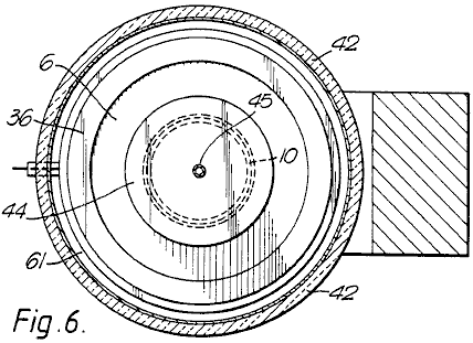
Fig.6 is a section along the line VI--VI of Fig.5;
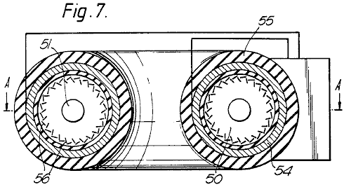
Fig.7 is a cross-section along a diameter of a doughnut-shaped (toroidal) high-power converter;
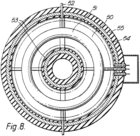
Fig.8 is a section on line A--A of Fig.7, and
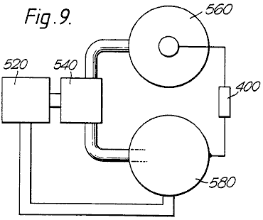
Fig.9 is a scheme of a two-stage converter, using both forms of charged particles concurrently.
As shown in Fig.1, a charged particle is injected along a trajectory 2 into a magnetic field extending normal to the plane of the drawing. The field permeates the space 4 of the annular cross-section within a cylindrical chamber 6. The magnetic field produces a force on the particle, extending at right angles to both it’s direction of motion and the magnetic field. The resultant centripetal force causes the particle to follow a spiral path 8 ending on the central electrode 10 spaced radially inwards from the outer cylindrical electrode 12. The extra energy acquired by the particle is a function of the radial distance travelled and the strength of the magnetic field between the electrodes. This energy is given up on impact with the central electrode, in the form of heat and/or work done in bringing the charge against the opposing electric field to the electrode. In the absence of the central electrode 10, the electrons would follow the orbit of equilibrium 3, this being the orbit followed by a particle when the centrifugal and centripetal forces balance, resulting in no work being done on the particle.
As shown more particularly in Fig.2 and Fig.3, the energy converter 1 consists basically of a annular chamber 6 having an outer cylindrical electrode 12; an inner cylindrical electrode 10, and two gas-tight walls 14 of electrical insulation material. In the electrode 12 is a port 22 through which an electron gun 20 can inject electrons into space 4. Additionally or alternatively, an ion gun 18 can inject positively-charged particles through port 16.
Seated on the major flat surfaces of chamber 6 are magnetic pole-pieces 24 giving rise to a uniform magnetic field 80 which traverses the space 4 parallel with the axis of chamber 6. The magnets may be ceramic permanent magnets, or they may be electromagnets. In either case, means (not shown) may be provided for adjusting the magnetic field strength.
Heavy conductors 26 connect the two electrodes to terminals 28 across which a resistive load can be placed to dissipate the generator output.
A vacuum pump (not shown) has its inlet in communication with the interior of chamber 6 so that the gas pressure in the generator can be reduced to, and kept at, a desired sub-atmospheric value. Associated with the pump, or separate from it, may be means for ensuring that the gas in the generator is of a desired composition, for instance, one which enhances the possibility of ionising collisions between the charged particles and gas atoms or molecules. One such suitable gas would be neon containing 0.1% argon by volume.
In order to cause the generator to start working, it is necessary to start the vacuum pump and to energise the electron gun or each particle source. The latter involves heating a filament from an external source of power until the required internal energy level (temperature) is reached which in turn causes a piece of thermo-emissive material to emit electrons. If the electrons are to be the charge carriers, they are accelerated by a suitable electric field and projected into the space 4. Here they are further accelerated by the radial electric field between the electrodes, and at the same time have a deflecting force applied to them by the axial magnetic field through which they pass.
For an ion source, the electrons are accelerated until they impact some atoms or molecules, to produce a stream of ions which likewise pass into the space 4. With the polarities shown, the electrons are attracted to the central electrode, while the ions are pulled towards the outer electrode, which accounts for the different orientations of sources 18 and 20.
Any gas molecules which pass close to, or between, the electrodes are ionised by collision and/or the electrostatic field. Output current can then be taken through a load impedance connected across terminals 28. The impedance is matched to prevent the internal process energy dropping below a value which would prevent the re-ionisation of the gaseous atoms. As each ion is deionised at the anode, the gas atoms will tend to continue to circulate until re-ionised, the resultant force drawing both the ions (shown by solid circles) and electrons (shown by hollow circles) back into their respective orbits.
It is envisaged that, in the case of a converter using electrons, the chamber could be evacuated to a chosen sub-atmospheric pressure and sealed.
In that form of the invention shown in Fig.4, each electron source forming one of a circular series 29 of sources has a body 30 of electro-emissive material, such as molybdenum coated by caesium, heated by an electric filament 32 connected in series or parallel across a source of electric power (not shown). Immediately in front of each emitter 30 is a grid 34 of fine wires, all the grids being connected with a source of adjustable voltage so as to control the flow of electrons from the emitter. These electrons are projected through one or more acceleration electrodes 36 across which a potential difference is established along the electron path, so that each incremental electron source injects a stream of electrons having known kinetic energy into a space 38, indicated by the circle shown in a broken line, traversed by the deflection magnetic field, within which is the central, target, electrode 40. The stream of electrons injected into the magnetic field may be focused by electric and/or magnetic fields.
In the remaining Figs, those parts already referred to will retain the same references.
In the "flat disc" configuration shown in Fig.5, the annular chamber 6 is enclosed in a body 42 of thermal insulation material. The central electrode 10 is seated on insulators 44 which are pierced by conduits 45 for the passage of a coolant fluid and by an output lead 26, which may extend along the conduit so that it too is cooled.
Fig.5 shows how the deflection magnet is generally U-shaped, and has two annular pole-pieces 48, so that the magnetic field is uniform between the surface of electrode 10 and the region 38 radially innermost of the circular electron source, the electric field between the electrode 36 and emission surface 61 providing the electrons initial accelerations (kinetic energy). Fig.5 also shows how a voltage is tapped off the resistive load 40 (which thus functions as a potentiometer) and is fed through to the acceleration electrode 36.
Chamber 6 is also provided with two annular magnets 49 (or a circular series of incremental magnets) designed to influence the direction along which the electrons pass into space 38. The magnets provide local magnetic fields to ensure that the electrons meet the boundary of space 38 tangentially, i.e. with zero radial velocity.
In that form of the invention shown in Fig.7 and Fig.8, the individual "flat disc" converters of Fig.5 and Fig.6 are arranged in a type of "circular" construction, such that the magnetic fields extend along the axis of the resulting toroidal space 50 penetrated by a single toroidal target electrode 51 through which a coolant fluid may pass, along conduits 52. The cross-section of Fig.8 shows that the magnetic fields are supplemented by an electric field produced by windings 53 wound on a magnetic core 54 bounded by insulation 55.
Apart from the fact that the electrodes are common to all converters, each functions individually as described above. Obviously the power source driving the heaters for the electron guns 56; the electromagnets (if any); the acceleration electrodes and the control grids, have to be of sufficient capacity to supply the greater power needed to drive this "toroidal" configuration. Some changes would need to be made to the physical dimensioning and positioning of the relatively-complex construction, but as all these are readily understood by a competent engineer, they are not further described in this specification.
As already mentioned, the converters of this invention are of two types, i.e. electronic and ionic. Fig.9 shows diagrammatically how they may be combined to take advantage of their differences. In the two-stage power generation apparatus shown in Fig.9 the first stage consists of an ioniser 520 supplying a mixture of charged particles, i.e. ions and electrons, to a separator 540, which supplies electrons to a second stage consisting of a sealed electronic converter 560 in parallel with a gaseous ionic converter 580.
The separator 540 may use the different particle masses to separate them centrifugally using, for example, the energy conversion system of Fig.1 (without the target electrode), or it may use electromagnetic deflection fields, or a physical diffusion process, either alone or in combination. As this is not part of the subject-matter of this invention, it will not be described herein in any further detail.
In the generators of Fig.6 and Fig.8, the respective particles are deflected magnetically and accelerated radially, to function as already described above.
Because each generator is designed to operate most effectively with its particular form of charge carrier, it can be designed optimally, thus reducing the energy absorption caused by ions and electrons recombining before each has fallen on its respective target electrode. Because the electronic converter would finish up with a negatively-charged electrode, whereas the converse is true for the ionic converter, the load 400 extracting energy from the apparatus is connected across the two target electrodes. The other two electrodes of the converters may be held at the same potential, as by being connected together, or their potentials may float.
The generator can be designed to produce a wide range of output voltages and currents. The lower-energy generators are light enough to be mobile, so that they can power vehicles or act as stand-by generators. Various electrode and magnet configurations can be used, and the generators can be connected in series or parallel. Cooling jackets are fitted to prevent overheating in high-powered apparatus, and the generator is enclosed within a thermally-insulating jacket to reduce heat losses thereby increasing particle velocities. For high-energy generators, it may be necessary to provide for forced cooling of the inner electrode, as by fins projecting therefrom into a high-speed stream of suitable coolant.
Although the process according to this invention is particularly suited to using external electrical energy, it must be understood that other sources can be used to provide the initial energy input, e.g. solar and waste process heat are some of the varied energy sources which could be utilised. Control of the charge-generation process can be achieved by other means, including one or more electrically-biased grids, as used in thermionic valves.
ROBERT ALEXANDER: INCREASING ELECTRICAL POWER
US Patent 3,913,004
14th October 1975
Inventor: Robert W. Alexander
METHOD AND APPARATUS FOR INCREASING ELECTRICAL POWER
This patent shows a method of altering a standard electrical generator intended to be driven by a separate motor, so that it operates without the motor. In an example quoted, a DC input of 48 volts at 25 amps of current (1.2 kW) produces a 110 volt 60Hz AC output of 3.52 kW. That is a Coefficient Of Performance of 2.93 at an output level suited to Off-The-Grid operation of a house.
ABSTRACT
A form of rotating machine arranged in such a way as to convert a substantially constant input voltage into a substantially constant output voltage; involving generally, a rotor that revolves at a substantially constant speed within a stator, and which comprises a transformer core subjected to and having a primary motor-transformer winding and a secondary transformer-generator winding; whereby transformed and generated power are synchronously combined as increased output power.
BACKGROUND
Electrical power is frequently changed in voltage, phase, frequency, and the current is changed from alternating to direct or from direct to alternating. Voltage conversion in AC circuits is usually by means of transformers, and in DC circuits is usually by means of motor-generators. Phase conversion is also accomplished by either transformers or motor-generators, and frequency conversion is most simply done by motor-generators.
Motor-generators have various classifications of use, as follows:
(1) DC to DC, used to charge batteries and to boost voltage.
(2) AC to AC, used for frequency and phase conversion
(3) AC to DC used for all types of service, such as battery charging, generator and motor field excitation, railways, electrolysis, and speed control etc. and
(4) DC to AC used to limited extent for special applications.
To these ends combination motor-generators have been built, such as dynamotors stepping up DC voltage for radio equipment and amplidynes for reproducing a weak signal at a higher power level. When a particular variable frequency A.C. is required of a motor-generator set and the power supply is DC, the equipment will include a DC motor for variable speed and a separate alternator driven by it. Such equipment is special in nature and characterised by separation of the motor and generator and by polyphase (usually three-phase) generator windings and with auto transformers having suitable taps for obtaining the required voltages; and a DC speed controller for the motor. The phase output of such equipment is selective and its single phase capacity necessarily restricted (66%) as compared with its three-phase capacity, in which case transmission efficiency for single phase is poor.
When a higher level power output is desired, the amplidyne is employed with field windings and brushes equipped for the purpose, and in some instances to give a constant current output from a constant voltage input, for example, in inverted rotary converter provided to convert DC to A.C. However, the present invention is concerned with method and apparatus for increasing electrical power and provides a dynamo-electric converter that operates from an electrical energy supply to produce A.C. most efficiently for a useful load.
The method involves simultaneous motor-transformer-generator steps and the preferred embodiment of the apparatus involves a dynamo-electric converter (DEC) in the form of a rotary machine combined in a single rotor revolving within a stator, the rotor being comprised of a transformer core having both a primary motor-transformer winding and a secondary transformer-generator winding, and the stator being comprised of magnetic field poles.
Synchronous converters have been combined in single rotor machines to produce DC from A.C., but that effect is quite different from the effect of the present invention when A.C. is to be produced from DC in a single rotor having primary and secondary armature windings as distinguished from armature windings common to both A.C. and DC circuits. With the present invention, both a transforming and a generating effect are produced in the rotor, all of which is inherently synchronised and delivered through the A.C. outlet leads. A.C. motors and DC generators have been combined in one machine, that is in one rotor, and referred to as synchronous converters. However, synchronous converters are lacking in their ability to change DC into A.C. when operating from the former as a prime mover to drive a generator simultaneously, and more specifically to drive an alternator synchronously.
SUMMARY OF
INVENTION
This method involves the placement of a primary winding in a field to both motor the same and to have a transformer effect with respect to a secondary winding also in a field to have a generator effect. In its preferred embodiment, this dynamo-electric converter is comprised of primary and secondary windings combined in a rotor commutated to alternate a DC energy supply in and thereby motivate the rotor within a stator field. The primary winding is advantageously of fewer turns than the secondary and by means of electromotive force drives the secondary windings of more turns to cut the magnetic lines of force for the generation of electrical energy at a higher voltage level than the DC supply. This DC operated motor is shunt wound with the stator field poles fully energised by the DC energy supply, or is provided with permanent magnet field poles, to efficiently motivate the rotor and efficiently generate electrical energy in the secondary windings. The A.C. output of the secondary windings is inherently synchronised with the transformer function of the primary windings combined in the common slots of the single rotor; and by adding the transformer and generator voltages and amperages the wattage is correspondingly increased at the output.
DRAWINGS
The various objects and features of this invention will be fully understood from the following detailed description of the typical preferred form and application, which is made in the accompanying drawings, in which:
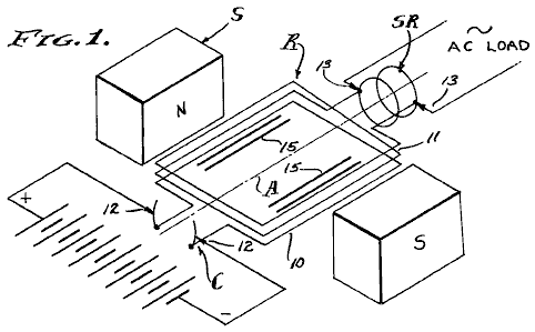
Fig.1 is a diagrammatic schematic view of the dynamo-electric converter components comprising the present invention.
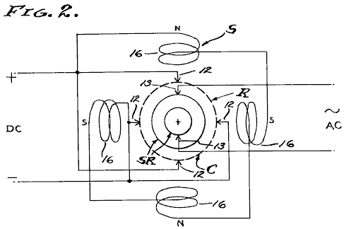
Fig.2 is a diagram of a typical commutator brush, slip ring brush and field pole arrangement which is utilised.
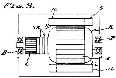
Fig.3 is a longitudinal section through a machine embodying the stator and rotor on bearings with the frame and brushes removed.
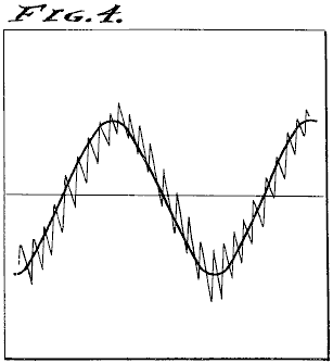
Fig.4 is a typical duplicate of an oscilloscope diagram showing the power output of the dynamo-electric converter.
PREFERRED EMBODIMENT
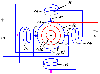
The dynamo-electric converter is illustrated diagrammatically in the drawings and involves, generally, a rotor R carried upon spaced bearings B so as to rotate on an axis A concentric within a stator S. The rotor R comprises the armature, while the stator S comprises the field, there being a commutator C associated with primary windings 10 on the rotor and slip rings SR associated with secondary windings 11 on the rotor. Brushes 12 and 13 are engaged slideably with the commutator and slip rings respectively, by conventional means, to conduct DC through the commutator C and to conduct AC through the slip rings SR. The brushes 12 and interconnected primary windings 10 comprise a motor while the brushes 13 and interconnected secondary windings 11 comprise a generator or alternator.
In practice, the field windings 16 can be separately energised or connected in parallel with the brushes 12 or shunted with respect to the primary motor winding 10. Motorisation of the armature rotor R, or motoring thereof, causes continued polarity reversals on a cycle basis as determined by the speed of rotation, and this of course results in magnetic reversals in the rotor core 15 and a consequent induction in the secondary windings 11. A feature of this invention is the combining and co-operative relationship of the primary and secondary windings which occupy common slots in and embrace a common portion of the core 15 of the rotor R, thereby to have a transformer function as well as a generator function as the lines of magnetic force are cut by the secondary windings. The stator S has field poles of opposite magnetic polarity, excited independently from the armature, or as permanent magnets, and preferably shunted across the DC input. As shown, there are four equally spaced field poles in a circumferentially disposed series.
In practice, the primary DC motor windings are of fewer turns in the rotor slots than the secondary AC generator windings. For example, the primary motor windings 10 are flat wound between north to south poles of the field while the secondary generator windings are flat wound in the same or common slots of the rotor armature. In a typical unit having a four brush commutator with 20 bars and having a 20-slot armature, the primary windings 10 are comprised of a number of turns of conductor efficiently to draw 48 volts DC at 25 amperes or 1,200 watts to rotate at 1,750 rpm, while the secondary windings 11 are comprised of a number of turns of conductor efficiently to deliver 60 cycle (by transforming and generating) 110 volts AC at 32 amperes or 3,520 watts, the volt meter used to read these values upon an actual reduction to practice being calibrated to read the root-mean-square (RMS) value of the pure sine wave, which is 70.7% of the peak voltage.
The reduction to practice previously referred to as a "typical unit" was constructed of a machine originally designed as a self-exciting 60 cps 110 volt 2.5 kVA generator to be shaft driven by a separate prime mover. Firstly, the prime mover was eliminated. The exciter windings were intended to excite the field at 45 volts DC delivered through the commutator, while the generator windings were intended to independently deliver 110-120 volts AC through the slip rings. The winding ratio between the exciter and generator windings was approximately one to three, and these are the values which determined the values employed in the present reduction to practice. However, it is to be understood that other values can be employed by design, for operation at the desired input and output voltages and amperages. It is also to be understood that the example reduction to practice disclosed herein is not necessarily the optimum design, in that other input-output power balances are contemplated, such as a DC battery input voltage substantially equal to the AC power voltage. In any case, an unexpected increase in power is realised by practising this invention.
This dynamo electric converter inherently operates at a substantially constant angular velocity with the result that the alternating cycles of the output are substantially constant. Also, the DC input voltage can be maintained at a substantially constant level with the result that the AC output voltage is also substantially constant. As shown, the output is single phase AC in which case the effective power in watts delivered is the product of current, voltage and power factor. Since the voltage is substantially constant, the current varies with load applied to the output as it is affected by the power factor. It will be seen therefore, that the apparent power represented by voltage times amperage is drawn directly from the DC input and applied to the primary motor winding 10 to motivate the rotor R for the functions previously described. It will also be seen therefore, that the DC input is commutated into AC and transformed by induction from windings 10 into windings 11.
It will also be seen therefore, that the AC generated by motorisation of the motor is synchronously imposed upon the windings 11, and all to the end that the two alternating currents are complementary and one added to the other. It will be observed that the output wattage is approximately triple the input wattage, by virtue of the synchronous superimposing of transformed input voltage and generated voltage while utilising the former to operate the rotor in order to generate the latter. A feature of this invention is the separation of the primary and secondary circuits and the consequent isolation of the inverted input DC from the outlet AC and the utilisation of input energy commensurate with output load according to amperage required for the operations to which this DEC machine is applied.
In carrying out this invention, the dynamo electric machine is conventional in design and the primary and secondary windings 10-11 are wound into the common slots of the armature as they are in self exciting generators. However, the primary windings 10 are motor-transformer windings and function totally as such. Similarly, the secondary windings 11 are wound into the armature slots together with the primary windings 10 and are powered with current that is alternated by virtue of the commutation and rotation of the armature, and consequently there is a transformer action between the primary windings 10 and secondary windings 11, and this transformer function is supplemented by generation of a superimposed current by virtue of the secondary windings 11 cutting the magnetic lines of force provided by the surrounding stator field. Consequently, there is a multiplying of power synchronously applied through the slip rings SR to the output brushes 13, and this increased output power is measurable as previously described and double or almost triple that of the input power.
METHOD
Referring now to this method of increasing electrical power, input alternating current is applied to a primary winding to both motor and alternately magnetise a core. The said primary winding is immersed in a field and consequently is caused to motor and simultaneously to perform the first stage of transforming. A second stage of transforming is then performed by a secondary winding associated with the core to function as both a transformer and a generator winding, and the output current is drawn from it at an increased power value as compared with the input power, since the current induced by transformer action is superimposed upon the current generated in cutting the magnetic lines of force by motoring the secondary winding through the magnetic field. The direct application of AC power to the primary winding is contemplated, however the present and preferred embodiment employs commutation of DC power which is thereby inverted to AC power in the process of motoring the windings and the core in which they are carried together with the secondary winding. The net result is three fold, in that there is a motoring function, a transforming function, and a generating function, all of which are inherently synchronised to increase the output power with respect to the input power.
From the foregoing it will be seen that this method, and the dynamo-electric converter termed a DEC, synchronously superimposes transformed electrical energy and mechanically generated electrical energy when inverting DC to AC as is shown by observing the oscilloscope diagram duplicated in Fig.4 of the drawings. The DC motor section of the rotor-stator unit will operate at its designed speed well within a small tolerance, by applying known engineering principles, and consequently, the AC generator-alternator section will operate at a substantially uniform frequency of, for example, 60 cycles per second. Thus, the output voltage potential is kept to a maximum while current is drawn as required, within the design capacity of the unit.
Having described only a typical preferred form and application of my invention, I do not wish to be limited or restricted to the specific details herein set forth, but wish to reserve to myself any modifications or variations that may appear to those skilled in the art:
SHIGEAKI HAYASAKA:
INDUCTION GENERATOR
Patent US 5,892,311 6th April 1996 Inventor: Shigeaki Hayasaka
INDUCTION GENERATOR HAVING A PAIR OF
MAGNETIC POLES OF THE SAME POLARITY
OPPOSED TO EACH OTHER WITH RESPECT TO A ROTATION SHAFT
This patent covers a device which is claimed to have a greater output power than the input power required to run it.
ABSTRACT
An induction generator having a pair of magnetic poles of the same polarity opposed to each other with respect to a rotation shaft is characterised by a high energy conversion efficiency. The induction generation has a rotation shaft driven by an external means; an even number of (more than three) stator cores provided to encircle the rotation shaft, predetermined gaps being provided between the adjacent stator cores; a first monopole rotor provided in the rotation shaft, surrounded by the even number of stator cores, and having first and second magnetic poles of the same polarity, the first and second magnetic poles being opposed to each other with respect to the rotation shaft in a cross section; a second monopole rotor provided in the rotation shaft so as to face the first monopole rotor at a predetermined distance along the rotation shaft, surrounded by the even number of stator cores, and having third and fourth magnetic poles of the same polarity opposite to the polarity of the first and second magnetic poles, the third and fourth magnetic poles being opposite to each other with respect to the rotation shaft; a plurality of windings provided in the even number of stator cores and connected according to a predetermined configuration.
282472 Jan., 1883 Delaporte 318 / 197.
2982872 May., 1961 Fredrickson 310 / 163.
3858308 Jan., 1975 Peterson 29 / 598.
4780635 Oct., 1988 Neumann 310 / 216.
5030867 Jul., 1991 Yamada et al. 310 / 156.
5111095 May., 1992 Hendershot 310 / 168.
5402025 Mar., 1995 Saito et al. 310 / 156.
Other References:
Publication
"Novel Reluctance Machine Concepts for Variable Speed Drives", Lipo,
T.A., Proceedings from the Mediterranean Electrochemical Conference,
DESCRIPTION
TECHNICAL FIELD
The present invention relates to an induction generator having a pair of magnetic poles of the same polarity opposed to each other with respect to a rotation shaft.
Induction generators have been known as one type of electrical appliance from relatively old days and embodied in various forms adapted for individual applications. In addition to applications in power plants, ships and aircraft, induction generators convenient for household or leisure purposes have also been developed and used extensively.
An induction generator converts kinetic energy into electric energy. Due to a necessity for improving efficiency of energy utilisation, there is a demand for a highly efficient energy conversion.
BACKGROUND ART
As is well known, an induction generator is operated on the principle that an electromotive force is induced in a coil, in proportion to the rate at which magnetic flux crosses that coil (Faraday's law of electromagnetic induction). According to Lenz's law, an induced electromotive force is generated in a direction in which a current that acts against a change in the magnetic flux is generated.
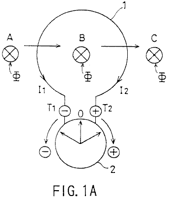
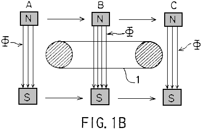
For example, as shown in Fig.1A and Fig.1B, assuming that the magnetic flux phi crossing a circular coil 1 at a perpendicular direction moves in the A to B direction as indicated by the arrow, a current I1 flows in accordance with Faraday's law of electromagnetic induction so that the pointer of a galvanometer 2 swings clockwise (+ direction) and then returns to the zero position. When the magnetic flux phi moves in the direction B to C, a current I2 flows so that the indicator of the galvanometer 2 swings counterclockwise (- direction) and then returns to the zero position.
Generally, an induction generator is constructed in such a way that an electromotive force is induced according to Flemming's right-hand rule by a conductor cutting magnetic flux lines (Fig.1A) or by the magnetic flux lines crossing the conductor (Fig.1B).
A rotor in an induction generator is usually constructed as a one-piece body having alternately disposed North poles and South poles. When there are two magnetic poles, the N-pole and the S-pole are opposite to each other. When there are more than two magnetic poles (for example, four magnetic poles or six magnetic poles etc.), the N-pole and the S-pole alternate, resulting in a N-S-N-S- . . . succession.
In this background, a unipolar induction generator is a special case wherein an electromotive force is generated by a conductor cutting the magnetic flux while moving or rotating, and a direct current is supplied through a slip ring. In other words, a unipolar induction motor is unique in its construction characterised by a non-alternating magnetic field travelling in the same direction.
In the conventional induction generator such as the one described above, improvement in energy conversion efficiency is attained such that the rotor is constructed of a ferrite, or rare-earth, magnet characterised by a high energy product and a small reversing permeability (recoil permeability). Alternatively, the extent of demagnetisation due to generation of a counter magnetic field in an induction coil is reduced allowing the single polarity of the rotor to interact with the stator in forming a magnetic circuit. However, despite these measures, reduction in energy conversion efficiency due to a counter magnetic field of the rotor core, more specifically, due to demagnetisation resulting from the counter magnetic field caused by armature reaction presents a serious problem.
The present invention has been developed in view of the above points, and its object is to provide an induction generator having a pair of magnetic poles of the same polarity opposed to each other with respect to a rotation shaft, wherein a high energy conversion efficiency is attained.
DISCLOSURE OF THE INVENTION
The present invention provides an induction generator having a pair of magnetic poles of the same polarity opposed to each other with respect to a rotation shaft, characterised by comprising:
A rotation shaft driven by external means;
An even number of (more than three) stator cores provided to encircle the rotation shaft, predetermined gaps being provided between the adjacent stator cores;
A first single-opposed polarity rotor provided in the rotation shaft, surrounded by the even number of stator cores, and having first and second magnets magnetised such that the even number of stator cores remain facing a first polarity, the first and second magnets being opposed to each other with respect to the rotation shaft in a cross section;
A second single-opposed-polarity rotor provided in the rotation shaft so as to face the first single-opposed-polarity rotor at a predetermined distance along the rotation shaft, surrounded by the even number of stator cores, and having third and fourth magnets magnetised such that the even number of stator cores remain facing a second polarity which is opposite to the polarity of the first polarity, the third and fourth magnets being disposed opposite to each other with respect to the rotation shaft;
A plurality of windings provided in the even number of stator cores and connected according to a predetermined configuration, characterised in that:
A rotating magnetic field which causes electromagnetic induction in the even number of stator cores successively is created by the first, second, third and fourth magnets when the first and second single-opposed-polarity rotors are rotated; and
Periodic increase and decrease in the number of magnetic flux lines crossing a given winding and associated periodic decrease and increase crossing an adjacent winding causes a periodic electromotive force having a rectangular waveform to be output.
In one aspect of the present invention, the plurality of windings connected according to the predetermined configuration form first and second serial circuits:
The first serial circuit outputs a periodic first electromotive force having a rectangular waveform when a rotating magnetic field which causes electromagnetic induction in the even number of stator cores successively is created by the first, second, third and fourth magnets when the first and second single-opposed-polarity rotors are rotated; and
The second serial circuit outputs a periodic second electromotive force of a rectangular waveform 1800. out of phase with the first electromotive force and having the same period as the first electromotive force, when a rotating magnetic field which causes electromagnetic induction in the even number of stator cores successively is created by the first and second single-opposed-polarity rotors are rotated.
The induction generator of the present invention may also comprise:
Rotation position detecting means for detecting a position of the first and second single-opposed-polarity rotors during their rotation; and
Switching means which alternately causes positive components of the first electromotive force having a rectangular waveform and provided by the first serial circuit, or positive components of the second electromotive force having a rectangular waveform and provided by the second serial circuit to be output at intervals of an electrical angle of 1800.
In another aspect of the present invention, the plurality of windings comprise a first winding provided in a first stator core of the even number of stator cores, a second winding provided in a second stator core adjacent to the first stator core so as to wind in a direction opposite to a direction in which the first winding is provided, a third winding provided in a third stator core adjacent to the second stator core so as to wind in the same direction as the first winding, a fourth winding provided in a fourth stator core adjacent to the third stator core so as to wind in a direction opposite to a direction in which the third winding is provided, the first through fourth windings being connected with each other according to a predetermined configuration.
In still another aspect of the present invention, the first serial circuit comprises a first winding provided to wind in a first direction in a first stator core of the even number of stator cores, a second winding serially connected to the first winding and provided in a second stator core adjacent to the first stator core so as to wind in a second direction opposite to the first direction, a third winding serially connected with the second winding and provided in a third stator core adjacent to the second stator core so as to wind in the first direction, a fourth winding serially connected to the third winding and provided in a fourth stator core adjacent to the third stator core so as to wind in the second direction; and
The second serial circuit comprises a fifth winding provided to wind in the second direction in the first stator core, a sixth winding serially connected to the fifth winding and provided in the second stator core so as to wind in the first direction, a seventh winding serially connected with the sixth winding and provided in the third stator core so as to wind in the second direction, an eighth winding serially connected to the seventh winding and provided in the fourth stator core so as to wind in the first direction.
In yet another aspect of the present invention, the first through fourth magnets are arc-shaped; and
the even number of stator cores have arc-shaped cross sections.
In still another aspect of the present invention, the arc-shaped first through fourth magnets and the stator cores which have arc-like cross sections have an almost identical circumferential length.
BRIEF DESCRIPTION OF THE DRAWINGS
Fig.1A and Fig.1B are diagrams explaining the principle of an induction generator;
Fig.2A and Fig.2B are diagrams showing a first embodiment of the present invention;
Fig.3A and Fig.3B are diagrams showing a single-opposed-polarity rotor 11N according to the first embodiment of the present invention;
Fig.4A and Fig.4B are diagrams showing a single-opposed-polarity rotor 11S according to the first embodiment of the present invention;
Fig.5A, Fig.5B and Fig.5C are diagrams showing how wirings are connected with each other according to the first embodiment of the present invention;
Fig.6A is a diagram schematically showing how a rotating magnetic field according to the first embodiment crosses windings 7c-10c;
Fig.6B shows a magnetic path;
Fig.7 is a diagram showing a waveform of an output voltage according to the first embodiment;
Fig.8A and Fig.8B are diagrams showing a second embodiment of the present invention;
Fig.9 is a diagram showing how wirings are connected with each other according to a second embodiment; and
Fig.10 is a diagram showing a waveform of an output voltage according to the second embodiment.
BEST MODE FOR CARRYING OUT THE INVENTION
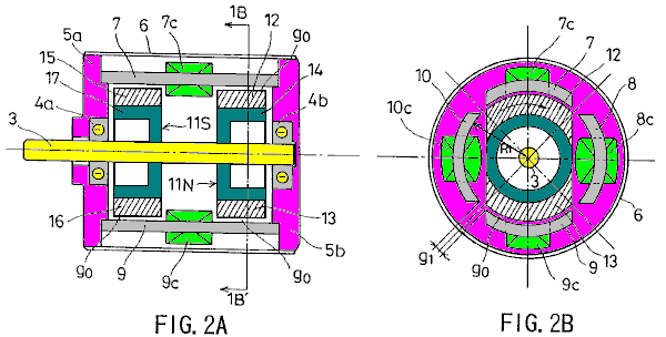
Fig.2A and Fig.2B show a first embodiment of the present invention. Specifically, Fig.2A is a longitudinal sectional view and Fig.2B is a cross-sectional view taken in the line 1B-1B' of Fig.2A.
Referring to Fig.2A and Fig.2B, 3 indicates a rotation shaft formed of a non-magnetic material and driven by an external means; 4a and 4b bearings for supporting the rotation shaft 3; 5a and 5b are flanges provided with the bearings 4a and 4b, respectively; and 6 is a cylindrical case cover for accommodating the flanges 5a and 5b.
Stator cores 7, 8, 9 and 10 are arranged so as to encircle the rotation shaft 3, equidistant gaps g1 being provided between the adjacent stator cores. Each of the stator cores 7, 8, 9 and 10 has the same arc-like cross section.
A single-opposed-polarity N-pole rotor 11N and a single-opposed-polarity S-pole rotor 11S are provided on the rotation shaft 3 so as to be opposite to each other. The single-opposed-polarity rotors 11N and 11S are surrounded by the stator cores 7, 8, 9 and 10, a small rotation gap g0 being provided between the single-opposed-polarity rotor and the stator core.
Referring to Fig.2B, windings 7c and 9c are provided clockwise around the stator cores 7 and 9, respectively. Windings 8c and 10c are wound counterclockwise around the stator cores 8 and 10, respectively. The windings 7c, 8c, 9c and 10c are connected with each other in a configuration described later.

Fig.3A and Fig.3B show the single-opposed-polarity rotor 11N. Specifically, Fig.3A is a longitudinal sectional view, and Fig.3B is a cross-sectional view. The single-opposed-polarity rotor 11N has arc-shaped magnets 12 and 13 which are 1800 displaced from each other and are magnetised such that their surfaces which face the stator cores 7-10 are N-poles while their inner surfaces are S-poles. The arc-shaped magnets 12 and 13 are configured to match the outline of the stator cores 7, 8, 9 and 10. Referring to Fig.3B, the symbols N and N' are used so as to differentiate between the magnets 12 and 13.
A rotor piece 14 is positioned so as to connect the arc-shaped magnets 12 and 13. The rotor piece 14 is magnetised by the arc-shaped magnets 12 and 13 so that it’s surfaces which face the arc-shaped magnets 12 and 13 are S-poles and is formed of a substance (for example, a silicon steel) constructed of a low carbon steel having mixed therein several percent of non-ferrous metal subjected to a forging-cast process. The iron core embodied by the rotor piece 14 thus constructed is characterised by a well-balanced magnetic field where the permeability approximates a peak value in a unipolar magnetic field that the iron core presents to its surroundings.
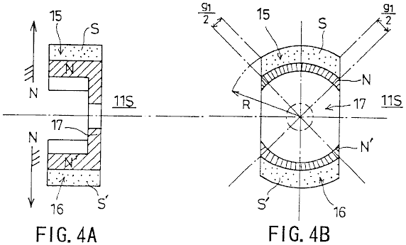
Fig.4A and Fig.4B show the single-opposed-polarity rotor 11S. Specifically, Fig.4A is a longitudinal sectional view, and Fig.4B is a cross-sectional view.
The single-opposed-polarity rotor 11S has arc-shaped magnets 15 and 16 which are 1800 displaced from each other and are magnetised such that the surfaces thereof facing the stator cores 7-10 are S-poles while their inner surfaces are N-poles. The arc-shaped magnets 15 and 16 are configured to match the outline of the stator cores 7, 8, 9 and 10.
A rotor piece 17 is positioned so as to connect the arc-shaped magnets 15 and 16. The rotor piece 17 is magnetised by the arc-shaped magnets 15 and 16 so that it’s surfaces which face the arc-shaped magnets 15 and 16 are N-poles. The rotor piece is made from a substance constructed from a low carbon steel having mixed in it, several percent of non-ferrous metal subjected to a forging-cast process. The iron core embodied by the rotor piece 17 thus constructed is characterised by a well-balanced magnetic field where the permeability approximates a peak value in a unipolar magnetic field that the iron core presents to its surroundings.
The arc-shaped magnets 12, 13, 15 and 16 have the same circumferential length, which is also equal to the length of the arc formed by the circumference of the stator cores 7, 8, 9 and 10. More specifically, this length is obtained by dividing the entire hypothetical circumference minus the four g1 gaps by four. Referring to Fig.2A and Fig.2B, the rotation gap g0 is equal to R1 - R, where R1 is a distance between the centre of the rotation shaft 3 and the inner surface of the stator cores 7-10, and R is a distance between the centre of the rotation shaft 3 and the outer surface of the single-opposed-polarity rotors 11N and 11S, as indicated in Fig.3B and Fig.4B.


Fig.5A, Fig.5B and Fig.5C, show how the wirings are connected with each other. T1 indicates the beginning of a winding, T2 the end of a winding, and 18 and 19 output terminals. More specifically, Fig.5A shows a serial connection configuration, Fig.5B a serial-parallel connection configuration, and Fig.5C a parallel connection configuration. The serial connection configuration allows the electromotive force induced in the windings to be added together and provides a high-voltage output. The parallel connection configuration allows currents resulting from the electromotive force induced in the windings to be added together and provides a large-current output.
A description will now be given, with reference to Fig.6A, Fig.6B and Fig.7, of power generation operation of the serial connection configuration.
Fig.6A is a diagram showing schematically how the rotating magnetic field provided by the single-opposed-polarity rotors 11S and 11N crosses windings 7c-10c. Fig.6B shows a magnetic path.
Referring to Fig.6A, Phi1 and Phi2 indicate rotating magnetic flux rotating along the circumference 2Pi x R. Fig.6B shows the arc-shaped magnets 12 and 15 directly opposite the stator core 7 over their entire length, and the arc-shaped magnets 13 and 16 directly opposite the stator core 9 over their entire length.
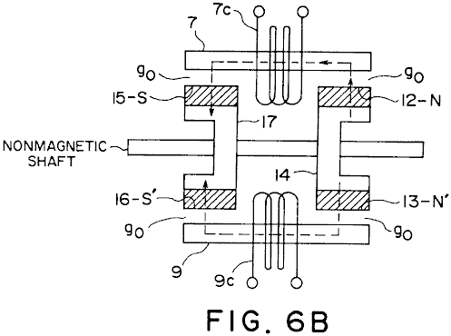
As shown in Fig.6B, the magnetic flux Phi1 forms a magnetic path as follows:
The rotor piece 14 (S) - the arc-shaped magnet pole 12 (N) - stator core 7 - the rotation gap g0 - the arc-shaped magnet 15 (S) - the rotor piece 17 (N).
The magnetic flux Phi2 forms a magnetic path as follows:
The rotor piece 14 (S) - the arc-shaped magnet 13 (N) - the rotation gap g0 - the stator core 9 - the rotation gap g0 - the arc-shaped magnet 16 (S) - the rotor piece 17 (N).
Thus, a parallel magnetic path is formed. In this state, the magnetic flux Phi1 crosses the winding 7c, and the magnetic flux Phi2 crosses the winding 9c.
A description focused on the rotation of the magnetic flux Phi1 is given. Specifically, a description will be given of a change in the way the magnetic flux Phi1 crosses the windings.

Referring to a waveform of an output voltage shown in Fig.7, the entirety of the magnetic flux Phi1 crosses the winding 10c at a time t1. At a time t2, the entirety of the magnetic flux Phi1 crosses the winding 7c. At a time t3, the entirety of the magnetic flux Phi1 crosses the winding 8c. At a time t4, the entirety of the magnetic flux Phi1 crosses the winding 9c. At a time t5, the entirety of the magnetic flux Phi1 crosses the winding 10c. In this way, the magnetic flux Phi1 rotates at a constant speed during a time T, in a clockwise direction in Fig.6A.
Between the time t1 and the time t2, an electromotive force having a descending triangular waveform, indicated by I in Fig.7, is generated in the winding 10c due to a decrease in the number of magnetic flux lines of the magnetic flux Phi crossing the winding 10c. An electromotive force having an ascending triangular waveform, indicated by I' in Fig.6, is generated in the winding 7c due to an increase in the number of magnetic flux lines of the magnetic flux Phi crossing the winding 7c. Accordingly, a positive rectangular waveform obtained by the sum of these triangular waveforms is output to the output terminals 18 and 19.
Between the time t2 and the time t3, an electromotive force having an ascending triangular waveform, indicated by II in Fig.7, is generated in the winding 7c due to a decrease in the number of magnetic flux lines of the magnetic flux Phi crossing the winding 7c. An electromotive force having a descending triangular waveform, indicated by II' in Fig.7, is generated in the winding 8c due to an increase in the number of magnetic flux lines of the magnetic flux Phi crossing the winding 8c. Accordingly, a negative rectangular waveform obtained by the sum of these triangular waveforms is output to the output terminals 18 and 19.
Between the time t3 and the time t4, an electromotive force having a descending triangular waveform, indicated by III in Fig.7, is generated in the winding 8c due to a decrease in the number of magnetic flux lines of the magnetic flux Phi of the magnetic flux Phi crossing the winding 8c. An electromotive force having an ascending triangular waveform, indicated by III' in Fig.7, is generated in the winding 9c due to an increase in the number of magnetic flux lines of the magnetic flux Phi crossing the winding 9c. Accordingly, a positive rectangular waveform obtained by the sum of these triangular waveforms is output to the output terminals 18 and 19.
Between the time t4 and the time t5, an electromotive force having an ascending triangular waveform, indicated by IV in Fig.7, is generated in the winding 9c due to a decrease in the number of magnetic flux lines of the magnetic flux Phi crossing the winding 9c. An electromotive force having a descending triangular waveform, indicated by IV' in Fig.7, is generated in the winding 10c due to an increase in the number of magnetic flux lines of the magnetic flux Phi crossing the winding 10c. Accordingly, a negative rectangular waveform obtained by the sum of these triangular waveforms is output to the output terminals 18 and 19.
While the magnetic flux Phi1 makes one rotation, an electromotive force having a synthesised rectangular waveform and a period of T/2 is output, as shown in Fig.7. Since the magnetic flux Phi2 also makes one rotation while the magnetic flux Phi1 makes one rotation and produces an output of an electromotive force having a similar rectangular waveform, the magnitude of the electromotive force obtained between the terminals 18 and 19 is actually double that indicated in Fig.7.
In this way, this embodiment makes it possible to cancel a counter magnetic field and provide an induction generator having a pair of magnetic poles of the same polarity opposed to each other with respect to a rotation shaft and characterised by a high energy conversion efficiency. Our operating practice has confirmed that the generator having the construction of this embodiment provides an energy conversion efficiency which is high enough to require only 1/5.2 of the driving torque for the conventional generator.
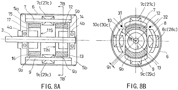
Fig.8A and Fig.8B show a second embodiment of the present invention. Specifically, Fig.8A is a longitudinal sectional view, and Fig.8B is a cross-sectional view taken in the line 7B-7B' of Fig.8A.
Referring to Fig.8A and Fig.8B, 3 indicates a rotation shaft formed of a non-magnetic material and driven by an external source; 4a and 4b are bearings which support the rotation shaft 3, 5a and 5b are flanges housing the bearings 4a and 4b, and 6 is a cylindrical case cover for accommodating the flanges 5a and 5b.
Stator cores 7, 8, 9 and 10 are arranged so as to encircle the rotation shaft 3, equidistant gaps g1 being provided between the adjacent stator cores. Each of the stator cores 7, 8, 9 and 10 has a same arc-like cross section.
A single-opposed-polarity N-pole rotor 11N and a single-opposed-polarity S-pole rotor 11S are provided on the rotation shaft 3 so as to be opposite to each other. The single-opposed-polarity rotors 11N and 11S are surrounded by the stator cores 7, 8, 9 and 10 a small rotation gap g0 being provided between the single-opposed-polarity rotor and the stator core.
Referring to Fig.8B, windings 7c and 9c are provided clockwise around the stator cores 7 and 9, respectively. Windings 27c and 29c are provided counterclockwise around the stator cores 7 and 9, respectively. Windings 8c and 10c are provided counterclockwise in the stator cores 8 and 10, respectively. Windings 28c and 30c are wound clockwise around the stator cores 8 and 10, respectively. The windings 7c, 8c, 9c, 10c, 27c, 28c, 29c and 30c are connected with each other according to a configuration described later.
A magnetic sensor (for rotation position detection) 31 is provided between the stator cores 7 and 10, and a magnetic sensor (for rotation position detection) 32 is provided between the stator cores 7 and 8. The magnetic sensors 31 and 32 detect the magnetic field so as to determine the position of the single-opposed-polarity rotors 11N and 11S during their rotation.
The single-opposed-polarity rotors 11N has a configuration as shown in Fig.3A and Fig.3B, and the monopole rotor 11S has a configuration as shown in Fig.4A and Fig.4B.
The single-opposed-polarity rotor 11N has arc-shaped magnets 12 and 13 which are 1800 displaced from each other and are magnetised such that their surfaces facing the stator cores are N-poles while their respective inner surfaces are S-poles. The arc-shaped magnets 12 and 13 are configured to match the outline of the stator cores 7, 8, 9 and 10.
A rotor piece 14 is positioned so as to connect the arc-shaped magnets 12 and 13. The rotor piece 14 is constructed from a low-carbon steel having several percent of non-ferrous metal, using a forging-cast process. The iron core rotor piece 14 constructed by this means, has a well-balanced magnetic field where the permeability approximates a peak value in a unipolar magnetic field that the iron core presents to its surroundings.
The single-opposed-polarity rotor 11S has arc-shaped magnets 15 and 16 which are positioned 1800 apart from each other and are magnetised so that their surfaces which face the stator cores are S-poles while their inner surfaces are N-poles. The arc-shaped magnets 15 and 16 are shaped and positioned so as to match the outline of the stator cores 7, 8, 9 and 10.
A rotor piece 17 is positioned so as to connect the arc-shaped magnets 15 and 16. The rotor piece 17 is constructed from a low-carbon steel having several percent of non-ferrous metal, using a forging-cast process. The iron core rotor piece 17 constructed by this means, has a well-balanced magnetic field where the permeability approximates a peak value in a unipolar magnetic field which the iron core presents to its surroundings.
The arc-shaped magnets 12, 13, 15 and 16 have the same circumferential lengths, which is equal to the length of the arc formed by the circumference of the stator cores 7, 8, 9 and 10. More specifically, this length is obtained by dividing by four, the entire hypothetical circumference minus the four gaps g1. Referring to Figs. 3A, 3B, 4A, 4B and 8, the rotation gap g0 is equal to R1 -R.

Fig.9 shows how the wirings are connected with each other. T1 indicates the beginning of a winding, T2 the end of a winding, and 18 and 19 are the output terminals.
Two serial circuits are formed out of the windings. Switches SW1 and SW2 are used for selection of the respective serial circuits. A switching control circuit 40, which processes a detection signal from the magnetic sensors 31 and 32, drives the switches SW1 and SW2 selectively in accordance with the detection signal.
As shown in Fig.9, the first serial circuit comprises the winding 7c provided clockwise in the stator core 7, the winding 8c serially connected with the winding 7c and provided counterclockwise in the stator core 8 adjacent to the stator core 7; the winding 9c serially connected with the winding 8c and provided clockwise in the stator core 9; and the winding 10c serially connected with the winding 9c and provided counterclockwise in the stator core 10 adjacent to the stator core 9.
As shown in Fig.9, the second serial circuit comprises the winding 27c provided counterclockwise in the stator core 7; the winding 28c serially connected with the winding 27c and provided clockwise in the stator core 8; the winding 29c serially connected with the winding 28c and provided counterclockwise in the stator core 9; and the winding 30c serially connected with the winding 29c and provided clockwise in the stator core 10.
According to the construction described above, a rotating magnetic field which causes electromagnetic induction in the stator cores 7-10 successively is created by the arc-shaped magnets 12, 13, 15 and 16 when the single-opposed-polarity rotors 11N and 11S are rotated. As has been already explained with reference to Fig.6A, Fig.6B and Fig.7, as the magnetic flux lines crossing one of the windings 7c-10c increase in number, the magnetic flux lines crossing the adjacent one of the windings 7c-10c decrease in number. That is, the magnetic flux lines periodically increase and decrease with respect to a given winding so that a first electromotive force, having a rectangular waveform similar to the one shown in Fig.7 and a period that is 1/2 the period of the rotation, is output from the first serial circuit (7c-10c).
As the magnetic flux lines crossing one of the windings 27c-30c increase in number, the magnetic flux lines crossing the adjacent one of the windings 27c-30c decrease in number. That is, the magnetic flux lines periodically increase and decrease with respect to a given winding so that a second electromotive force of a rectangular waveform 1800 out of phase with the first electromotive force and having the same period as the first electromotive force is output from the second serial circuit (27c-30c). That is, the second electromotive force is 1800 out of phase with the electromotive force shown in Fig.7.
Referring to Fig.10, in accordance with the detection signal from the magnetic sensors 31 and 32, the switches SW1 and SW2 effect switching at 900 intervals. By that means, the positive components I and III of the first electromotive force having a rectangular waveform and provided from the first serial circuit, and the positive components II and IV of the second electromotive force having a rectangular waveform and provided from the second serial circuit are alternately selected at 1800 intervals and output to the output terminals 18 and 19.
This means that, this embodiment ensures a high-efficiency energy conversion wherein a counter magnetic field is cancelled, and a DC electromotive force having a positive level is properly synthesised and output. It is of course possible to synthesise and output a negative DC electromotive force by shifting the switching timing by 1800.
INDUSTRIAL APPLICABILITY
As has been described, according to the present invention, the rotation of the first and second single-opposed-polarity rotors generates a rotating magnetic field which causes an induction in an even number of stator cores successively. As the magnetic flux lines crossing one of the first-through-fourth windings increase in number, the magnetic flux lines crossing the adjacent one of the first-through-fourth windings decrease in number. That is, the magnetic flux lines periodically increase and decrease with respect to a given winding. The electromotive force generated as the magnetic flux lines crossing a winding increase in number and the electromotive force generated as the magnetic flux lines crossing an adjacent winding decrease in number are synthesised so that a periodic AC electromotive force having a rectangular waveform is generated out of the synthesis and output. In this way, a high-efficiency energy conversion wherein a counter magnetic field is cancelled is provided.
According to the first serial circuit of the present invention, the rotation of the first and second single-opposed-polarity rotors generates a rotating magnetic field which causes an induction in an even number of stator cores successively. As the magnetic flux lines crossing one of the first through fourth windings increase in number, the magnetic flux lines crossing the adjacent one of the first through fourth windings decrease in number. That is, the magnetic flux lines periodically increase and decrease in a given winding. Accordingly, the first electromotive force having a rectangular waveform is output. According to the second serial circuit, as the magnetic flux lines crossing one of the fifth-through-eighth windings increase in number, the magnetic flux lines crossing the adjacent one of the fifth-through-eighth windings decrease in number. That is, the magnetic flux lines periodically increase and decrease in a given winding. Accordingly, the second electromotive force 1800 out of phase with the first electromotive force and having the same period as the first electromotive force is output. In accordance with the detection signal from the rotation position detecting means, the switching means selectively causes the positive components of the first electromotive force provided by the first serial circuit, or the positive components of the second electromotive force provided by the second serial circuit to be output at 1800 intervals. In this way the DC electromotive force is synthesised and output. This results in a high-efficiency energy conversion where a counter magnetic field is cancelled.
In addition to extensive applications in power plants, ships, aircraft etc., the present invention may find household applications or may be conveniently adapted for leisure uses.
LARRY JAMISON: ELECTRICAL ENERGISER
Patent Application EU 82,400,992.2
22nd December 1982
Inventor: Larry T. Jamison
ENERGY SOURCE EMPLOYING ELECTRICAL ENERGISER
This patent application shows the details of a device which it is claimed, can produce electricity without the need for any fuel. It should be noted that while construction details are provided which imply that the inventor constructed and tested several of these devices, this is only an application and not a granted patent.
ABSTRACT
An energy producing system is provided which produces energy for use, for example, in an electric vehicle or in a home power plant. The system includes an electrical energiser (60) including a double-wound rotor and a double-wound stator, for producing electrical energy which is stored in the system, e.g. in a battery (66) storage arrangement, which provides initial energisation of the system. the stored energy is supplied to an electric motor (68) which drives the energiser (60) to thereby create additional energy. the energiser is able to supply the needs of the system as well as to power a load.
BACKGROUND OF THE INVENTION
The present invention relates to energy producing systems and, more particularly, to an electrical energiser-motor system for providing energy, e.g., for an automotive vehicle or as part of a home energy plant.
With the advent of the so-called “energy crisis” and the consequent search for alternative energy sources to substitute for oil, considerable attention has been focused on automotive vehicles as chief users of oil products. One aspect of this search has fostered renewed interest in electrically driven vehicles such as electric cars and the like. A principal shortcoming of prior-art electrical vehicles has been the need to recharge the batteries which provide the power for the electrical motor drive system.
The present invention overcomes this problem through the provision of an electrical energiser-motor system which produces more energy than is expended, thereby enabling the excess energy to be stored in the battery system, to be drawn upon as required. Thus, the need for recharging of the batteries associated with conventional electrical vehicles is eliminated with the system of this invention. It should be noted that while the system of the invention has enormous potential in connection with its use in electrical vehicles, the system is clearly not limited to such use and would obviously be advantageous when used, for example, as the energy source for a home energy plant, as well as in many other applications.
In accordance with the invention, and energy producing system of the type described above is provided which comprises and electrical “energiser” comprising at least one double-wound stator and at least one double-wound shaft-mounted rotor located within a housing, electrical energy being collected from the rotor through a suitable electrical take-off device and being available for utilisation by the system, and an electric motor, powered by the energiser for driving the rotor shaft of the energiser. A battery arrangement is initially used to supply energy to the system and, as stated above, the excess energy generated by the energiser over and above that required by the system and the system load, is stored through charging of the batteries. The motor includes an armature with a plurality of winding slots in it and a plurality of windings being wound into two circumferentially spaced slots in the armature, i.e. such a winding is wound through a first slot (e.g. slot 1) and returned through a second spaced slot (e.g. slot 5). depending on the energy demands, the energiser may include a pair of stators and rotors, with the rotors being mounted on a common shaft. The motor is preferably energised through an arrangement of a commutator and plural brushes, while a slip ring and associated brushes connected to an output bridge circuit form the energy take-off for the energiser.
Other features and advantages of the invention will be shown in the detailed description of the preferred embodiments which follows.
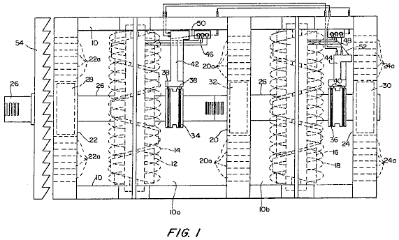
Fig.1 is a partially sectioned elevational view of the electrical “energiser” of the invention.
Fig.2 is a block diagram of the overall energy-producing system of the invention
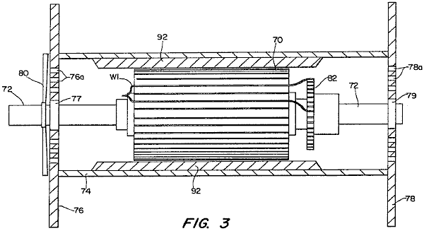
Fig.3 is a partially sectioned side elevational view of a modified electrical motor constructed in accordance with the invention.
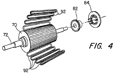
Fig.4 is an exploded perspective view of the basic components of the motor of Fig.3.
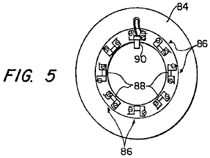
Fig.5 is an end view of the brush holder also illustrated in Fig.4.

Fig.6 and Fig.7 show details of the winding pattern of the motor of Fig.3.
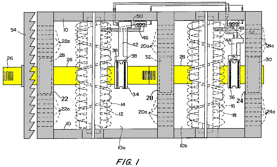
Referring to Fig.1, a preferred embodiment of the “energiser” device of the invention is shown. The device includes a housing 10, in which are located, in a first chamber or compartment 10a, a first rotor 12 and a first stator 14 and, in a second compartment 10b, a second rotor 16, and a second stator 18. It should be noted that although two stator-rotor combinations are used in this embodiment, a single stator-rotor combination can be used for some applications. Housing 10 is divided into the compartments 10a and 10b, by a centre plate 20 and it includes a pair of end plates 22 and 24. Both the rotors 12, 16 and the stators 14, 18 are double wound and the rotors 12, 16 are nested inside their respective stators 14 and 18 and mounted for rotation on a common shaft 26. Shaft 26 extends longitudinally through housing 10 and is mounted on bearings 28 and 30, supported by end plates 22 and 24, and a further bearing 32 which is supported by central plate 20.
A pair of slip rings 34 and 36, are mounted on shaft 26 and connect with their corresponding brush pairs 38 and 40.
Slip rings 34 and 36 are connected to rotors 12 and 16 respectively, and permit the current flowing in the rotor windings to be collected through the associated pairs of brushes 38 and 40. Brush pairs 38 and 40 are mounted on respective brush holders 42 and 44. The terminals of respective bridge circuits 46 and 48 are connected to stators 14 and 18, while conversion bars 50 and 52 are connected to brush holders 42 and 44, as indicated.
A cooling fan 54, is also mounted on shaft 26 and a plurality of apertures 201, 22a and 24a are provided in centre plate 20 and end plates 22 and 24, to promote cooling of the device. The energiser of Fig.1 is preferably incorporated in a system such as shown in a highly schematic manner in Fig.2 where the output of the energiser is used to supply the energy for driving a motor. To this end, the energiser, which is denoted by 60 in Fig.2, is connected through a regulator 62, to battery charger 64 for batteries 66 connected to a motor 68. These batteries 66 are used to provide the initial energisation of the system as well as to store energy produced by the energiser 60. It will be understood that the energiser 60 provides energy enough to power motor 68 (which, in turn, drives energiser 60 through rotation of shaft 26) as well as to provide storage for energy in the system. It will also be appreciated that the system illustrated schematically in Fig.2 includes suitable controls (switches, rheostats, sensors, etc.) to provide initial energisation as well as appropriate operational control of the system.
In a preferred embodiment, motor 68 is of the form shown in Fig.3. As illustrated, the motor is of a generally conventional form (with exceptions noted below) and comprises an armature 70, mounted on a shaft 72 within housing 74. Housing 74 includes a pair of end plates 76 and 78, which mount shaft bearings 77 and 79. Apertures 76a and 78a are provided in end plates 76 and 78 and a cooling fan 80 is mounted on shaft 72 to provide cooling.
A commutator 82 is also mounted on shaft 72, and co-operates with associated brushes (not shown in Fig.1), to conduct current to the windings of armature 70. This co-operation is shown best in Fig.4 which is an exploded view, illustrating the armature 70, commutator 82 and a brush holder 84.
As shown in Fig.5, the brush holder 84 includes eight brush mounts 86, each of which defines a slot 88 in which a pair of brushes is mounted. One brush 90 is shown in Fig.5, it being understood that two such brushes are mounted in each slot 88 so that sixteen brushes are required.
The motor of Fig.3 to Fig.6 includes eight pole shoes (not shown) which are secured to housing 74 and which serve to mount eight field coils or windings 92 (see Fig.3 and Fig.4) spaced out around the periphery of armature 72.
An important feature of the motor of Fig.3 to Fig.6 concerns the manner in which the windings for armature 70 are wound. As illustrated in Fig.3, Fig.6 and Fig.7, a typical winding W1 is wound in two slots, with the illustrated winding being doubled back and continuing from armature slot S1 to armature slot S5 (see Fig.3 and Fig.6). Similarly, the winding in slot S2 continues to slot S6, the winding of slot S3 continues to slot S7, and so on for the forty-nine windings.
In a specific preferred embodiment, the motor described above is a 48-volt, 412 horsepower motor having a top operating speed of 7,000 rpm. A rheostat control (not shown) is used to control the input voltage and, as discussed above, the motor is powered from the energiser of Fig.1. It will be appreciated that the energy take-off from the system is preferably from the output shaft of the motor, although the electrical energy may also be tapped off from the energiser output.
Although the invention has been described in relation to exemplary embodiments, it will be understood by those skilled in the art, that variations and modifications can be effected in these embodiments without departing from the scope and spirit of the invention.
TERUO KAWAI: ELECTRIC MOTOR
MOTIVE POWER-GENERATING DEVICE
Please note
that this is a re-worded excerpt from this patent. It describes a motor which has an output
power greater than its input power.
SUMMARY OF THE INVENTION
It is an object of the invention to provide a motive power generation device in which the occurrence of a force acting in a direction opposite to the direction of movement of a rotor and/or a stator is prevented, so as to permit efficient use of electric energy to be applied to electromagnets, as well as magnetic energy generated by a permanent magnet.
In order to achieve the above object, the first invention comprises a permanent
magnet disposed around a rotational output shaft which is mounted on a bearing,
a magnetic body positioned concentrically with the permanent magnet for
rotation with the output shaft, the magnetic body being subjected to the
magnetic flux of the permanent magnet, a plurality of electromagnets
permanently mounted on the support member so that they are spaced a
predetermined distance around the periphery of the magnetic material, each magnetic
circuit of the electromagnets being independent of one another and the
excitation change-over mechanism of the electromagnets which can sequentially
magnetise one of the electromagnets which is positioned forward, with regard to
a rotational direction, of the output shaft, so as to impart to the
electromagnet a magnetic polarity magnetically opposite to that of the magnetic
pole of the permanent magnet, whereby a magnetic flux passing through the
magnetic body converges in one direction thereby applying a rotational torque
to the output shaft.
According to the first invention, when one of the electromagnets which is
positioned ahead in the rotational direction of the rotational output shaft, a
magnetic field created by the excited electromagnet and a magnetic field
created by the permanent magnet interact with each other. Thus, the magnetic
flux passing through the magnetic body converges toward the exited
electromagnet, so as to rotate the rotational output shaft by a predetermined
angle toward the excited electromagnet. When the rotational output shaft has
been rotated by the predetermined angle, the above excited electromagnet is
de-magnetised, and another electromagnet currently positioned ahead with
respect to the rotational direction of the rotor output shaft is excited or
magnetised. Sequential excitation of the electromagnets in the above manner
permits rotation of the output shaft in a predetermined direction. In this regard, it should be noted that the
electromagnets are excited so as to have a magnetic polarity opposite to that
of the magnetic pole of the permanent magnet and that the magnetic circuit of
the excited electromagnets is independent from those of adjacent
electromagnets. Thus, the magnetic flux
generated by the excited electromagnet is prevented from passing through
magnetic circuits of adjacent electromagnets, which, if it occurs, might cause
the electromagnets to be magnetised to have the same polarity as that of the
magnetic pole of the permanent magnet.
Accordingly, no objectionable force will be generated which might
interfere with rotation of the output shaft.
In order to achieve the above object, the second invention comprises a
permanent magnet mounted on a movable body arranged movably along a linear
track, a magnetic body mounted on the permanent magnet, the magnetic body being
subjected to a magnetic flux of the permanent magnet, a plurality of
electromagnets spaced an appropriate distance along the linear track, the
electromagnets having magnetic circuits which are independent of one another
and the excitation mechanism arranged to magnetise each of the electromagnets
sequentially when each is positioned forward of the movable body, (with respect
to the direction of movement) so as to impart to the excited electromagnet a
magnetic polarity opposite to that of the magnetic pole of the permanent
magnet, whereby a magnetic flux passing through the magnetic body converges in
a predetermined direction so as to cause linear movement of the movable body.
According to the second invention, when the electromagnet positioned ahead of
the forward end of the movable body with regard to the direction of the
movement of the movable body is excited, a magnetic field generated by the
excited electromagnet and magnetic field generated by the permanent magnet
interact with each other. Thus, a magnetic flux passing through the magnetic
body converges toward the excited electromagnet, so as to displace the movable
body a predetermined distance toward the excited electromagnet. When the movable
body has been moved the predetermined distance, the movable body is positioned
below the above excited electromagnet, and another electromagnet is positioned
ahead of the forward end of the movable body. When this occurs, excitation of
the electromagnet positioned above the movable body is interrupted, and
excitation of the electromagnet now positioned ahead of the forward end of the
movable body is initiated. Sequential
excitation of the electromagnets in the above manner permits movement of the
movable body in a predetermined direction
It should be noted that no objectionable force which would interfere
with movement of the movable body is created for the same reason as that
explained in relation to the first invention.
BRIEF DESCRIPTION OF THE DRAWINGS
Fig.1 is a front elevational view, partly in section and partly omitted, of a motor according to a first embodiment of the invention;
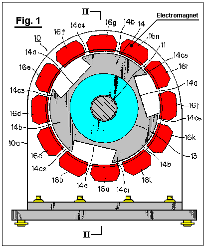
Fig.2 is a sectional view along line II--II in Fig.1;
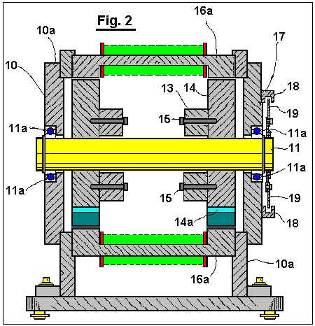
FIG. 3
is a rear elevational view of the motor provided with a light shield plate
thereon;

Fig.4A through Fig.4H illustrate operation of the motor when the electromagnets are excited or magnetised;
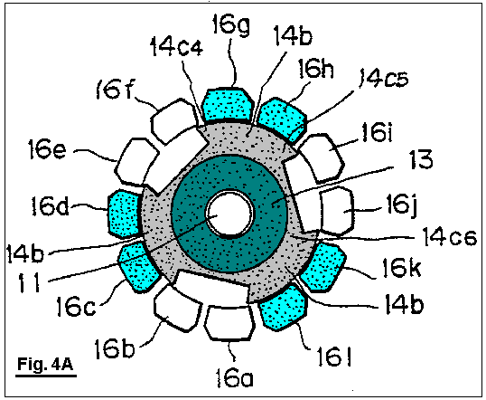
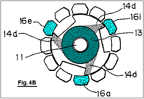
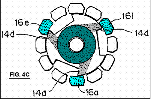
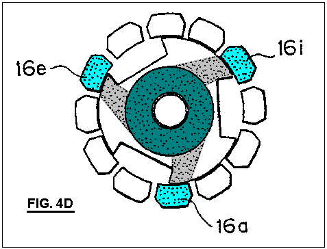
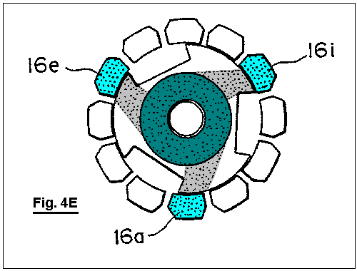
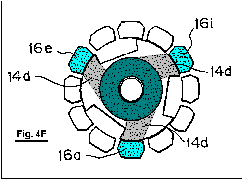
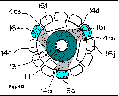
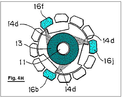
Fig.5A is an illustrative view showing a magnetic path of magnetic flux created by a permanent magnet of the motor when the electromagnets are not magnetised;
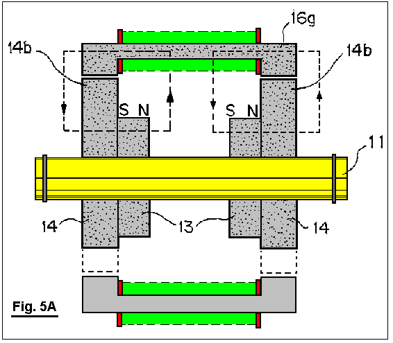
Fig.5B is an illustrative view showing a magnetic path of magnetic flux created by the permanent magnet of the motor, as well as magnetic path of magnetic flux created by the electromagnets;
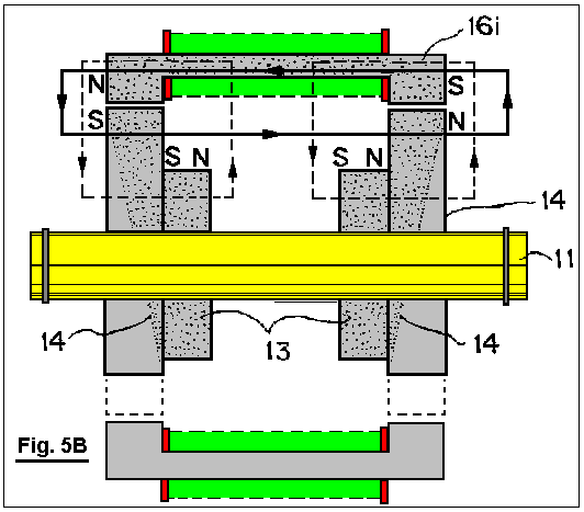
FIGS. 6
through 9 are cross-sectional view illustrating a modified form the motor;
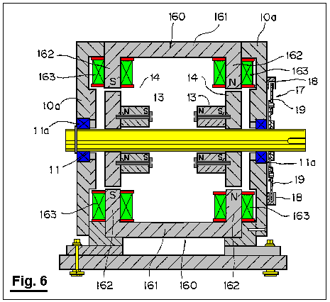
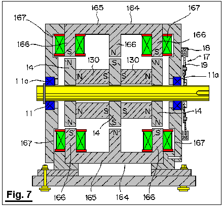
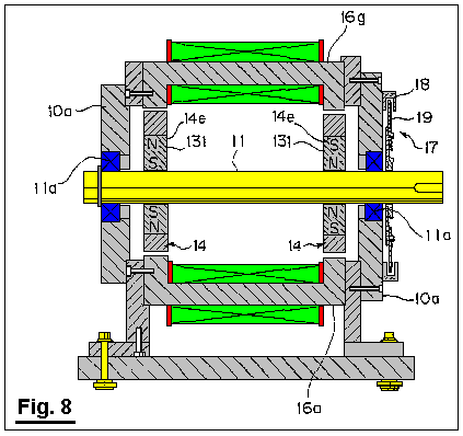
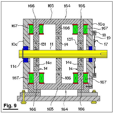
FIGS. 10A through 10C are cross-sectional views illustrating operation of the modified motor;
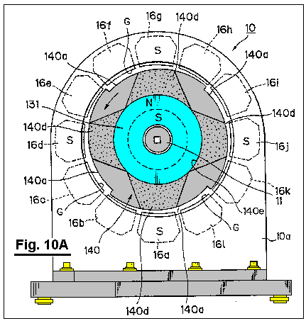
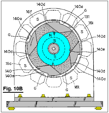
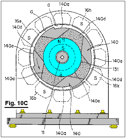
FIGS. 11A through 11H are illustrative diagrams showing operation of a motor in a form of a linear motor according to a second embodiment of the invention;
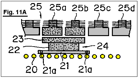
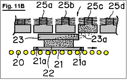
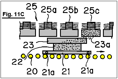
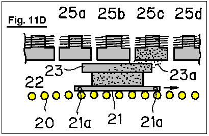
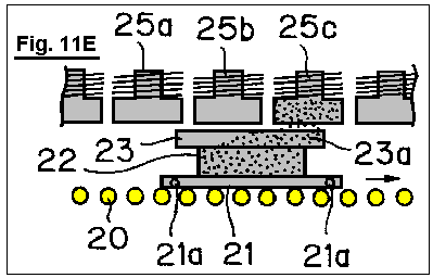
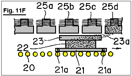
DETAILED DESCRIPTION OF PREFERRED
EMBODIMENTS
Preferred
embodiments of the invention will be explained in detail below with reference
to the attached drawings.
According to a first embodiment of the invention, a rotational output shaft 11 is mounted in a bearing between
front and rear side plates 10a of a
support member 10 through bearings 11a, as shown in Fig.1 and Fig.2. A ring of permanent magnets 13 are fitted over the opposite ends of
the output shaft, inside the side plates 10a
and these move with the rotor shaft 11. The permanent magnets are magnetised in the
axial direction. A magnetic body 14 is rigidly mounted between each of
the side plates 10a of the rotor
shaft 11 and the permanent magnets 13.
Each of these magnetic bodies 14
has alternate notches 14a and
magnetic teeth 14b. It should be noted that the flux of the
permanent magnets 13 passes through
the respective magnetic bodies 14. For example, Fig.1 shows the magnetic body 14
with three notches 14a and three
magnetic teeth 14b. The permanent magnets 13 and magnetic bodies 14
are positioned co-axially with the rotor output shaft 11. The corresponding
permanent magnets 13 and magnetic
bodies 14 are shown connected
together by bolts 15 so as to form a
rotor 12 which is attached to the
rotational output shaft 11.
It should be noted that the support member 10
and rotational output shaft are both made from a non-magnetic material. The support member 10 may be formed, for example, from stainless steel, aluminium
alloys, or synthetic resins, while the rotational output shaft 11 may be formed from stainless steel,
for example. Thus, the magnetic circuit
formed by the permanent magnet 13
and magnetic body at one axial end of the rotational output shaft 11 and the magnetic circuit formed by
the permanent magnet 13 and magnetic
body at the opposite axial end of the output shaft, are independent of one
another. The magnetic bodies 14 may
be formed from magnetic materials having a high magnetic permeability, such as
various kinds of steel materials, silicon steel plate, permalloys, or the like.
The stator contains electromagnets 16a
through 16l, which are positioned
between the side plates 10a. The
electromagnets are evenly spaced around the magnetic pieces 14 so that they surround the magnetic
bodies. As shown in Fig.1, twelve electromagnets may be used. The magnetic circuit of each of the
electromagnets 16a through 16l is arranged so as to be independent
of each other, so that no flux of a magnetised electromagnet passes through the
iron cores of the adjacent electromagnets.
The iron cores of the electromagnets 16a
through 16l are positioned parallel
to the rotor axis shaft 11, and positioned with only a slight gap between
them and the magnetic bodies 14.
Some of the electromagnets 16a
through 16l are located at a
position corresponding to boundary portions 14c1 through 14c6
between the notch 14a and the
magnetic tooth 14b. For example, as shown in Fig.1, electromagnets 16a,
16b, 16e, 16f, 16i and 16j are
positioned opposite the boundary portions 14c1,
14c2, 14c3, 14c4, 14c5, and 14c6,
respectively.
Fig.5A shows a path of magnetic flux
created by the permanent magnet 13
when the electromagnets are not excited or magnetised, while, Fig.5B shows a path of magnetic flux
created by the permanent magnet 13
and a path of magnetic flux created by the windings of the electromagnets when
the electromagnets are magnetised. As
will be clear from Fig.5A and Fig.5B, both paths of magnetic flux
represent a uni-polar distribution in which N-pole or S-pole evenly appears at
the opposite axial ends. When the electromagnets are magnetised, the magnetic
fields of the permanent magnet and electromagnets co-operate or interact with
each other so as to generate a rotational torque.
Excitation change-over mechanism 17
for sequentially exciting or magnetising the electromagnets 16a through 16l is basically consisted of a conventional excitation circuit for
supplying direct current to each windings of the electromagnets 16a through 16l. In this embodiment, the
change-over portion for changing electric feed to the electromagnets 16a through 16l includes a plurality of optical sensors 18 and a light shield plate 19
for turning the optical sensors ON and OFF as shown in Fig.6.
The optical sensors 18 are spaced
apart from one another with a space between them for permitting the light
shield plate 19 to pass through a
light emitting element and a light receiving element. The optical sensors 18 are disposed in the outer surface of
one of the side plates 10a equally
spaced apart along the circumference, so that they are positioned to correspond
to the electromagnets 16a through 16l (for example, the optical sensor 18 is shown to be disposed in the outer
surface of the rear side plate). The light shielding plate 19 is fixed to the rotational output shaft 11 at the end thereof, the light shielding plate protruding from
the rear side plate 10a on which the
optical sensors are mounted.
According to the illustrated embodiment, when a particular optical sensor 18 is blocked by the light shielding
plate 19, the electromagnet corresponding
to such optical sensor 18 is
supplied with electricity.
The operation of the first embodiment described above will be explained with
reference to Fig.4A through Fig.4H.
When the electromagnets 16a through 16l are not supplied with electricity
by means of the excitation changeover mechanism 17, the electromagnets 16c,
16d, 16g, 16h, 16k and 16l
opposed to the magnetic teeth 14b
with a small gap between them merely serve as a magnetic material disposed
within the magnetic field of the permanent magnet 13 (refer to shaded portion in Fig.4A),
so as to absorb the magnetic teeth 14b,
and the rotor 12 remains stationary.
When the electromagnets 16a, 16e and
16i positioned adjacent to the
boundary portion 14c1, 14c3 and 14c5 formed between the respective
notches 14a and the magnetic teeth 14b are magnetised or excited
simultaneously by means of the excitation change-over mechanism, as shown in Fig.4B, the magnetic field of the
permanent magnet 13 and the magnetic
fields of the electromagnets 16a, 16e
and 16i interact with each other, so
that a magnetic flux 14d passing
through the magnetic body 14
instantaneously converges to the electromagnets 16a, 16e, and 16i. In this way, the rotor 12 is imparted with a rotational torque in a direction in which the
magnetic flux 14d will be widened,
i.e., counterclockwise direction as viewed in Fig.4B.
Fig.4C through Fig.4G illustrate change in the width of the magnetic flux 14d in accordance with rotation of the
rotor 12. When the width of the magnetic flux becomes
maximised, i.e., when only the magnetic teeth 14b are opposed to the electromagnets 16a, 16e and 16i, while
the notches 14a are displaced
completely away from the electromagnets 16a,
16e and 16i, the width of the
magnetic flux 14d is maximised. Thus, an absorption force acting between the
permanent magnet 13 and the
electromagnets 16a, 16e and 16i is maximised. On the other hand, the rotational torque
acting on the rotor 12 becomes zero.
Before the rotational torque acting on the rotor 12 becomes zero, i.e., as the boundary portion 14c1, 14c3 and 14c5
approach another electromagnets 16b, 16f
and 16j positioned ahead of (with
regard to the rotational direction), respectively, the electromagnets 16a, 16e and 16i are demagnetised and the electromagnets 16b, 16f and 16j are
excited or magnetised by means of the excitation change-over mechanism 17. Thus, the magnetic flux 14d converges toward the electromagnets
16b, 16f and 16j, as shown in Fig.4H,
so that a rotational torque acts upon the rotor, as described above.
Then, the electromagnets 16c, 16g
and 16k are excited. When the boundary portion 14c1, 14c3 and 14c5 approach another electromagnets 16d, 16h and 16l
positioned ahead with respect to the rotational direction, in response to
rotation of the rotor 12, the
electromagnets 16c, 16g and 16k are de-magnetised and the
electromagnets 16d, 16h and 16l are energised or excited.
As explained above, sequential excitation or energising of the electromagnets 16a through 16l causes interaction between the magnetic flux of the permanent
magnet 13 and the electromagnets 16a through 16l, whereby a rotational torque is applied to the rotor 12.
When this occurs, a rotational torque is generated between one of the magnetic
poles of the permanent magnet 13 (for
example, N-pole) and the magnetic poles (for example, S-poles) of the
electromagnets 16a through 16l positioned at their respective
axial ends. A rotational torque is also generated between the other magnetic
pole (for example, S-pole) of the permanent magnet 13 and the other magnetic pole (for example, N-pole) of each of the
electromagnets 16a through 16l positioned at the other axial end.
It should be noted that, at one magnetic pole, for example N-pole, of the
permanent magnet 13, certain of the
electromagnets 16a through 16l are magnetised only to S-pole, thus
preventing formation of a magnetic circuit, due to passage of magnetic flux
from the excited electromagnets through either of the adjacent electromagnets,
which tends to bring about N-poles magnetically similar to the permanent magnet
13. It is also noted that, at the
other magnetic pole, for example S-pole, of the permanent magnet 13, certain of the electromagnets are
magnetised only to N-pole, thus preventing formation of a magnetic circuit, due
to passage of magnetic flux from the excited electromagnets through adjacent
electromagnets, which tends to bring about S-poles magnetically similar to the
permanent magnet 13. The magnetic flux of the permanent magnet 13 passes through the magnetic bodies 14 so as to be converged to the excited
electromagnets (refer to the magnetic flux 14d
shown in Fig.4 through Fig.4H), thus forming dead zones,
through which no magnetic flux passes, in the magnetic bodies 14 at a position opposite to the
un-excited electromagnets. Accordingly,
no force is generated which would tend to prevent rotation of the rotor 12.
In view of electric energy applied to the electromagnets 16a through 16l,
substantially all the electric energy applied is used to contribute to the
rotation of the rotor 12. On the other hand, and in view of magnetic
energy of the permanent magnet 18,
all the magnetic energy contributes to the rotation of the rotor 12.
It is also noted that, since the notches 14a
and the magnetic teeth 14b are alternately
disposed in the outer periphery of the magnetic materials 14 in an acute angle configuration seen in Fig.4A to Fig.4H, and
the electromagnets are disposed at a position each corresponding to the
boundary portions between the notches and the magnetic teeth, it is possible
for the line of the magnetic force, generated in each gap between the boundary
portions and the electromagnets when the electromagnets are excited, to be
inclined to a substantial degree, so that a sufficient degree of rotational torque
may be obtained upon initial excitation of the electromagnets.
The result obtained during an actual running test of the motor according to the
first embodiment is shown in Fig.1
to Fig.3.
Pure steel was used as a magnetic material. The magnetic material was 30 mm in
thickness and formed to have magnetic teeth of 218 mm diameter and notches of
158 mm diameter. A ferrite magnet was used as a permanent magnet. The magnetic force of the magnet was 1,000
gauss. Electric power of 19.55 watts was
applied to the electromagnets at 17 volts and 1.15 amperes. The above conditions produced a rotational
speed of 100 rpm, with a torque of 60.52 Kg-cm and an output of 62.16 watts.
Alternative embodiments will be explained below with reference to Fig.6 through Fig.9.
The modified embodiment shown in Fig.6
is similar to the motor presented as the first embodiment as shown in Fig.1 through Fig.3, with the exception that each electromagnet 160 used as part of the stator,
comprises an iron core 161 having a
pair of legs 162 which extend
towards the outer periphery of the magnetic bodies (outer periphery of the
magnetic teeth 14b), each of the
legs being wound with coils 163. The
remaining components are basically identical to those in the motor shown in Fig.1 through Fig.3. In Fig.6, the
components similar to those in Fig.1
through Fig.6 are denoted by like
reference numerals. It should be noted
that each coil 163 is supplied with
electricity so that one leg 162
(left-hand side in Fig.6) of each of
the iron cores 161 is magnetised to
be S-pole which is magnetically opposite to the magnetic pole (N-pole) of the
confronting magnetic body 14, while
the leg 162 disposed at the other
end of each of the iron cores is magnetised to be N-pole which is magnetically
opposite to the magnetic pole (S-pole) of the confronting magnetic body 14.
According to this modified embodiment, it is possible to significantly reduce
leakage of the magnetic flux created by the electromagnets 160 in gaps each defined between the surfaces of the magnetic poles
of the electromagnets 160 and the
outer peripheries of the magnetic teeth 14b
of the magnetic bodies 14.
An alternative embodiment shown in Fig.7
is similar to the motor shown in Fig.1
through Fig.8, with the exception
that: an additional magnetic body 14
is mounted on the rotational output shaft 11
at it’s axial midpoint; two permanent magnets 130 are freely mounted on the output shaft 11 in the manner shown in Fig.6;
and each iron core 165 is provided
with three legs 166 positioned at
the opposite axial ends and midpoint thereof and extending toward the
respective outer periphery of the magnetic bodies, with the legs 166 positioned at axial opposite ends
of the respective iron cores 165
being wound with a coil 167, which
form electromagnets 164. The remaining components are substantially
the same as those in the motor shown in Fig.1
through Fig.3. It should be noted here, that the rotational
output shaft 11 may be formed from
either magnetic materials or non-magnetic materials.
As shown in Fig.7, each of the coils
167 is supplied with electricity so
that the legs 166 positioned at the
opposite axial ends of each of the iron cores 164 is magnetised to be S-pole which is magnetically opposite to
the magnetic pole (N-pole) of the confronting magnetic body 14. By this, the leg 166 positioned at the midpoint of the
iron core 165 is magnetised to be
N-pole which is magnetically opposite to the magnetic pole (S-pole) of the
confronting magnetic body 14.
In this embodiment, it is also possible, as in the modified embodiment shown in
Fig.6, to significantly reduce the
leakage of the magnetic flux generated by the electromagnets 164.
In addition to this, it is also possible to obtain a rotational torque
between the leg 166 positioned at
the midpoint of the iron core and the magnetic body 14 positioned at the axial midpoint of the rotational output shaft 11.
Accordingly, a higher rotational torque may be obtained with the same
amount of electrical consumption, in comparison with the embodiment shown in Fig.6.
A further embodiment shown in Fig.8
is similar to the motor shown in Fig.1
though Fig.3, with the exception
that a permanent magnet magnetised in the radial direction, rather than in the
axial direction is employed. The
permanent magnet 131 of an annular
configuration has, for example, N-pole in the outer periphery and S-pole in the
inner periphery. The permanent magnet 131 is received within a cavity 14e provided in the respective magnetic
body 14 at the intermediate portion
thereof as disposed at the opposite axial ends of the rotational output shaft 11. The remaining components are
identical to those in the motor shown in Fig.1
though Fig.3. The components identical to those in the
motor shown in Fig.1 though Fig.3 are denoted by the same reference
numerals. It should be noted that this
embodiment may also employ the electromagnets 160 shown in Fig.6.
In this embodiment, the rotational output shaft 11 may be formed from magnetic materials, rather than non-magnetic
materials.
Further embodiment shown in Fig.9 is
similar to the motor shown in Fig.1
though Fig.3, with three
exceptions. The first exception is that
a permanent magnet magnetised in the radial direction, rather than in the axial
direction is employed. The permanent magnet
131 having an annular configuration
has, for example, N-pole in the outer periphery and S-pole in the inner
periphery. The permanent magnet 131
is received within a cavity 14e
provided in the respective magnetic body 14
at the intermediate portion thereof as disposed at the axial opposite ends of
the rotational output shaft 11. The second exception is that an additional
magnetic body 14 is disposed at the
axial midpoint of the rotational output shaft 11. Finally, the third exception is that the iron core 165 is provided with three legs 166 disposed at the axial opposite ends
and the midpoint thereof, respectively, and extending toward the outer
periphery of the magnetic body 14,
with the legs positioned at the opposite axial ends being wound with respective
coils so as to form an electromagnet 164.
The remaining components are identical to those in the motor shown in Fig.1 though Fig.3. The components
identical to those in the motor shown in Fig.1
though Fig.3 are denoted by the same
reference numerals.
As shown in Fig.9, each coil is
supplied with electricity so that the legs 166
disposed at opposite axial ends of the iron core 165 are magnetised to be S-pole which is magnetically opposite to
the magnetic pole (N-pole) of the confronting magnetic body 14.
By this, the leg 166 disposed
at the midpoint of the iron core 165
is magnetised to be N-pole which is magnetically opposite to the magnetic pole
(S-pole) of the confronting magnetic body 14.
According to the embodiment described above, the rotational output shaft 11 may be formed from magnetic
materials rather than non-magnetic materials.
With this embodiment, it is possible to obtain the same effect as that
obtained with the embodiment shown in Fig.7.
Further the alternative embodiments shown in Fig.10A to Fig.10C are
similar to the motor shown in Fig.1
though Fig.3, with the exception
that: like the embodiments shown in Fig.8
and Fig.9, an annular permanent
magnet 131 is employed which is
received in a cavity 140e provided
in the central portion 140 of the
magnetic body 140; the magnetic body
140 is provided with notches 140a in the outer peripheral portion
thereof, so that the gap G between the magnetic body 140 and the electromagnet becomes gradually broader in the
rotational direction of the rotor; and the electromagnets confronting to the
gap G with an intermediate width as positioned between the electromagnets
confronting to the gap G with a narrower width and the electromagnets
confronting to the gap G with a broader width are excited or magnetised in a
sequential manner. The remaining
components are identical to those in the motor shown in Fig.1 though Fig.3. In Fig.10A
to Fig.10C, the components identical
to those in Fig.1 though Fig.3 are denoted by the same reference
numerals. In this regard, it should be noted that reference numeral 140d indicates magnetic flux passing
through the magnetic body 140, so as
to illustrate converged condition of such magnetic flux upon excitation of the
electromagnets.
In the embodiment Just described above, it is possible to rotate the rotor in
the counter clockwise direction as viewed in Fig.10A, for example, by exciting the electromagnets 16a, 16d, 16g and 16j, as shown in Fig.10A,
then, the electromagnets 16c, 16f, 16i
and 16l, as shown in Fig.10B, and then the electromagnets 16b, 16e, 16h and 16k. According to this
embodiment, it is possible to obtain a stable rotational force, as well as a
higher rotational torque, even though number of rotations is reduced in
comparison with the above embodiment.
As shown in Fig.10A, four notches 140a are provided. It should be noted, however, that two or
three notches may be provided. It is also possible to attach the magnetic
material 140 to the rotational
output shaft 11 in an eccentric
manner in its entirety, without providing notches 140a.
Fig.11A through Fig.11H are illustrative diagrams showing the operation of the
second embodiment of the invention when developed into a linear motor type.
According to this embodiment, a movable body 21 is adapted to be moved along a linear track 20 of a roller conveyor type. The track includes a frame on which a
plurality of rollers are positioned in parallel
relative to one another. A
permanent magnet 22 is mounted on
the movable body 21. A magnetic body 23 of a plate-like configuration is fixed to the permanent magnet 22 in the upper surface, so as to form
a movable element. It should be noted
that magnetic flux from the permanent magnet 22 passes through the magnetic body 23. A plurality of electromagnets 25a, 25b, 25c, 25d and so on are disposed above the movable element
24 along the linear track positioned
parallel to each other. These
electromagnets constitute a stator 25. Magnetic circuits of the electromagnets 25a, 25b, 25c, 25d, and so on, are
independent from one another, so that the electromagnets are magnetised in a
sequential manner by means of excitation change-over mechanism (not shown), so
as to have a magnetic polarity opposite to the magnetic pole of the permanent
magnet 22. Power output shafts 21a are attached to a side surface of the movable body 21.
Operation of the above second embodiment will be explained below.
As shown in Fig.11A, and when no
electricity is supplied to the electromagnets, the electromagnets 25a and 25b positioned Just above the movable element 24 are subjected to magnetic field of the permanent magnet 22 (refer to shaded portion in Fig.11A). Thus, such electromagnets
magnetically absorb the magnetic body 23,
so that the movable element 24
remains to be stopped.
As shown in Fig.11B, and when the
electromagnet 25c, positioned ahead
with respect to the direction in which the movable element 24 moves, is excited, the magnetic field of the permanent magnet 22 and the magnetic field of the
electromagnet 25c interact with each
other, so that magnetic flux 23a
passing through the magnetic body 23
converges instantaneously toward the electromagnet 25c. By this, the movable
element 24 is magnetically absorbed
to the electromagnet 25c, so that it
is moved along the linear track 20
under the propulsive force acting in the direction in which the width of the
magnetic flux 23a becomes broader,
i.e., in the direction of an arrow mark shown in Fig.11B.
Fig.11C through Fig.11E illustrate a change in width of the magnetic flux 23a in response to movement of the
movable element 24. At the point at which the width of the
magnetic flux 23a becomes maximised,
i.e., when the forward end of the magnetic material 23 of the movable element 24
is positioned just before passing by the electromagnet 25c, the width of the flux 23
becomes maximised. At this time,
magnetic absorption acting between the permanent magnet 22 and the electromagnet 25c
becomes maximised, but the propulsive force acting on the movable element
becomes zero.
Before the propulsive force acting on the movable element 24 becomes completely zero, i.e., when the forward end of the
magnetic body 23 of the movable
element 24 is about to pass the
electromagnet 25d, the excitation
changeover mechanism is actuated so as to stop excitation of the electromagnet 25c and so as to initiate excitation of
the electromagnet 25d. Thus, the magnetic flux 23a converges to the electromagnet 25d, as shown in Fig.11F,
so that a propulsive force acts on the movable element 24, as in the previous stage.
Subsequently, and in response to further movement of the movable element 24, the width of the magnetic flux 23a is reduced as shown in Fig.11G and Fig.11H, and thus a similar operation will be repeated.
The sequential excitation of the electromagnets, as explained above, causes
interaction between the magnetic fields of permanent magnet 22 and electromagnets, whereby a
propulsive force is applied to the movable element 24.
It should be noted that, when the magnetic polarity of the permanent magnet 22 confronting the electromagnets is
assumed to be N-pole, the electromagnet 25c
is magnetised solely to be S-pole, so as to prevent formation of a magnetic
circuit by virtue of passage of magnetic flux from the electromagnet 25c through to the adjacent
electromagnets 25b and 25d, which formation, if it occurs,
tends to cause the polarity of the electromagnets to be N-pole identical to the
magnetic pole of the permanent magnet 22.
Accordingly, and in a manner similar to that in the first embodiment, no force
is generated which tends to interfere with movement of the movable element 24.
In the present invention, a plurality of electromagnets serving as a stator are
so arranged that their respective magnetic circuits become independent from one
another. The electromagnets are also arranged so that they are solely
magnetised or excited to have a magnetic polarity opposite to the magnetic pole
of the confronting permanent magnet. Thus, each electromagnet is prevented from
becoming magnetised to the same polarity as that of the permanent magnet, which
may occur when magnetic flux from a particular electromagnet passes through to
adjacent electromagnets. Accordingly, no
force will be exerted which tends to interfere with the intended movement of a
rotor or a movable element. As a
result, electric energy applied to the electromagnets may be efficiently
utilised, while, at the same time, magnetic energy contained in the permanent
magnet may-also be efficiently utilised.
The coils constituting the electromagnets are consistently supplied with
electric current with the same polarity, without any change, so that heating of
coils may be prevented. Further, it is
possible to obviate the problems of vibration and noise which might occur due
to a repulsive force being generated when polarity of an electric current
supplied to the coils is changed.
JOSEPH NEWMAN: ENERGY GENERATOR
Patent WO8300963 17th March 1983 Inventor: Joseph W. Newman
ENERGY GENERATION SYSTEM HAVING HIGHER ENERGY OUTPUT THAN INPUT
This patent covers a device which is claimed to have a greater output power than the input power required to run it.
ABSTRACT
A system for generating obvious work motion, or electromagnetic energy (fields of force) or electric current utilising the electromagnetic energy which makes up a matter and results in a greater output of energy, than the initial input of conventional energy means and teachings. A first exemplary embodiment (Fig.1) of the generator uses a contained fluid (117) surrounding a series of aligned magnets (120); while a second exemplary embodiment (Fig.3) uses a special material (201) held stationary between two static magnets (202, 203), the special material having its atoms aligned but maintaining the resulting magnetic field at least substantially within its boundary surface; while third and fourth exemplary embodiments (Fig.5 and Fig.6) utilise a relatively heavy coil (205) made up of relatively large diameter wire of relatively great length and number of loops and length and a relatively small energising current to drive a rotatable permanent magnet (200).
DESCRIPTION
BACKGROUND OF
THE INVENTION
1. Field of the Invention:
The present invention relates generally to devices or systems (including methods) for generating usable energy such as for example electrical energy from electromagnetic fields, electrical energy or electromagnetic fields from matter, and more particularly to devices or systems (including methods) for producing electrical current flow for use as electrical power, and magnetic fields of force which cause motion (obvious work) or electrical current flow or for increasing electromagnetic potential energy available for use or mechanical energy available for use.
2. Prior Art:
There have been many devices proposed over the years for producing electrical-energy, with mechanical friction, thermo-electricity, photoelectricity, piezoelectricity, electrochemistry and electromagnetic induction being the chief forms of primary energy capable of producing electricity. Of these, the only significant source of commercial electrical power has been the mechanical actions of electric generators, and for mobile electric power the chemical action of batteries has been important. Usable motion has resulted from the interactions between the input of electrical energy and the magnetic and/or electromagnetic fields of force (electric motors) and heat or light as a result of input of electrical current through conventional mechanical systems, heaters, lightbulbs, etc.
All of the prior art systems are designed accordingly to rigid mathematical laws taught both in physics and electrical engineering which coincide with the hypothesis rigidly accepted by the industrial and scientific communities concerning the Second Law of Thermodynamics (1850).
From the foregoing generally accepted hypothesis it has also been generally accepted and rigidly taught in physics and electrical engineering that the electric current flowing in a closed circuit from a battery, electric generator, etc.
is used up in the mechanical device being operated by this flow of electric current, and that all such electric current producing systems would only put out at most work equal to the work initially put into the system, or in accordance with generally accepted laws stating that a particular electrical generating system was only capable of a given output of energy and no more.
These beliefs have till this date still remained rigid in both the industrial and scientific communities in spite of proof of Einstein's equation E=mC2 Nuclear reactors convert matter into usable electromagnetic energy in the form of heat, which converts water into steam to turn conventional turbines for production of electric current by conventional electrical generating means. This system is extremely inefficient using less than 1% of the energy of the atom and producing a deluge of contaminated materials which has caused a serious problem as to safe disposal.
Additionally, the basic electrical generators is use throughout the world today utilise the principle of causing relative movement between an electrical conductor (for example a rotor) and a magnetic field produced by a magnet or an electromagnet (for example a stator), all using the generally accepted hypothesis that the greater the relative speed or movement between the two are concerned and the more normal or perpendicular the relative movement of the conductive material to the lines of force of the electromagnetic field, the greater will be the efficiency of the prior art electrical generator. Additionally, all of the prior art systems are based on the generally accepted hypothesis that the greater the electrical conductivity of the material being moved through the field, the more efficient will be the electrical generation.
From the foregoing generally accepted hypotheses, it also has been generally accepted that there should always be movement between, for example, the rotor and stator elements, and that only generally accepted electrical conductors, that is materials with high electrical conductivity, will effectively serve in an electrical generation system.
However, in one of the systems (Fig.3) of the present invention, electrical generation can occur with relatively static elements and with materials that are not generally considered to be of high electrical conductivity, although, of course, the present invention likewise can utilise relatively moving elements as well as materials of generally accepted high electrical conductivity, if so desired, as occurs in the systems of the present invention illustrated in Fig.5 and Fig.6.
The prior art has failed to understand certain physical aspects of matter and the makeup of electromagnetic fields, which failure is corrected by the present invention.
BRIEF
DESCRIPTION OF DRAWINGS
For a further understanding of the nature and objects of the present invention, reference should be had to the following detailed description, taken in conjunction with the accompanying drawings, in which like parts are given like reference numerals and wherein:
Fig.1 is a schematic, side view in generalised, representational form of a first embodiment of an electrical generator based on the principles and guidelines of the present invention.
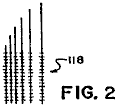
Fig.2 is a close-up view in general form of an electrical charge pick-up element which can be used in the generator illustrated in Fig.1.
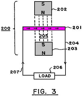
Fig.3 is a schematic view in generalised, representational form of a second embodiment of an electrical generator based on the principles and guidelines of the present invention.
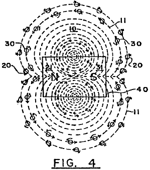
Fig.4 is a schematic view in generalised, representational form of the negative and positive particles exhibiting gyroscopic actions which emanate from a magnet to form an electromagnetic field.
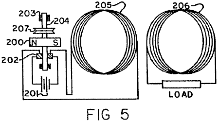
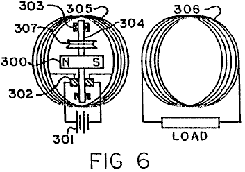
Fig.5 and Fig.6 are schematic views in generalised, representational form of third and fourth embodiments of a combined electrical generator and motor utilising a static, relatively large coil energised by a relatively low current driving a rotatable magnet, wherein in the embodiment of Fig.5 the rotatable magnet is positioned along side of the coil and in the embodiment of Fig.6 the rotatable magnet is positioned within the open core of the coil.
DETAILED DESCRIPTION OF-PREFERRED EMBODIMENTS:
Basic
Principles and Guidelines
In accordance with the principles of the present invention and as generally illustrated in Fig.3, an electromagnetic field 10 comprises flows of quanta or particles 20, 30 of electrical energy flowing from each of the poles 21, 31 of a magnet (or electromagnet) 40 to the other pole, following the "lines of force" 11 of the electromagnetic field. These particles 20, 30, believed to be travelling at the speed of light, are always coming out of one end 21, 31, respectively, of the magnet 40 and going into the other pole 31, 21, respectively, flowing from a relatively high energy source to a low energy source.
These particles 20, 30 are, it is believed, negative and positive charges and have a spin producing a gyroscopic motion and follow the mechanical laws of gyroscopic action.
The mass of each of the particles 20, 30 equals the energy of the particle divided by the speed of light squared. The peripheral speed of the gyroscopic spin of the particles is believed to be the speed of light.
For purposes of illustration only and as a matter of nomenclature, the positive charge particle 20 is going in one direction ('-'N" to "S") with a clockwise spin, and the negative charge particle 30 is going in the opposite direction with a counter-clockwise spin. Of course, if a particle such as 20 or 30 is flipped around one-hundred-and-eighty degrees, it becomes the opposite charge or type of particle.
The electromagnetic field 10 is thus the orderly flow of the positive and negative charges 20, 30 moving at the speed of light from the north and south poles 21, 31, to the south and north poles 31, 21, respectively, and follow the paths of what is termed in the art as the "lines of force" 11 of the electromagnetic field 10.
As is known from the laws of gyroscopes, a gyroscopic particle or body moves at right angles to the direction of an applied force. Therefore, when a force is applied to the electrical energy particles 20, 30, they will move at right angles to that force.
It should also be noted from known gyroscopic laws that the electrical energy particles 20, 30, when they move with their gyroscopic axis straight into an object, tend to knock that object straight, but, if that object hits the particles at an angle to the axis other than at zero or one-hundred-and-eighty degrees, the particles are moved off at an angle from the straight.
Additionally, it is noted that a magnetic field caused by a current flowing through a wire comes from negative and positive particles, such as 20, 30, with a net flow of such particles going in the same direction but with opposite spin.
In the system and method of the present invention, the foregoing principles serve as guidelines in the present invention.
Reference is further had to pages DD23 through DD27 of the Disclosure Document and to page 8, line 26 through page 11, line 23 of the prior application Serial number 25,907 and its Figures 7 - 10.
From the foregoing disclosures, many different devices, structures, and methods are possible to embody the principles and guidelines of the system of the present invention, which will in general utilise a material or substance or structure to place a force at the proper angle to the gyroscopic particles 20, 30 wherein the particles 20, 30 follow a path or paths which do not cancel one another out, thereby producing electrical current at appropriate outputs for further use or for increasing available potential electrical energy for ultimate use.
-First Embodiment (Fig.1)
One possible, exemplary embodiment using the principles of the system of the present invention is schematically shown in the generalised illustration of Fig.1.
As illustrated in Fig.1, there is provided an electrical current generator 100 comprising an outer keeper housing 115 and an inner, pressure containing, closed housing 116 supported therein by insulating supports 105. A vacuum exists in the area 106 between the two housings 115, 116, which vacuum is regulated and induced by means of the vacuum line 104 with its gauge 107 and its control valve 108. The outer housing 115 acts as a keeper for magnetic fields of force, and can be made for example of soft iron, while the vacuum in area 106 prevents the leakage or discharge of static electrical charges which might build up on the exterior of the inner housing 116.
A gas or gas-liquid mixture 117 which may also include solid particles such as for example lead or brass filings, is included within the inner housing 116 surrounding a series of aligned magnets 120 carried by insulating braces or supports 121 and producing a high, combined electromagnetic field. The magnets 120, which can for example be cryogenic magnets, have their "north" and "south" poles aligned (as illustrated by the "Ns" and "Ss") so that their magnetic fields reinforce one another.
The level of the gas or gas-liquid mixture 117 in the housing 116 is regulated by means of the line 122 with its gauge 123 and control valve 124. Electric current output wires 119 are provided and extend down to electrically connect with a wire pick-up system 118 (shown in close-up in Fig.2), which can be for example in the form of very small wires forming a closely spaced network or mesh or of a porous conducting metal body or sheet, located in and extended throughout the fluid 117 in the housing 116.
It is noted that a thimbleful of gas contains a fantastically large number of extremely tiny bodies which are in continuous, random motion moving at extremely high speeds. Hence, the fluid 117 continuously applies a force to the gyroscopic particles (analogous to particles 20, 30 of Fig.3) moving at the speed of light ' in the high electromagnetic field (produced by the magnets 120) as they continuously collide with each other, which results in the fluid 117 becoming electrically charged. The charged fluid 117 discharges its electrical charge to the pick-up wire network 118 positioned in the fluid, and the electric current so produced and generated is taken off for use via the electrical output wires 119.
As an alternative to having internally contained magnets 120, the electromagnetic field needed in the fluid 117 could be produced by a source located outside of the confines of the fluid 117 as long as a significant field was produced within the fluid 117.
-Second Embodiment (Fig.3)
A further exemplary, generalised embodiment utilising the principles of the system of the present invention is shown in schematic form in Fig.3.
The electrical current generator 200 of Fig.3 comprises an extended member 201 of a special material having its atoms especially aligned to produce electric current when positioned in an electromagnetic field but which does not on its own exhibit any substantial magnetic field outside of its boundary surfaces but substantially contains the field within itself. This is in contrast to "magnetic" materials which likewise have atom alignment but which also exhibit or produce a substantial magnetic field in the area surrounding it.
The generator 200 further comprises for example two magnets 202, 203, with their north and south poles facing each other, with the member 201 positioned between them, and with the three elements 201-203 held static with respect to each other. Because of the special nature of the material of the member 201 and its special atom alignment, it will produce a direct current through output line 204 as a result of the gyroscopic actions of the particles of the electromagnetic field 205 produced by the facing magnets 202, 203, on the especially aligned atoms in member 201, which phenomenon occurs even when and even though the member 201 is completely static with respect to the magnets 212, 203.
However, it may be desirable in some applications to allow or produce some relative movement between the generator elements 201-203. The output line 204 extends to an appropriate "load" 206 for using the electrical current generated by the generator 200. A return line 207 completes the circuit back to the member 201.
Based on experiments to date, it is believed that brass and lead are materials which can have their atoms especially aligned to interact with the gyroscopic particles (analogous to particles 20, 30) flowing between the magnets 202, 203 and will substantially contain within their surface boundaries the magnetic field produced by the aligned atoms or molecules.
With respect to producing the proper material with atom alignment for the member 201, it is noted that most materials seem to align their atoms in random directions when formed by conventional methods of production. However, it can be observed that certain materials can be made magnetic by putting the material in an electromagnetic field while cooling from a temperature of around a thousand degrees Centigrade. The magnetism is the result of atom alignment of the material in a given direction (see pages DD19 through DD21 of the Disclosure Document). All materials are affected so as to align parallel or across lines of force when in a powerful electromagnetic-field. Accordingly, if a material while being formed is cooled in an extremely powerful electromagnetic field, the atoms of the material will take a particular alignment. The atom alignment direction could be varied depending on whether the electromagnetic field was aligned with the material or at a ninety degree angle to the material. This would result in the atoms of a material having their particular electromagnetic spin direction primarily along the same axis.
However, merely having atom alignment is not sufficient. Additionally the material for the invention should be such that it exhibits very little if any magnetic field in the area surrounding it. Thus it should be noted that the exterior electromagnetic field that occurs from the atom alignment of the conventional magnet is not duplicated in the material of the invention, because the electromagnetic energy resulting from atom alignment in the material of the invention will be primarily contained within the boundaries of the material It is believed that lead, made superconductive by immersion in a bath of for example liquid helium, is such a special material and could for example serve as the material for member 201.
This then results in having a material which would place a force at the proper angle on the gyroscopic type particles moving in the electromagnetic field so as to cause an EMF to be produced even when the material was sitting still. (See also first paragraph of page DD23 and paragraphs four, A through E, of page DDl9 of the Disclosure Document).
It is believed that high, contained pressures, as well as other methods, can also probably produce atom alignment as the atoms of a conductor or any material will react to sufficient external force. (See first paragraph of page DD35 of the Disclosure Document). This possibility is also indicated by the fact that hard knocks or impacts will demagnetise a magnet.
The proper procedure of material production in achieving atom alignment with internally contained fields of force will cause the controlled release of electrical energy in electromagnetic fields of force when the material of the invention is placed in the lines of force of the electromagnetic field.
-Third and Fourth Embodiments (Fig.5 and Fig.6)
A. Related Principles
1. Numerous scientific tests and experiments made by the inventor indicate that the magnetic field resulting from an electrical current flowing through a conductor is the result of atom alignment within that conductor at an extremely high speed with an ability to reverse atom alignment just as rapidly without the magnetic hysteresis associated with conventional materials considered "magnetic." Prior to this time it has been believed and taught by the scientific community that the magnetic field associated with an electric current carrying conductor was the result of the electric current itself and not of the conductor material, for example copper, which was considered to be "nonmagnetic." Even the inventor was influenced and mislead by these teachings and attempted to mechanically explain and justify the prior teachings, as is seen on page DD-27 of the Disclosure Document which is an important part of this patent application.
However, as taught in the present invention, what mechanically happens is that the gyroscopic particles making up the electric current moving in a conductor interact with the electromagnetic makeup of the atoms of the conductor, causing them to align extremely rapidly, thereby then releasing some of their electromagnetic make-up in the form of a magnetic field exactly as explained in great detail for conventional magnetic materials in the Disclosure Document.
This is easily proven and understood by taking for example, a size 14-gauge conductor one foot long, winding it into a coil and connecting the coil to a meter and a 1.5 volt battery. The total current registered on the meter will be 1.5 amps and the strength of the magnetic field created from the short conductor will be extremely small. Next, the same type of test is run again but with the length of the conductor increased to for example two thousand feet, but still in a coil. The total current registered on the meter will now be considerably less, but the strength of the magnetic field given off from the conductor will now be extremely large!
This shows that the magnetic field is not from the electric current flow, but is the result of the interactions of the gyroscopic particles which make up the electric current interacting with the atoms of the conductor! This causes the gyroscopic particles of the electric current not to be able to make the circuit back to the battery so quickly, and therefore the meter shows less current used.
The magnetic field is the result of the atom alignment of the conductor. The more atoms in a conductor (up to a point), the stronger the magnetic field produced from a given amount of electric current input. Again, this is proven by changing the diameter of the conducting wires, and, with the lengths being the same, the strongest magnetic field will result from the conductor with the largest diameter. The reason for this is that there are more conducting atoms to interact with the gyroscopic particles of the electric current moving through the conductor, which results in a greater number of conducting atoms being aligned, thereby then releasing some of their electromagnetic make-up, exactly as has been explained in great detail in the Disclosure Document as being possible for all matter.
If the magnetic field produced was strictly based on the amount of current going through a conductor, as taught in the prior art, then the strongest magnetic field would result when current went through a large diameter and short length conductor, because the current flow through the entire circuit is greatest at that time. However, experiments prove that the shorter a conductor is made, the greater the current flow through the entire circuit and the less strength of the magnetic field surrounding that conductor. The longer that same conductor is made (up to a point), the greater the magnetic field surrounding the total mass of the conductor and the less current that makes the complete circuit of the entire system. Reason: more atoms!
2. Numerous scientific tests and experiments made by the inventor also indicate that the magnetic field created when an electric current moves in a conductor does not use up measurable energy when performing obvious or non-obvious work, force or power. This is true no matter how strong or how immense the power of the motor or electromagnets is.
Reason: the magnetic field coming from the conductor is the result of extremely quick atom alignment within that conductor. Therefore the energy in the magnetic field is the energy that makes up the atoms of the conductor! This energy is literally Einstein's equation of E=MC2, and therefore the energy is believed to be moving at the speed of light.
This energy use cannot be measured by today's measuring instruments. This has been explained in great detail in the
Disclosure Document and is believed to be true of all matter!
3. The same is true for the electric current that comes from a conventional battery. The electromagnetic energy coming from the battery is the energy that makes up the atoms of the material of the battery! Again this energy use is not measurable by today's measuring instruments. Electric meters of all types are simply mechanical devices which measure the amount of electric current that comes into that instrument. They do not measure the amount of mass that has been converted into electromagnetic energy.
Present teachings in science state that the electric energy flowing from a battery is used up in the device operated by that flow of electric current. This is not true at all! The electromagnetic energy released from the atom make-up of a battery has a relatively infinite capacity to do obvious work, force, or power.
This is easily proven even with a small motor and a 1.5 volt battery. With a battery connected to motor to operate it and with a meter to take readings, the motor is then physically stopped from turning by physically holding or restraining the shaft. At that moment the motor is performing no obvious work, force or power, but the meter will register a greater flow of current. The magnets of the motor can be taken out and the reading will still be the same. If the electric current was being used to operate the motor, the meter would register more current when the motor was running.
The electric current not only will operate the motor but, once it flows through the complete circuit back to the battery, it also does additional work based on Faraday's Laws of Electrolysis within the battery itself. What has happened is that the electromagnetic energy released from the atoms of the material of the battery once they have completed the circuit, then take a "short cut" and move large pieces of the mass of one material of the battery over to the other material of the battery. The inventor has stated and shown throughout the Disclosure Document that the effect of gravity was the non-obvious effect of electromagnetic energy. Once the materials of the battery have combined, the extreme desire for the two materials to merge is physically reduced. These materials will attempt this merger anyway possible and, if the electric current initially released from a battery is not allowed by mechanical means to complete the circuit back within itself, the electromagnetic energy then in the mechanical means will perpetually (in a relative, theoretical sense) perform obvious work, force or power. The reason: the force which initiated this flow of current (electromagnetic make-up of atoms of material) is constant, similar to hydraulic pressure, with the noticeable exception that it is moving it is believed at the speed of light and will interact with the electromagnetic make-up of the atoms of other materials, causing them to release some of their electromagnetic make-up in the form of a magnetic field. This then multiples the capacity for doing obvious or non-obvious work, force or power, which can then react with another conducting coil or with the electromagnetic energy within the magnetic field of a conventional magnet and multiply this effect even further, and on and on and on for a relatively unlimited source of energy.
The same is true in not letting the current get back to a conventional generator. If a mechanical means is set up so that the electric current is "trapped," without completing a circuit, the gyroscopic particles of the current have a capacity for continuous work without increasing the power input into the generator system. However, if the circuit is complete and the electric current moving in the system does absolutely no obvious work, power or force, the gyroscopic particles making up the current on getting back to the generator will then increase the need for more power input into the system. Reason: the opposing effect of magnetic fields as defined in Lentz’s Law. This law is simply an observation of this effect, which before now has never been fully understood.
4. Numerous scientific tests and experiments made by the inventor also indicate that there is a correlation between the electromagnetic spin orientation of the atoms of non-conductors, semi-conductors, and conductors, and the varying results achieved with an electric current in attempting to move through these materials, or when moving these materials through a magnetic field attempting to induce electric current. The property of resistance to electric current movement is generally speaking the same type factor already explained above for electric current producing a magnetic field when moving in a conductor.
The gyroscopic particles in a moving electric current interact with the atoms of the material through which the current is moving. Each atom can efficiently only interact with sun exact maximum amount of electric current, and, if exceeded, there is an interruption of orderly movement. Then the angle of release of the gyroscopic particles from the atoms are such that the electromagnetic release from those atoms are in the form of heat, exactly as explained in great detail in the Disclosure Document. This effect is easily observed by the fact that resistance decreases relative to an increase of the cross-section of the material. Reason: simply, more atoms within that given area, and, for a fixed input of electric current, there are more atoms to receive and interact efficiently with the gyroparticles making up the electric current.
Again the same is true for resistors designed for deliberately producing heat. Such resistors are not materials which are considered good conductors of electric current. It is stated and shown in great detail in the Disclosure Document that the electromagnetic spin orientation of the atoms of a non-conductor are different from that of conductor atoms, and therefore different results will occur from the same inputs of electromagnetic energy.
This is easily seen by the fact that, in a resistor, for a given amount of electric current input, the heat release increases as the diameter increases. What that means is that the property of resistance has decreased. On a conductor it is just the opposite. If the diameter is increased the resistance is decreased, but so is heat release. Again, this is an indication that the gyroparticles in the electric current movement interact with each atom of the material. This same effect shows up again in conventional electrical induction from a conductor interacting with a magnetic field. Experiments by the inventor have indicated that the property of conventional induction is the result of the same property of resistance.
If one increases the diameter of a conductor, lengths staying the same, one decreases the amount of electric current produced relative to the total number of atoms within the conductors under consideration. Or, if one takes a given number of wires of the same diameter and length, and moves a magnet across them, the current produced will be considerably less, than if one takes the same diameter wire, but only one wire, and increases its length considerably and then forms it into a coil forming the same number of wires on any one side and then moves the same magnet across only one side of that coil, the electric current generated will then be considerably greater. Reason: the property of resistance. This is the mechanical effect within the gyroscopic electromagnetic make-up and orientation of the atoms of all materials which have the mechanical ability to perform a given task efficiently up to a point concerning input of additional electromagnetic energy and then mechanically causes varying results once this threshold is exceeded.
This and all the other thoughts and innovations in this and the previous disclosures of the previous applications and the Disclosure Document previously put forth show that there are many different mechanical ways to release a relatively unlimited source of energy from electromagnetic energy which makes up all matter and which results from this invention.
B. Working
Prototypes
Fig.5 and Fig.6 illustrate rough, working prototypes of this aspect of the invention. These embodiments are only relatively inefficient prototypes built by hand for the purpose of demonstrating the invention. It should be self-evident that the prototypes, by various mechanical means and designs, can easily be made extremely efficient and the illustrated embodiments are being presented only for general, representational purposes.
As is illustrated in Fig.5, there is provided a combined electrical current generator and an electromagnetic motor comprising a rotatably mounted, permanent magnet 200, a battery 201, brushes and commutator 202, bearings 203 and power, mounting shaft 204, and a first, primary, magnetic producing coil 205 and a second, secondary electric producing coil 206. The two coils 205, 206 are juxtaposed together in parallel disposition with concurrent core centre-lines, with the magnet 200 positioned alongside of coil 205 at or near its core centre-line with the rotational axis of the shaft 204 positioned orthogonally to the centre-line.
In the prototypes a very small battery 201, for example, size "N", of 1.5 volts is used. When the circuit is completed, the battery 201 converts an immeasurable amount of its mass into electrical current (gyroscopic particles moving at the speed of light) which goes out through the communicator and brushes 202, and then enters magnetic producing conductor coil 205 made, for example, from insulated 14-gauge or 15-gauge copper wire, with the total weight of the coil 205 being for example seventy to ninety pounds. This causes the atoms of coil 205 to align extremely fast then releasing some of their electromagnetic make-up (gyroscopic particles) in the form of a magnetic field. This field then interacts with the gyroscopic particles making up the magnetic field coming from the atoms of the material of the permanent magnet 200.
This causes magnet 200 to attempt to align its magnetic field movement with the magnetic field movement coming from the atoms of coil 205, resulting in rotation of magnet 200 and the shaft 204 to which it is attached. This then changes the position of the commutator and brushes 202 relative to each other's initial positions, which then causes the electric current coming from battery 201 to be going in the opposite direction into coil 205, causing the atoms of coil 205 to extremely quickly reverse their alignment and the polarity of their magnetic field which they are emitting. The reversed field then interacts again with the magnetic field of permanent magnet 200, causing it to further rotate.
This process is then continuously repeated, producing continuous rotation of the shaft 204 which can be used as a source of motive power in many different ways. A power belt wheel 207 for example using a continuous "V" belt is illustrated as a general representation of this motive power source for producing useful, obvious work. In a prototype test run with a small 1.5 volt, type "N" battery, the shaft 204 and the magnet 200 - rotated at a high speed for approximately twelve hours before running down. By improving the particular design features of the prototype and by using longer lasting batteries, the rotation time of the shaft 204 can be greatly increased to a theoretical point approaching "perpetual" for all practical purposes. At the same time the alternating magnetic field produced by the coil 205 induces into coil 206 electrical induction, which then causes coil 206 to produce an alternating current across its "load," which current can be made to exceed the conventional output of the battery 201. The battery source 201 can be replaced when needed.
It is very important to understand that, the longer the length of the conducting wire in coil 205, the stronger will be the magnetic field produced and the less electric current that will complete the circuit and get back into the battery and destroy the mechanical source of the electrical current. This effect can be increased further by increasing the diameter of the conducting wire in coil 205 and then greatly increasing its length still further in the coil.
Reason: The gyroscopic particles making up the electric current interact with the atoms of coil 205. The more atoms in coil 205, relative to it’s length, the longer it takes the gyroparticles of the electric current to influence them and exit from the other end of the coil. It is then easily seen that if the direction of the current flowing into coil 205 is then reversed, this then further increases the lag time. Reason: The gyroscopic particles have inertia and are believed to be moving at the speed of light and they are interacting with the gyroscopic particles making up the atoms of the conducting coil 205. These atoms also have inertia, and when the direction of current in coil 205 is reversed, the incoming current then collides with the current already in coil 205 going in the opposite direction.
This causes a brief hesitation during the time the current already in the coil is being forced to reverse its direction, thereby then reversing the direction of the atoms within coil 205 which have already been influenced to become aligned. This causes a constant force throughout the circuit, but does not allow very much current to get back into the battery 201 to destroy the mechanical means which initiated the release of electric current in the first place.
Therefore, it should be further understood that, the faster the current direction reverses into the coil 205, the more efficiently the matter of battery 201 is converted into 2 pure electrical energy (E=MC2), without destruction of the mechanical situation that initiates the electrical current release.
It is also important to understand that, the stronger the magnetic field coming from the mass of magnet 200, the greater will be its rotational speed. Additionally, the greater the magnetic field coming from the mass of coil 205, the greater will be the rotational speed of magnet 200, and, up to a point, the greater the electric current input from battery 201, the greater the rotational speed of magnet 200.
Reason: the greater the electric current flow into coil 205, the greater will be the percentage of the atoms making up coil 205 that are aligned. This probably has the same relationship as does achieving atom alignment in conventional magnetic materials. Once complete atom alignment is reached in coil 205, no amount of current will cause those atoms to increase the strength of the magnetic field emitting from those atoms.
Therefore, it should be clear that, for a given input of electric current from battery 201, the most efficient design is one in which the most atoms of coil 205 are influenced to atom alignment by that given electric current, which means increasing the diameter and the length of the conducting wire of coil 205 to the point that the strength of the magnetic field produced is sufficient to cause rotation of the magnet 200 to a speed that allows none or at least very little of the electric current which initially comes from the battery 201 to complete the circuit and get back into battery 201 and destroy or reduce the mechanical effect which induced the conversion of the matter of battery 201 in electric current in the first place. Again this desired effect can be increased by increasing the strength of the magnetic field given off by the atoms of the permanent magnet 200.
In the second prototype embodiment of Fig.6, the structure and operation of the prototype is substantially identical to that of Fig.5 with the major exception being that the magnet 300/shaft 304 elements (and related sub-elements 302, 303 and 307) are positioned inside of and within the core of the primary coil 305, as compared to the placement of the magnet 200/shaft 204 elements next to and along side of the coil 205 of Fig.5. Therefore, for brevity, a detailed description of the elements of Fig.6 will not be repeated, but it is noted that the corresponding and analogous elements and sub-elements are similarly numbered in Fig.5 and Fig.6.
It is also important to again stress the fact that the prototype designs shown are presented simply to prove the correctness of the invention, and it should be clear that the invention can be made extremely more efficient by utilising all of the magnetic field produced by coil 205 and designing the magnet 200 of a shape and strength that efficiently interacts with the majority of the magnetic fields from coil 205. The illustrated prototypes is relatively highly inefficient in this regard, but even so, the results of the invention itself greatly exceed the prior art as to use of electric current from whatever source and interaction with an electric motor or whatever work was conventionally performed.
The applicant feels it is very important to again stress, in building many varying designs of this invention, consideration must be given to the fact that the Energy in the field of force of any type magnet is the Energy that makes up the Atoms of the material from which it comes! This Energy is a real Entity with, it is believed, a gyroscopic action. It is literally Einstein's Equation of E=MC2 and it is believed that this Energy moves at the speed of light and makes up all Matter. And that this Energy has a constant pressure effect back to the Atoms of the material from which it came, similar to hydraulic pressure. This effect is additionally more fully understood by stating the following results obtained from experimentation by the applicant in the process of this invention.
a) When the system is initially attached to a 1.5 volt size N Battery 201 or 301 and the magnet 200 or 300 and related rotation entities are placed close to or in the centre of coil 205 or 305, the following results are observed:
If the electric current produced in coil 206 (306) is then fed back into coil 205 (305) in accordance with proper polarity, the rotation speed of magnet 200 or 300 will then accelerate. If fed back into coil 205 (305) in wrong polarity, the rotation speed of magnet 200 (300) will slow down.
This proves that the total force from coil 205 (305) interacting with the magnet 200 (300) is greater when the electrical energy from coil 206(306) is fed back into coil 205 (305), then when only the initial electric energy from battery 201 (301) is fed into coil 205 (305)! When two or three batteries are electrically connected together in series, so as to create for example three or four and a half volts of electrical input, this effect is multiplied. Remember, up to a point, the greater the electrical input, the greater the percentage of atom alignment within coil 205 (305).
This further proves that the electric current produced in coil 206 (306) is a result of the gyroscopic particles of Energy released from the magnetic fields which came from the Electromagnetic make-up of the atoms of coil 205 (305), and is not part of the initial Electrical Energy released from the atoms making up the materials of battery 201 (301)! The coil 206 (306) can be taken out of the system, or its electrical current fed away from the system, and the rotational speed of the magnet 200 (300) will not observably change. However, the rotational speed of magnet 200 (300) will noticeably change when the electric current from coil 206 (306) is fed back into coil 205 (305)!
Now a different result:
b) When the electric current from battery 201 (301) becomes weaker to the point that the magnetic field coming from coil 205 (305) has weakened and shrunk allowing the magnetic field of the rotating magnet 200 (300) to expand and then noticeably induce electric current into coil 206 (306) and into coil 205 (305), then reverse results are observed. When the magnetic field from the coil 205 (305) is large, then the magnetic field from magnet 200 (300) is retained! If coil 206 (306) is then short circuited, the rotation of magnet 200 (300) will noticeably slow down.
If electric current from coil 206 (306) is fed back into coil 205 (305) in wrong polarity, the rotation of the magnet 200 (300) will stop. If fed back into coil 205 (305) in correct polarity, the rotation of the magnet 200 (300) will slow down. At that point, the rotation of the magnet 200 (300) will not accelerate, no matter how connected!
These results show that, at this time, the magnetic field from magnet 200 (300) noticeably induces a current in coils 206 (306) and 205 (305) which opposes the rotation of the magnet 200 (300). This effect has already been mechanically explained, and it has been shown that Lenz’s Law was simply an observation of that mechanical explanation. These results further demonstrate that the expanding and collapsing magnetic fields from coil 205 (305) and 206 (306) do not noticeably effect each other detrimentally.
Because the resulting magnetic fields from all the coils are the results of fluctuating atom alignment within the coils! Remember, the gyroscopic energy particles making up the magnetic fields have a hydraulic pressure effect back to the atoms from which they came. Also remember that the atoms making up the material of the permanent magnet 200 (300) are stationary as to atom alignment direction! Therefore, the pressure effect resulting from an opposing field which the magnet 200 (300) induced, is immediate. As is Hydraulic Pressure.
However, the magnetic field emitted from the atoms of coil 205 (305) relative to induction into the atoms of coil 206 (306) are fluctuating and out of step, so to speak, and therefore, in harmony with each other. The pressure effect from the induction of coil 205 (305) into coil 206 (306) is an action and reaction effect which reinforces the flipping action of the atoms of coil 205 (305) and back into the atoms of coil 206 (306).
This action is again seen when the invention is hooked into one-hundred-fifteen volt alternating current, and battery 201 (301) is not used. The magnet 200 (300) will not rotate even though the magnetic field from coil 205 (305) is strong and is alternating. Reason: The fluctuating magnetic field is so fast, that the inertia mass of magnet 200 (300) can not get started in one direction before the magnetic field from coil 205 (306) has reversed, thereby, causing magnet 200 (300) to vibrate only microscopically at sixty cycles per second. And, if a sixty watt bulb is hooked into the system of coil 205 (306), it will only light dimly. And there is a lag time of two to three seconds before it lights even dimly.
If then coil 206 (306) is hooked to a meter, there is a reading of forty-nine volts, and if the meter is replaced by another sixty watt bulb it will light only extremely dimly. However, the sixty watt bulb hooked to coil 205 (305) will now become noticeably brighter! This again shows that the action and reaction results of the atoms of the coils are not noticeably detrimental to each other. Because of the lag time (out of step, so to speak), resulting in reinforcing the flipping atom alignment of the coils.
From this further explanation of the invention it is seen that desirable results may be obtained by the following:
For example, in Fig.6 the magnet 300 may be of a design and/or be located at a distance from the inside diameter of coil 305 and coil 306, whereby the majority of the magnetic field from the magnet 300 does not cut the conducting loops of coil 305 or 306. Yet the alternating magnetic field produced by coil 305 should efficiently have the majority of its gyroscopic particles interacting with the majority of the gyroscopic particles making up the magnetic field of the permanent magnet 300, but not directly reacting with the atoms making up coil 305, or magnet 300!
When the magnetic lines of force of the magnet 200 (300) cross at right angles with the conducting wires of coil 205 (305), 206 (306), a braking action is incurred. It should be noted that, as the inner diameter of coil 205 (305) increases, the percentage of time of braking effect decreases.
Along this same line of instruction, the commutator segments 202 (302) can be made of a large diameter and the area of brushes made small, whereby, when the brushes cross over the gaps in the commutator segments, there will be no short circuit at any time directly back to the battery 201 (301).
By combining the slip rings and brushes (the slip rings can be made of a small diameter) to the side or sides of the brushes and commutator segments 202 (302), then battery 201 (301) does not have to rotate with magnet 200 (300).
The 14-gauge and 15-gauge insulated copper wire weighing seventy and ninety pounds respectively (31.5 kilograms and 40.5 kilograms) used for the motor coil 205 (305) and the generator coil 206 (306), respectively, in the first hand-made prototypes of the embodiments of Fig.5 and Fig.6, for demonstration purposes only, come in standard buckets of varying weights from wholesale outlets.
It was then wound in coils as shown, and, as taught, the more conducting wire used, the better the results. The magnets 200 and 300 were each initially about a 2.5 inch (6.25 centimetre) cube and can be any size and strength desired.
In a further, rough, hand-built, demonstration, working prototype of the invention of the type illustrated in Fig.6, the primary or motor coil 305 was made of 5-gauge copper wire in a single, continuous wire, weighing approximately 4,100 pounds (1,845 kilograms) with a coil loop diameter of 4.5 feet (135 centimetres), while the secondary or generator coil 306 was made of 24-gauge copper wire in a single continuous wire weighing approximately 300 pounds (135 kilograms) with the same, approximate coil loop diameter of 4.5 feet (135 centimetres), with both coils 305, 306 coincidentally forming a cylinder of approximately 30 inches (75 centimetres) in length. The coils 305, 306 were built around a cylindrical, fiberglass core body of approximately 200 pounds (90 kilograms) having a vertical, longitudinal centre-line axis.
The rotating magnet 300 was made up of six, separate, parallel cylindrical magnetic columns spaced and disposed about the periphery of a hollow cylindrical fiberglass surface of approximately twenty inch (fifty centimetres) in diameter. Each column was 30 inches 75 cm.) long and was composed of a stack of 70, individual ceramic ring magnets in disc form as made by Jobmaster Magnets of Randallstown, Maryland, 21133, U.S.A. Each disc had a thickness of seven-sixteenths of an inch (1.09375 centimetres), an inner diameter of 1 inch (2.5 cm.) and an outer diameter of 4 inches (10 cm.). The discs were stacked and secured together in 4 inch (10 cm.) diameter fiberglass tubes longitudinally mounted on the inner surface of the twenty inch (fifty cm.) diameter fiberglass cylinder.
The composite magnet 300 had a total weight of approximately 400 pounds (180 kilograms) and a total length of 30 inches (75 cm.) and an approximate diameter of 20 inches (50 cm.).
The magnet 300 was mounted for rotation on a horizontal shaft 304 extending across the hollow core of the coils 305, 306 crossing through the centre point of the longitudinal centre-line of the cylinder and orthogonally to the longitudinal centre-line of the magnet 300 for rotation within the open centre area of the cylindrically disposed coils 305, 306 with the longitudinal centre-lines of the coils being vertically disposed.
With a D.C. battery source 301 of two 12 volt lantern batteries and seventeen 6 volt lantern batteries all in series (totalling 126 volts), a measured voltage of 126 volts and a measured current of 99 milliamps in the primary coil 305 were noted. Concurrently a voltage reading of 640 volts and an amperage measurement in excess of 20 milliamps were noted in the secondary or generating coil 306, with the magnet 300 rotating at a speed of 120 revolutions per minute (rpm). Thus the system was outputting and producing in the generating coil 306 usable electrical energy in excess of 102% of that being inputted in the motor coil 305! This excess useful electrical energy, of course, is in addition to the further useful mechanical energy available at the exemplary drive take-off 307 on the rotating shaft 304, on which the 400 pound, 30 inch long magnet 300 was rotating at 120 rpm!
Thus the invention, by utilising the energy of the gyroscopic particles in the magnetic field, produces a greater energy output than the energy input into the system, thus producing results beyond presently accepted scientific teachings of the world.
This prototype achieves exactly what has already been described in great detail in applicant's prior patent applications. There was simply used in this prototype a stronger magnet and a larger diameter conducting wire of great length, that has a considerably greater number of atoms aligned when current is put into the system, and used a greater number of atoms in the generator coil of fine diameter conducting wire.
While the results of the energy released from this particular prototype is highly impressive to others, the applicant still has only scratched the surface of the energy that can be released using the principles of the present invention.
Again, as has already been stressed, the most efficient design, is one in which the least amount of input of current causes the greatest amount of atom alignment.
These data do not constitute any departure from applicant's previous work, but is only to further document that which has already been stressed in the prior patent applications.
Varying the D.C. voltage for the battery source 301 shows that obvious efficiency will continue to rise as the voltage input goes up! Also, the leverage factor advantage of the invention, combined with the inertia of the 400 pound magnet 300 rotating at 120 rpm (even while causing the electrical generator to put out over 100% of energy input) proves the invention to be greatly over 100% efficient even at this slow rpm.
It is contemplated that the next prototype will use super-conducting type material for the coil 305 with a magnet 300 having a magnetic field strength comparable to that of crycogenic-type magnet relative to percentage of atom alignment or size. This will result in the size of the device being much smaller and yet with the available work output being much greater than the prototype just described. Reason: The most efficient type design is one whereby the least amount of current input into the motor coil produces the greatest atom alignment of said motor coil and having rotatable magnet also comparable in strength, relative to size.
The invention can be made without using the coil 206 (306) and producing just useful mechanical energy.
Coil 206 (306) can be merged or wound with coil 205 (305).
The magnet 200 (300) can be an electromagnet, a permanent magnet, a cryogenic magnet or any magnet.
The design of magnet 200 (300) can create a strong but retained magnetic field.
The design of coil 205 (305) can be used to further retain the magnetic field of magnet 200 (300).
Alternating current (A.C.) can be used in place of the direct current (D.C.) battery 201 (301), if the magnet 200 (300) is designed accordingly.
The coils 205 (305) and 206 (306) may be made up of several coils rather than a single coil.
The magnet 200 (300) may be made up of several individual magnets rather than from just a single magnet.
From the foregoing it should be understood that, unlike the teachings of the prior art, the following is desired in the design of the coil 205/305 under the principles of the present invention:
a) Current initially flowing into and through the coil should be small compared to the energy output of the system;
b) A relatively large diameter wire or its equivalent is used for the coil;
c) A relatively large number of coil loops or coils is used;
d) A relative long, continuous length of coil wire or its equivalent is used; and
e) The greatest magnetism for a given mass of the magnet 200/300 is desired but may be designed so that the magnetic lines of force will not cut the coils at a right angle.
The present invention applies to any mechanical device which is operated by electrical energy. In accordance with the principles of the present invention, the mechanical device should be designed wherein the electric current as much as is feasible cannot get back to its source, but the circuit is completed whereby the "pressure force" is constant throughout the system.
What has been invented, built and disclosed is an invention of immense importance to the well-being of the entire world. There will be many devices built from what has been shown and taught. It should now be known that all matter is made up of electromagnetic energy and that there are many mechanical ways to release this energy, as has been stated throughout the five prior, related patent applications hereof and the Disclosure Document. All of these future developments will be as a result of the present invention which - releases energy above and beyond conventional energy release mechanisms, prior to this invention.
Some of the basic approaches of the invention are outlined below:
l. Any device which utilises a means by which the electric current (electromagnetic energy) is retained within a member or members outside of the source of said original electric current and then, as a result thereof, is capable of producing a continuous electromagnetic motion or current if so desired beyond present scientific teachings.
2. Any device which releases the electromagnetic energy make up of matter to such an impressive degree as does this invention that it defies several of the present accepted laws of physics and electrical engineering as of this time.
3. That the energy release is noticeably higher and in some cases more controllable than the conventional means of energy release of this time.
Because many varying and different embodiments may be made within the scope of the inventive concept taught here, and because many modifications may be made in the embodiments detailed here in accordance with the descriptive requirements of the law, it is to be understood that the details given above are to be interpreted as illustrative and not in any limiting sense.
CHARLES FLYNN: MAGNETIC FRAME
Patent US 6,246,561 12th June 2001 Inventor: Charles J. Flynn
METHODS FOR CONTROLLING THE PATH OF MAGNETIC FLUX
FROM A
PERMANENT MAGNET AND DEVICES INCORPORATING THE SAME
This patent covers a device which is claimed to have a greater output power than the input power required to run it.
ABSTRACT
A permanent magnet device includes a permanent magnet having north and south pole faces with a first pole piece positioned adjacent one pole face thereof and a second pole piece positioned adjacent the other pole face thereof so as to create at least two potential magnetic flux paths. A first control coil is positioned along one flux path and a second control coil is positioned along the other flux path, each coil being connected to a control circuit for controlling the energisation thereof. The control coils may be energised in a variety of ways to achieved desirable motive and static devices, including linear reciprocating devices, linear motion devices, rotary motion devices and power conversion.
DESCRIPTION
FIELD OF THE INVENTION
This invention relates generally to permanent magnet devices and more particularly, to a permanent magnet control component in which the flow of flux from a permanent magnet is controlled between two or more flux paths by utilising timed delivery of electrical signals through one or more coils placed along at least one of the flux paths. Such permanent magnet control components may take on a variety of configurations facilitating use of such components in a variety of applications including applications involving the production of reciprocating, linear, and rotary motion and power conversion. Several novel permanent magnet rotary motion devices of motor constructions which operate by controlling the path of magnetic flux from one or more permanent magnets are described, such permanent magnet rotary motor constructions having increased efficiency and more desirable torque characteristics as compared to many currently used motors.
BACKGROUND OF THE INVENTION
Magnetic force of attraction is commonly used in a variety of types of permanent magnet devices including both linear and rotary motors. In the field of such permanent magnet devices there is a continuous pursuit of increased efficiency and reduced complexity.
Accordingly, an object of the present invention is to provide a permanent magnet control component in which the path of a given level of permanent magnet flux can be controlled by a lesser level of electromagnetic flux.
Another object of the present invention is to provide a permanent magnet control component in which substantially all of the flux from a permanent magnet can be switched between at least two different flux paths of the permanent magnet control component so as to enable useful work in the form of linear, reciprocating, and rotary motion.
Still another object of the present invention is to provide permanent magnet control components and motor constructions in which flux path control is provided by energising an 10 electromagnet to oppose the magnetic flux of one or more permanent magnets.
Another object of the present invention is to provide permanent magnet control components and motor constructions in which flux path control is provided by energising an electromagnet to aid the magnetic flux of one or more permanent magnets.
Yet another object of the present invention is to provide permanent magnet motor 15 constructions with improved operating characteristics.
SUMMARY OF
THE INVENTION
These and other objects of the invention are attained by an apparatus which, in one aspect, is a permanent magnet device, comprising a permanent magnet having north and south pole faces, a first pole piece, a second pole piece, a first control coil, a second control coil, and circuit means, the first pole piece positioned adjacent the north pole face of the permanent magnet and including a first path portion, a second path portion and a third portion, the first path portion extending beyond a perimeter of the north pole face and the second path portion extending beyond the perimeter of the north pole face to define first and second flux paths for magnetic flux emanating from the north pole face of the permanent magnet, the first path portion of the first pole piece connected to the second path portion of the first pole piece by the third portion which extends across the north pole face of the permanent magnet, the second pole piece positioned adjacent the south pole face and including a first path portion and a second path portion, the first path portion extending beyond a perimeter of the south pole face and substantially aligned with the first path portion of the first pole piece, the second path portion extending beyond the perimeter of the south pole face and substantially aligned with the second path portion of the first pole piece, the first control coil positioned around the first path portion of the first pole piece, the second control coil positioned around the second path portion of the first pole piece, the circuit means connected to each of the first control coil and the second control coil to alternately energise the first coil and the second coil in a timed sequential manner.
Another aspect of the present invention provides a method for controlling the path of magnetic flux from a permanent magnet which involves placing a first pole piece adjacent a first pole face of the permanent magnet so as to have at least first and second path portions extending beyond a perimeter of the first pole face. A second pole piece is placed adjacent a second pole face of the permanent magnet so as to include at least one portion which substantially aligns with the first and second path portions of the first pole piece. A first control coil is placed along and around the first path portion of the first pole piece and a second control coil is placed along and around the second path portion of the first pole piece. The first control coil is repeatedly energised in a permanent magnet magnetic flux opposing manner so as to prevent magnetic flux of the permanent magnet from traversing the first path portion of the first pole piece, and the second control coil is repeatedly energised in a permanent magnet magnetic flux opposing manner so as to prevent magnetic flux of the permanent magnet from traversing the second path portion of the first pole piece.
Yet another aspect of the present invention provides a method for controlling the path of magnetic flux from a permanent magnet by placing a first pole piece adjacent a first pole face of the permanent magnet so as to have at least first and second path portions extending beyond a perimeter of the first pole face. A second pole piece is placed adjacent a second pole face of the permanent magnet so as to include at least one portion which substantially aligns with the first and second path portions of the first pole piece. A first control coil is placed along and around the first path portion of the first pole piece, and a second control coil is placed along and around the second path portion of the first pole piece. The following steps are alternately performed in a repeated manner:
(i) energising the first control coil in a permanent magnet magnetic flux aiding manner so as to couple with substantially all magnetic flux of the permanent magnet such that substantially no magnetic flux of the permanent magnet traverses the second path portion of the first pole piece when the first control coil is so energised; and
(ii) energising the second control coil in a permanent magnet magnetic flux opposing manner so as to couple with substantially all magnetic flux of the permanent magnet such that substantially no magnetic flux of the permanent magnet traverses the first path portion of the first pole piece when the second control coil is so energised.
A further aspect of the present invention provides method for controlling the path of magnetic flux from a permanent magnet by placing a first pole piece adjacent a first pole face of the permanent magnet so as to have at least first and second path portions extending beyond a perimeter of the first pole face, and placing a second pole piece adjacent a second pole face of the permanent magnet so as to include at least one portion which substantially aligns with the first and second path portions of the first pole piece. A first control coil is placed along and around the first path portion of the first pole piece, and a second control coil is placed along and around the second path portion of the first pole piece. The following steps are alternately performed in a repeated manner:
(i) energising the first control coil in a permanent magnet magnetic flux aiding manner so as to couple with substantially all magnetic flux of the permanent magnet such that substantially no magnetic flux of the permanent magnet traverses the second path portion of the first pole piece when the first control coil is so energised; and
(ii) energising the second control coil in a permanent magnet magnetic flux opposing manner so as to couple with substantially all magnetic flux of the permanent magnet such that substantially no magnetic flux of the permanent magnet traverses the first path portion of the first pole piece when the second control coil is so energised.
BRIEF
DESCRIPTION OF THE INVENTION
For a better understanding of the present invention reference may be made to the accompanying drawings in which:
Fig.1 is a perspective view of a magnetic device in which the magnetic flux from a magnetic member traverse a single path to produce a coupling force;
Fig.2 is a perspective view of a magnetic device in which the magnetic flux from a magnetic member splits between two paths;

Fig.3 is a side view of two magnetic members arrange in parallel between pole pieces;

Fig.4 is a side view of two magnetic members arranged in series between pole pieces;
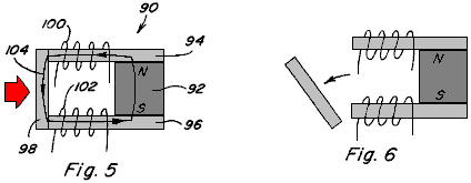
Fig.5 and Fig.6 are side views of a permanent magnet device including a permanent magnet having pole pieces positioned against the pole faces thereof and including a movable armature;
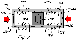
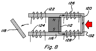
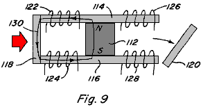
Fig.7, Fig.8 and Fig.9 are side views of a permanent magnet device including a permanent magnet having pole pieces positioned against the pole faces thereof to provide two magnetic flux paths and including a movable armature which can be positioned along each magnetic flux path;
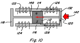

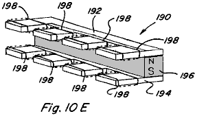

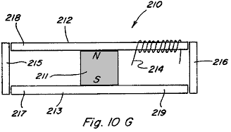
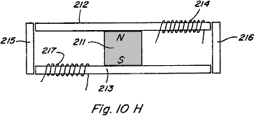
Figs.10, 10A-10H are perspective views of various embodiments of permanent magnet 5 control components which include two or more magnetic flux paths;
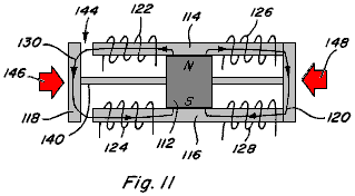


Figs.11, 11A-11F are side views of a permanent magnet device including a permanent magnet having pole pieces positioned against the pole faces thereof and including a movable armature and a permanent bypass extending between the pole pieces;
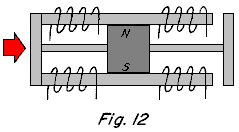
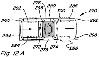
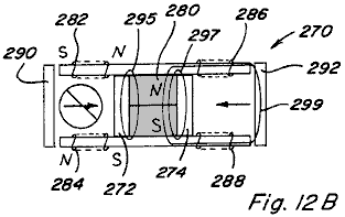
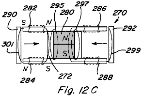
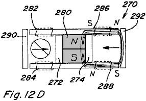

Figs.12, 12A-12E are side views of a two path permanent magnet device including two bypasses;
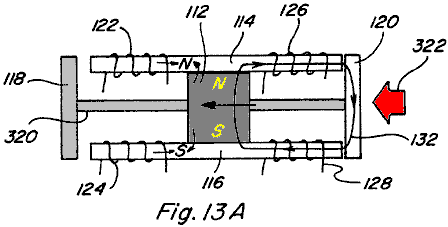
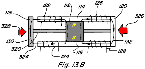
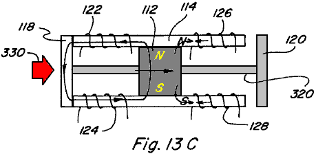
Figs.13A-13C are side views of a permanent magnet linear reciprocating device;
Fig.14 is a side view of an electromagnetic linear reciprocating device;
Fig.15 is a side view of a two path permanent magnet device showing control coils energised in an exceeding manner;

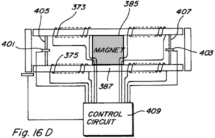
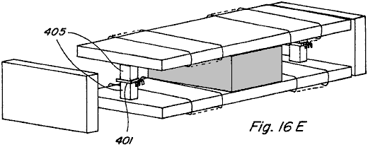
Figs.16A-E are a side view of a linear reciprocating device with control coils energised in an exceeding manner;
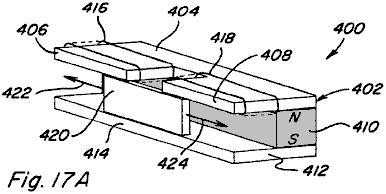
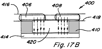

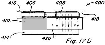
Figs.17A-17D depict another embodiment of a linear reciprocating device;

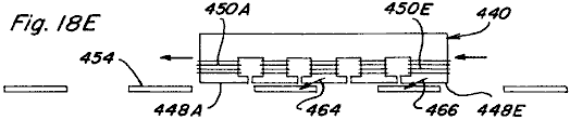
Figs.18A-18E show a linear motion device;
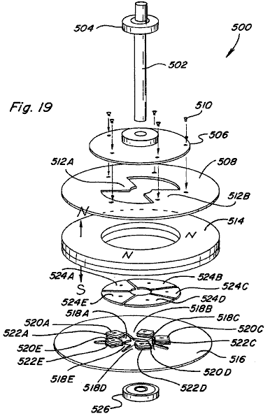
Fig.19 is an exploded perspective view of a rotary motion device;
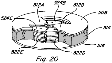
Fig.20 is a partial assembled and cut away view of the rotary motion device of Fig.19;
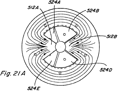
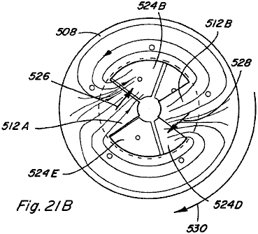
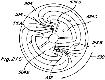
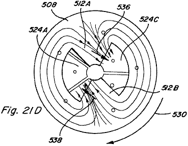
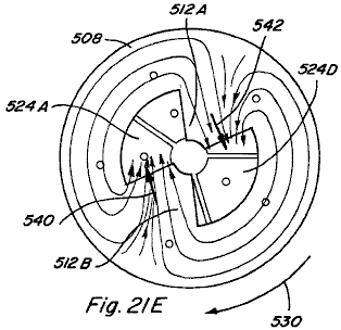
Figs.21A-21E are top views of the partial assembly of Fig.20, which views depict rotational motion thereof,
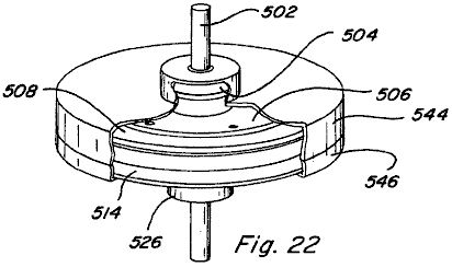
Fig.22 is an assembled, cut-away view of the rotary motion device of Fig.19 including a housing;
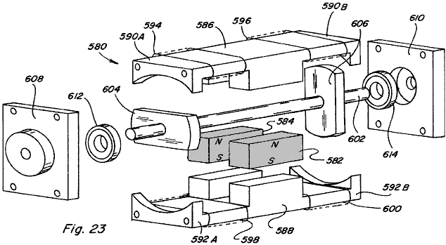
Fig.23 is an exploded perspective view of another embodiment of a rotary motion device;
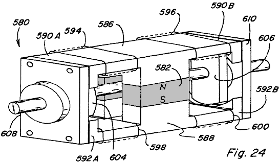
Fig.24 is a perspective view of the rotary motion device of Fig.23 as assembled;

Figs.25A-25B are end views of the rotary motion device of Fig.24 with the end cap removed to expose the rotor member;
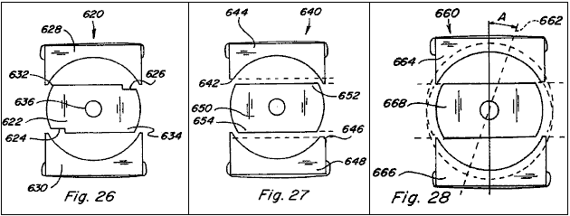
Figs.26-28 show end views of various configurations for skewing the direction of rotation in the rotary motion device of Fig.24;
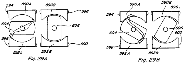
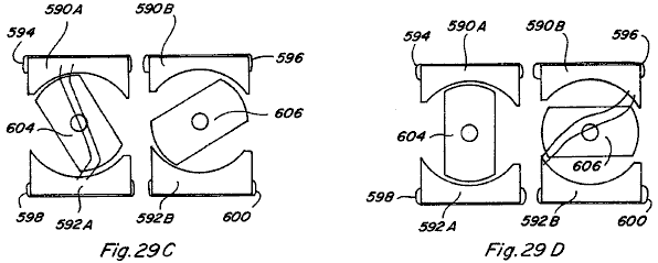
Figs.29A-29D are end views of the rotary motion device of Fig.24 illustrating a sequence of its rotational movements;
Fig.30 is an exploded partial perspective view of another embodiment of a rotary motion device;
Fig.31 is a perspective view of the rotary motion device of Fig.30 as assembled
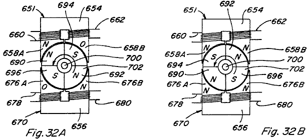
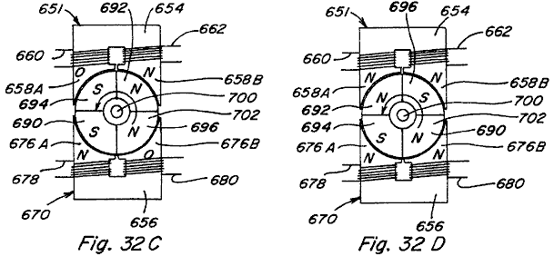
Figs.32A-32D are top views of the rotary motion device of Fig.31 illustrating it’s rotational movement;
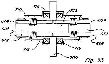
Fig.33 is a side view of the rotary motion device of Fig.31 as assembled and including a housing;
Fig.34 is a perspective view of another embodiment of a rotary motion device;

Fig.35 is a top view of the rotary motion device of Fig.34;

Fig.36 is a perspective view of the permanent magnet rotor member of the rotary motion device of Fig.34;
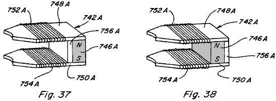
Fig.37 and Fig.38 show alternative configurations for the control component incorporated into the rotary motion device of Fig.34;
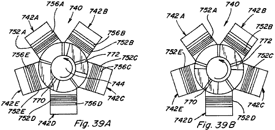

Figs.39A-39D are top views of the rotary motion device of Fig.34 and depict its rotational movement;

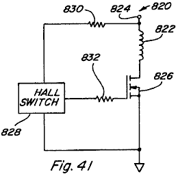
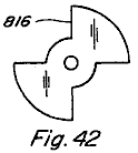
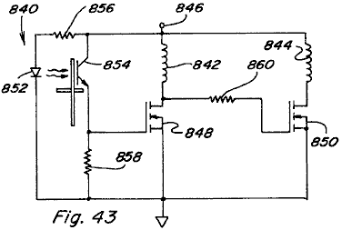
Figs.40-44 are alternative variations of the circuit for controlling the timed energisation of control coils in the various devices of the present invention;

Figs.45A-45C and Figs.45X-45Z are side views of two path power conversion devices;
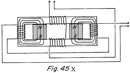
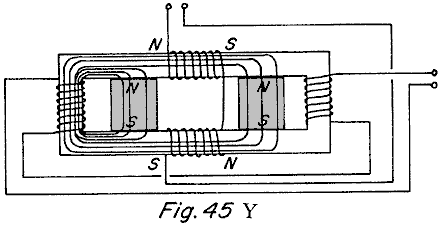
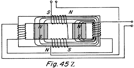
Fig.46 is a schematic view of the permanent magnet portion of a rotor for use in some embodiments of the present device;

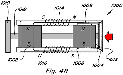
Fig.47 and Fig.48 show other embodiments of a linear motion device;

Fig.49 is a top view of another embodiment of a rotating motor like construction; and
Fig.50 is a schematic view of one of the three stator portions of the device shown in Fig.49.
DETAILED DESCRIPTION OF THE DRAWINGS
Referring now to the drawings, Figs.1-4 are provided to facilitate an understanding of various aspects or features of the technology utilised in the present invention. Fig.1 depicts a device 10 having a magnetic flux producing member 12 which may be a permanent magnet or electromagnet with magnetic poles 14 and 16 as shown. Pole pieces 18 and 20 are positioned adjacent respective poles 14 and 16 to provide a path for the magnetic flux of member 12. Each pole piece 18 and 20 has a pole piece end face 22 and 24. As used throughout this specification, it is understood that a pole piece, regardless of its shape or size, is preferably formed of soft iron, steel or some other magnetic material, with the preferred material being one which provides low reluctance, exhibits low hysterisis, and has a high magnetic flux density capability. Accordingly, the various pole pieces disclosed and described herein could likewise be of laminate type construction.
Referring again to Fig.1 an armature 26, also formed of magnetic material, is shown with end faces 28 and 30 which are positioned and sized for being placed adjacent pole piece end faces 22 and 24, such that when so positioned a substantially continuous low reluctance path 32 is provided for magnetic flux from north pole 14, through pole piece 18, through armature 26, through pole piece 16, and to south pole 16. The magnetic flux travelling along such path 32 results in a force which tends to hold armature 26 in position aligned with pole piece end faces 22 and 24. The resulting magnetic coupling or holding force F provided between adjacent pole piece end face 22 and armature end face 28, and between adjacent pole piece end face 24 and armature end face 30, can be approximated by the following equation:
![]()
where B is the magnetic flux density passing through the adjacent end faces and A is the surface area of the adjacent end faces. Assuming that if B is uniform throughout flux path 32 and that the area A of all end faces 22, 24, 28, and 30 is the same, then the total holding force FT26 of armature 26 against pole pieces 18 and 20 will be:
![]()
In Fig.2 a device 40 having the same magnetic flux producing member 12 with magnetic poles 14 and 16 is shown. Pole pieces 42 and 44 are positioned adjacent respective pole faces 14 and 16 to provide two paths, as opposed to one above, for the magnetic flux of member 12. In particular, pole piece 42 includes a first path portion 46 extending beyond a perimeter of north pole face 14 in one direction and a second path portion 48 extending beyond the perimeter of north pole face 14 in another direction. Similarly, pole piece 44 includes a first path portion 50 extending beyond the perimeter of south pole face 16 in one direction and a second path portion 52 extending beyond the perimeter of south pole face 16 in another direction. Each pole piece path portion 46, 48, 50, 52 includes a respective end face. A first armature 54 which can be positioned adjacent to the end faces of pole piece path components 48 and 52 provides a first magnetic flux path 56 and a second armature 58 is which can be positioned adjacent the end faces of pole piece path components 46 and 50 provides a second magnetic flux path 60. If the flux carrying area along flux paths 56 and 60 is the same as the flux carrying area along flux path 32 of Fig.1, the magnetic flux density along each flux path 56 and 60 will be one-half the magnetic flux density along flux path 32 of Fig.1 because the same amount of flux is split between two like paths. The effect of dividing a given amount of magnetic flux along two like flux paths instead of it passing along just one flux path can be seen by examining the holding force on armature 54 as compared to the holding force on armature 26 of Fig.1. As already noted the magnetic flux density along path 56 will be one-half that along flux path 32 and thus the total holding force FT54 can be determined as:
![]()
It is therefore seen that dividing the same amount of magnetic flux along two flux paths rather than along one flux path reduces the magnetic holding or coupling force on an armature to one-fourth rather than one-half as might have been expected. This unexpected magnetic holding or coupling force differential, resulting from multiple flux paths, can provide advantageous properties in linear, reciprocating, and rotary motion devices.
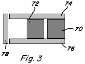

Referring now to Fig.3 and Fig.4, the behaviour of multiple magnetic flux sources arranged in parallel and series is described as compared to a single flux source. When identical flux sources or magnetic flux producing members 70 and 72 are positioned in parallel as shown in Fig.3 with pole pieces 74 and 76 positioned adjacent the poles thereof to provide a flux path through armature 78, the flux density B through armature 78 is double what the flux density would be if only one magnetic flux producing member were present. However, the field intensity H resulting from the two members 70 and 72 remains unchanged. This result holds true regardless of whether members 70 and 72 are both permanent magnets, are both electromagnets, or are a combination of one permanent magnet and one electromagnet. On the other hand, the properties resulting from magnetic flux producing members 80 and 82 arranged pole-to-pole in series between pole pieces 84 and 86, with armature 88, as shown in Fig.4, will vary depending on the nature of the members 80 and 82.
In a first case, if both members 80 and 82 are permanent magnets, the magnetic field intensity H resulting from the two permanent magnets will be double that of one permanent magnet and the flux density B through armature 88 will be the same as what the flux density would be if only one permanent magnet type member were present.
In a second case, if both members 80 and 82 are electromagnets, the field intensity H again doubles and the flux density B increases according to the B/H curve or relationship of the pole piece 84, 86 and armature 88 materials.
In a third case, if member 80 is a permanent magnet and member 82 is an electromagnet, the field intensity H again doubles, but, since the permanent magnet is near flux density saturation Br the flux density can only be increased from Br to Bmax of the permanent magnet. At the point where electromagnet-type member 82 contacts permanent magnet-type member 80 the flux from the electromagnet-type member 82 couples with the flux of the permanent magnet-type member 82 until the flux density through permanent magnet-type member 80 reaches Bmax. At that point additional flux from electromagnet-type member 82 does not contribute to the flux density along the flux path unless a bypass path around the permanent magnet-type member is provided. Use of such bypass paths will be described below.
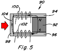
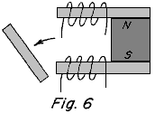
Controlling the flow of flux along both one and multiple flux paths is best described with reference to Figs.5-9. In Fig.5 and Fig.6 a permanent magnet device 90 including a permanent magnet 92 having pole pieces 94 and 96 positioned adjacent to it’s pole faces, and an armature 98 completing a low reluctance path 104 from pole to pole is shown. Control coils 100, 102 are positioned along path 104. When control coils 100, 102 are not energised, the magnetic flux of permanent magnet 92 follows path 104 as shown and armature 98 is held in place against pole pieces 94, 96 due to the resulting magnetic coupling forces. However, if coils 100, 102 are energised to provide an equal but opposing magnetic flux to that of permanent magnet 92, the result is that the magnetic flux of permanent magnet 92 is blocked and no magnetic flux traverses the path which includes armature 98 and therefore no magnetic coupling forces act on armature 98 allowing it to fall away as shown in Fig.6. The permanent magnet device 90 is useful, although as will become apparent below, it is more advantageous to provide multiple flux paths rather than one.
In this regard, in Fig.7 a permanent magnet device 110 includes a permanent magnet 112 having pole pieces 114, 116 positioned adjacent the pole faces of it, with armatures 118, 120 completing two low-reluctance paths 130, 132 from pole to pole thereof. Control coils 122, 124 are positioned along path 130 and control coils 126, 128 are positioned along path 132. The two paths provided are assumed to be of equal reluctance. With no coils energised, the magnetic flux of permanent magnet 112 divides equally along flux path 130 and flux path 132 such that both armatures 118, 120 are subjected to a magnetic coupling force which holds them in place against pole pieces 114, 116.
If coils 122, 124 are energised to provide a magnetic flux equal to but opposing the magnetic flux which travels along flux path 130 from permanent magnet 112 when no coils are energised, the result is that the magnetic flux of permanent magnet 112 is blocked and no magnetic flux traverses the path which includes armature 118 and therefore no magnetic coupling forces act on armature 118 allowing it to fall away as shown in Fig.8. Further, the magnetic flux traversing path 132 will be double that of when no coils are energised and therefore the magnetic coupling force on armature 120 will be about four (4) times that of when no coils are energised. By energising coils 126, 128 in an opposing manner a similar result would be achieved such that armature 120 would fall away and such that the magnetic coupling force on armature 118 would be increased.
If coils 122, 124 are energised to provide a magnetic flux equal to and aiding the magnetic flux which travels along flux path 130 when no coils are energised, the result is that the control coils couple completely with the magnetic flux of permanent magnet 112 and no magnetic flux traverses the path which includes armature 120 and therefore no magnetic coupling forces act on armature 120 allowing it to fall away as shown in Fig.9. Further, the magnetic flux traversing path 130 will be double that of when no coils are energised and therefore the magnetic coupling force on armature 118 will be about four (4) times that when no coils are energised. By energising coils 126, 128 in an aiding manner a similar result would be achieved such that armature 118 would fall away and the magnetic coupling force on armature 120 would be increased.
Based on the foregoing, it is seen that the full magnetic coupling force available from the permanent magnet 112, can be switched from one path to another path by the application of one half the power it would require for a coil alone to produce the same magnetic flux along one path. The ability to switch the full magnetic coupling force easily from one path to another, allows for efficient reciprocating, linear, and rotary motion and power conversion to be achieved.
The basic device utilised to achieve permanent magnet flux division and to control such permanent magnet flux division is defined herein as a "permanent magnet control component," various configurations of which are shown by way of example only, and not by way of limitation, in Figs.10A-10F. Fig.10A depicts a permanent magnet control component 150 in which pole pieces 152 and 154 are positioned adjacent to the pole faces of permanent magnet 156 to provide two magnetic flux paths extending from opposite sides of permanent magnet. Control coils 158 are positioned along each path.
Fig.10B depicts a permanent magnet control component 160 in which pole pieces 162 and 164 are positioned against the pole faces of permanent magnet 166 to provide two spaced, adjacent magnetic flux paths extending from the same side of permanent magnet 166. Control coils 168 are positioned along each path.
Fig.10C depicts a permanent magnet control component 170 in which pole pieces 172 and 174 are configured so as to be positioned adjacent the pole faces of permanent magnet 176 so as to provide four flux paths, each flux path extending in a respective direction from permanent magnet 176. Control coils 178 are also positioned along each path.
Fig.10D depicts another four-path configuration of a permanent magnet control component 180 in which pole pieces 182, 184 are configured and positioned to provide four flux paths for permanent magnet 186, with a pair of spaced, adjacent flux paths extending from each side of permanent magnet 186. Control coils 188 are positioned along each path.
Fig.10E depicts another four-path configuration of a permanent magnet control component 190 in which all four flux paths formed by pole pieces 192, 194 extend from one side of permanent magnet 196. Again, control coils 198 are positioned along each flux path.
Fig.10F still further depicts a four-path configuration of a permanent magnet control component 200 in which pole pieces 202, 204 extend to one side of permanent magnet 206, with pole piece 202 defining four flux paths and with pole piece 204 including a continuous return path. Control coils 208 are positioned along each path of pole piece 202. Many other variations are possible.
Accordingly, it is seen that a variety of different configurations of permanent magnet control components are possible, in accordance with the present invention. The important considerations for division of permanent magnet flux in such permanent magnet control components include, extending each pole piece to, or beyond, the outer perimeter of the pole face of the permanent magnet in each region where a flux path is intended and assuring that the pole face of the permanent magnet intersects each of the flux paths. It is not necessary for each pole piece to include the same number of path portions extending beyond the perimeter of the respective permanent magnet pole face as noted with reference to permanent magnet control component 200. Although two control coils are shown along each of the flux paths in Figs.10A-10E, it is apparent from component 200 in Fig.10F that one control coil positioned along a flux path is generally sufficient for purposes of the present invention. Further, although in the illustrated configurations each pole piece is positioned to contact a respective pole face of the permanent magnet, a small spacing between a pole piece and its adjacent permanent magnet pole face could be provided, particularly in applications where relative movement between the subject pole piece and the permanent magnet will occur.
In its simplest form a two path permanent magnet control component only requires one control coil positioned along one of the control paths to permit the magnetic flux of a permanent magnet to be switched between the two paths. In particular, a side view of such a two path component 210 is shown in Fig.10G and includes a permanent magnet 211 pole pieces 212 and 213, and control coil 214 which may be connected to a suitable control circuit. By alternating energising control coil 214 in an opposing manner and an aiding manner the magnetic flux of permanent magnet can be switched between the path including armature 215 and the path including armature 216. When control coil 214 is energised in an opposing manner the magnetic flux will traverse the path including armature 215 and when control coil 214 is energised in an aiding manner the magnetic flux will traverse the path including armature 216. Control coil 214 could also be placed at any of the positions 217, 218, or 219 to achieve the flux path switching.
Further, in the two coils embodiment shown in Fig.10H control coil 217 is added. In such a device, flux switching can be achieved by simultaneously energising control coil 214 in a flux aiding manner and control coil 217 in a flux opposing manner, and by then simultaneously reversing the energisation of the respective control coils 214 and 217.
Reference is made to Figs.11A-11F which depict devices similar to that of Figs.5-6 except that a bypass, formed of magnetic material, is provided in each case. In device 220 of Figs.11A-11C a bypass 222 is provided from pole piece 224 to pole piece 226 and is located between permanent magnet 228 and control coils 230, 232, with armature 234 located adjacent the ends of pole pieces 224, 226. In Fig.11A with no coil energisation, magnet flux components 236 and 237 travel as shown.
When coils 230 and 232 are energised in an aiding or adding manner as in Fig.11B, the result is permanent magnet magnetic flux components 236 and 237 travelling as shown, and with the added magnetic flux component 238 from coils 230 and 232 also travelling as shown. Thus, in device 220 energising the coils in an aiding manner results in an increased magnetic coupling force on armature 234.
In Fig.11C coils 230, 232 are energised in an opposing exceeding manner which results in permanent magnetic flux components 236 and 237 travelling as shown and excess magnetic flux component 238 travelling as shown. Thus, in device 220 energising the coils in an opposing exceeding manner results in magnetic coupling force on armature 234, albeit smaller than that in the aiding exceeding case.

In device 240 of Figs.11D-11F a bypass 242 is provided between pole piece 244 and pole piece 246 but is located on an opposite side of permanent magnet 248 as compared to control coils 250, 252 and armature 254. Permanent magnet flux components 256 and 257 are shown for no coil energisation in Fig.11D. In Fig.11E the paths of permanent magnet flux components 256 and 257, as well as excess coil magnetic flux 258, are shown when coils 250, 252 are energised in an aiding exceeding manner.
In Fig.11F the path of each magnetic flux component 256, 257, and 258 is shown when coils 230, 232 are energised in an opposed exceeding manner.
Figs.12A-12E depict a device 270 similar to that shown in Figs.7-9 except that bypasses 272 and 274 are provided from pole piece 276 to pole piece 278. Bypass 272 is located between permanent magnet 280 and control coils 282, 284 and bypass 274 is located between permanent magnet 280 and control coils 286, 288. Armatures 290 and 292 are also provided. When no coils are energised permanent magnet magnetic flux components 294, 296, 298, and 300 travel as shown in Fig.12A.
If coils 282, 284 are energised in an opposing manner permanent magnet flux components 295, 297, and 299 travel as shown, with no flux component traversing the path which includes armature 290 and therefore no magnetic coupling force acting thereon. This would be the case when coils 282, 284 are energised to the level where the coils magnetic flux just blocks, but does not exceed, the magnetic flux component 294 (Fig.12A) from permanent magnet 280. However, if coils 282, 284 are energised in an opposed exceeding manner an excess coil magnetic flux component 301 is produced which travels a path including armature 290 and bypass 272 results as shown in Fig.12C.

Coils 286, 288 may be energised in an aiding manner such that all permanent magnet magnetic flux travels along the path which includes armature 292 as shown in Fig.12D. If coils 286, 288 are energised in excess of the level of Fig.12D then the excess magnetic flux component 304 traverses the path which includes armature 292 and bypass 274 as shown in Fig.12E, thereby increasing the magnetic coupling force on armature 292 as compared to Fig.12D. The advantage of incorporating such bypasses into permanent magnet control components in certain applications will become apparent below.
Reciprocating Motion
As mentioned above, controlling the path of magnetic flux from a permanent magnet can be useful in a variety of applications such as achieving reciprocating motion. In this regard, if the device 110 of Figs.7-9 is modified such that armatures 118 and 120 are fixed to a sliding shaft 320 as shown in Figs.13A-13C, and if the distance between the armatures is greater than the end to end length of pole pieces 114, 116, limited linear motion in two directions (left and right in Figs.13A-13C), and therefore linear reciprocating motion, can be achieved by the timed, alternate delivery of electrical signals to control coils 122, 124 and control coils 126, 128. By way of example, Fig.13A represents the position of shaft connected armatures 118, 120 when coils 122, 124 are energised in an opposing manner to block the flux of permanent magnet 112 such that all magnetic flux traverses path 132 as shown and such that the resulting magnetic coupling force acts to the left as indicated by arrow 322.
As shown in Fig.13B when coils 122, 124 are de-energised the magnetic flux from permanent magnet 112 can again travel along path 130 through armature 118. However, due to the air gap 324 between armature 118 and pole pieces 114, 116 the reluctance along path 130 will be significantly greater than the reluctance along path 132. Accordingly, the amount of magnetic flux which flows along path 130 will be less than the amount of magnetic flux which flows along path 132 such that the magnetic coupling force on armature 118 acting to the right will be significantly less than the magnetic coupling force on armature 120 acting to the left as shown by arrows 326 and 328, which arrows are sized to represent the strength of the respective directional force.
Fig.13C represents the position of shaft connected armatures 118, 120 after coils 126, 128 are energised in a manner to oppose the flux of permanent magnet 112 such that all flux traverses path 130 and the resulting magnetic coupling force on armature 118, depicted by arrow 330, moves the shaft 10 connected armatures 118, 120 to the right.
Control coils 122, 124 and 126, 128 could also be energised in a flux aiding manner to achieve the same result. In such a device, Fig.13A would represent coils 126, 128 energised to aid magnetic flux along path 132, Fig.13B would again represent no coils energised, and Fig.13C would represent coils 122, 124 energised to aid magnetic flux along path 130.
Thus, by alternately energising and de-energising control coils 122, 124 and 126, 128 a linear reciprocating motion of shaft connected armatures 118, 120 may be achieved. Further, such reciprocating motion may be achieved by energising the coils in either an opposing or aiding manner. The magnetic coupling force exerted on a given armature when 20 the control coils are energised to establish all magnetic flux along a single path which includes that armature is significantly greater than the magnetic coupling force which would be exerted on such armature by an identical energisation of the control coils in the absence of the permanent magnet.
This is demonstrated with reference to Fig.14 which depicts a reciprocating device 340 in which only coils or electromagnets are utilised. As shown armatures 342 and 344 are connected by shaft 346, and each armature 342, 344 includes a respective U-shaped pole path piece 348, 350 which pole path pieces are mechanically connected by a non-magnetic material 352. Each pole path piece 348 and 350 has respective control coils 354, 356 and 358, 360 positioned along them. By comparison with the device of Figs.13A-13C, if coils 358, 360 of device 340 are energised to cause magnetic flux flow in either direction, clockwise or counterclockwise, along path 362, the amount of electrical energy which would be required in order to achieve the same magnetic coupling force on armature 344 as achieved on armature 120 above in Fig.13A would be twice that delivered to coils 122, 124 or 126, 128 in Fig.13A. It is therefore demonstrated, that by controlling or switching the flow of magnetic flux from a permanent magnet between at least two different paths results in greater coupling forces per unit of input electrical energy, and therefore that such control or switching will enable more work to be achieved per unit of input electrical energy.
As described above, if a coil is energised beyond the point where the magnetic flux produced by the coil aiding the amount of the permanent magnet's flux that is either opposed or aided, the extra magnetic flux needs a low reluctance path between the poles of the coil that produces the excess magnetic flux. If a complete low-reluctance path is not provided for the excess magnetic flux, there is little potential for taking advantage of the excess magnetic flux in terms of producing additional magnetic coupling forces. The path for such excess flux cannot be through a permanent magnet member. In assemblies which include an armature on each path, the armature will provide the necessary low-reluctance path.
Referring to Fig.15, various components of the magnetic flux in device 110 (Figs.7-9) are depicted by numerals 380, 382, and 384 for the case when coils 122, 124 are energised to oppose the magnetic flux of permanent magnet 112 in an amount which exceeds the level of magnetic flux which permanent magnet 112 would cause to flow through armature 118 when no coils are energised. Fig.15 is likewise representative of the case when coils 126, 128 are energised to aid the magnetic flux of permanent magnet 112 by an amount which exceeds the level of magnetic flux which permanent magnet 112 would cause to flow through armature 118 when no coils are energised. In particular, magnetic flux component 380 represents the magnetic flux of permanent magnet 112 which normally flows through the path including armature 120; magnetic flux component 382 represents the magnetic flux of permanent magnet 112 which is diverted by the opposing field of coils 122, 124 so as to traverse the path which includes armature 120; and magnetic flux component 384 represents the magnetic flux produced by coils 122, 124 which is in excess of the diverted magnetic flux 382. As shown, the excess magnetic flux 384 produced by coils 122, 124 traverses the path which includes armature 120 and bypasses permanent magnet 112 so as to also traverse the path which includes armature 118. Thus, the excess magnetic flux produced by coils 122, 124 adds to the permanent magnet flux traversing the path which includes armature 120, thus increasing the magnetic coupling force on armature 120, while at the same time providing a magnetic coupling force on armature 118.
In a reciprocating device where armatures 118 and 120 are connected by shaft 320 as shown in Figs.13A-13C and again in Fig.16A, excess magnetic flux 384 will increase magnetic coupling force 390 on armature 120 acting to the left. However, because such excess flux 384 also traverses the path which includes armature 118, such excess magnetic flux 384 also results in a magnetic coupling force 392 on armature 118 which acts to the right. Even though excess magnetic flux 384 traversing the path which includes an armature 118 has an opposite polarity to that which would traverse the path due to permanent magnet 112, the magnetic coupling force on armature 118 still acts to the right because armature 118 is not polarity sensitive, that is, armature 118 will be attracted regardless of the direction of the magnetic flux traversing the path. The overall effect is that a resultant force which is the difference between force 390 and force 392 will act on the shaft-connected armatures 118, 120. However, if armatures 118 and 120 were formed by permanent magnets having polarities as shown at the top and bottom of such armatures, the force acting on each armature would be in the same direction and therefore additive.
In this regard reference is made to Fig.16B in which a two path device 371 having four control coils 373, 375, 377 and 379 is shown with the illustrated armatures being formed by permanent magnets 381 and 383 having polarities as shown. With no coils energised both permanent magnet armatures 381 and 383 are attracted to the ends of pole pieces 385 and 387. With coils 373, 375 energised in an opposing manner and coils 377, 379 energised in an aiding manner, the attractive force on permanent magnet armature 383 will generally increase and the attractive force on permanent magnet armature 381 will generally decrease.
This is demonstrated with reference to the graph of Fig.16C which depicts a graph of the current flowing in the control coils on the x-axis verses the magnetic flux in gauss on the y-axis with line 389 representing the flux along the aiding side of device 371 and line 391 representing the flux along the opposing side of device 371. As shown, the magnetic flux on the coil opposing side decreases as the coil current increases and passes through zero at point 393. After point 393, reverse magnetic flux begins to be produced and would result in a repelling force on permanent magnet armature 381. In some applications, particularly those where permanent magnet armatures and rotors are not utilised, it is critical to recognise point 393 so that reverse magnetic flux is not produced.
In this regard, reference is made to Fig.16D and Fig.16E, in which use of Hall Effect switches 401 and 403 is made to enable control of the coil energising current in situations where it is desirable to prevent reverse magnetic flux. As shown, small bypasses 405 and 407 are provided with Hall Effect switches 401 and 403 positioned in gaps along them, the switches being connected to control circuit 409. As the flux travelling along the bypass path falls to zero, the Hall Effect switch can be utilised to prevent further energisation of the control coils so that no reverse flux is created.
Another embodiment of a device 400 which would provide reciprocating motion is shown in Figs.17A-17D in which a permanent magnet control component 402 having two flux paths may is provided. A first pole piece 404, has two spaced, adjacent path portions 406 and 408 extending beyond the perimeter of the pole face of permanent magnet 410, and a second pole piece 412 includes only one continuous portion 414 extending beyond the perimeter of the pole face of permanent magnet 410, each path portion 406 and 408 of pole piece 404 being substantially aligned with at least a part of portion 414 of pole piece 412. Control coil 416 is positioned along pole piece path portion 406 and control coil 418 is positioned along pole piece portion 408. An armature 420 is positioned in the region between pole piece path portions 404, 406 and pole piece portion 414 and is free to slide from side to side as shown by arrows 422 and 424.
A front view of component device 400 with no coils energised and armature 420 at a mid-point depicts flux flowing from the north pole face of permanent magnet 410, through each of pole piece path portions 406 and 408, through armature 420, and returning to the south pole face through pole piece portion 414. Thus, the magnetic flux divides equally along two paths. If coil 416 is energised in an aiding manner, or if coil 418 is energised in an opposing manner, all or a majority of the magnetic flux of the permanent magnets can be made to flow through pole piece portion 406 so that a resulting magnetic coupling force on armature 420 causes it to move to the left as shown in Fig.17C.
Likewise, if control coil 416 is energised in an opposing manner, or if control coil 418 is energised in an aiding manner, all or a majority of the permanent magnet flux can be made to flow through pole piece path portion 408 such that a resulting magnetic coupling force on armature 420 causes it to move to the right as shown in Fig.17D. Accordingly, by alternately energising and de-energising coils 416 and 418 a reciprocating motion of armature 420 may be achieved.
Linear Motion
Referring now to Figs.18A-18E, linear motion in accordance with the present invention is described. In particular, a permanent magnet control component 440 including a permanent magnet 442 with a pole piece 444 positioned against it’s north pole face and a pole piece 446 positioned against it’s south pole face is shown in an exploded view in Fig.18A and assembled in Fig.18B.
Pole piece 444 includes five path portions 448A-448E which extend beyond the edge of the north pole face of permanent magnet 442 to one side of it and at respective positions along it’s length, and it has path portion 448A-448E each with a control coil 450A-450E positioned around them. Pole piece 446 includes one portion 452 extending beyond the edge of the south pole face of permanent magnet 442 to the one side of it, and this portion 452 extends along the entire length of permanent magnet 442. A number of armatures 454 define a path of relative movement between permanent magnet control component 440 and such armatures 454, and by providing timed energisation of given control coils 450A-450E such relative movement can be achieved.
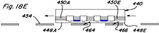
The sequence of side views depicted in Figs.18C-18E illustrate such relative movement,
with coils 450A, 450C and 450E being energised in an opposing manner simultaneously in Fig.18C,
with coils 450A and 450D being energised simultaneously in an opposing manner in Fig.18D, and
with coils 450B and 450D being energised simultaneously in an opposing manner in Fig.18E.
In Fig.18C, magnetic flux will only flow along path portions 448B and 448C of pole piece 444 causing resultant magnetic coupling forces depicted by arrows 456, 458 which act to move permanent magnet control component 440 to the left, assuming armatures 454 are fixed. Similarly, due to the timing of subsequent coil energisation resultant magnetic forces depicted by arrows 460, 462 in Fig.18D and arrows 464, 466 in Fig.18E act to continue movement of permanent magnet control component 440 to the left. Thus, if permanent magnet control component 440 were fixed to a device or structure, controlled movement of the device or structure along the path defined by armatures 454 could be achieved. Conversely, if permanent magnet control component 440 were fixed and armatures 454 were located on a device or structure, controlled movement of the device or structure could also be achieved. It is also easily recognised that by varying the coil energisation sequence and timing relative movement in the opposite direction can be achieved. Further, if the permanent magnet was doughnut shaped and the armatures were arranged in a circumferential pattern, rotary motion would likewise be achievable.
Rotary Motion
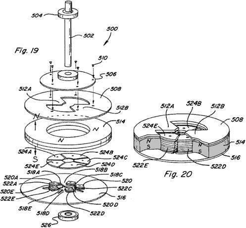
One embodiment of a rotary motion device or motor 500 which incorporates various permanent magnet flux control aspects of the present invention is shown in the exploded view of Fig.19 and in the partial assembled view of Fig.20. Motor 500 includes a rotor assembly which includes a shaft 502 and associated upper bearing 504, a non-magnetic disk member 506 mounted for rotation with shaft 502, and a rotor pole piece 508 which is mounted for rotation with disk member 506 such as by the use of screws 510. Rotor pole piece 508 includes a ring-shaped portion having two inwardly extending magnetic flux path portions 512A and 512B. A stator assembly of motor 500 includes a doughnut or ring-shaped permanent magnet 514 having an upwardly directed north pole face positioned adjacent and in close proximity to rotor pole piece 508, and a downward directed south pole face positioned adjacent and in contact with a stator pole piece 516. Stator pole piece includes a ring-shaped portion having five inwardly projecting path portions 518A-518E. Each path portion includes a respective winding post 520A-520E extending therefrom and having a respective control coil 522A-522E wound on it. Stator pole piece faces 524A-524E are which can be positioned on respective winding posts 518A-518B and, as shown in the partial assembly of Fig.20, are substantially aligned with the top surface of permanent magnet 514 so as to be which can be positioned adjacent rotor path portions 512A and 512B when aligned therewith. Each of winding posts 518A-518E and stator pole piece faces are formed of magnetic material, and although shown as separate pieces, an integral, one piece stator could be formed with similar winding posts and pole piece faces machined on it. Lower bearing 526 is also shown.
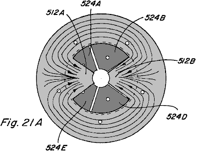
Figs.21A-21E illustrate top views of the partial assembly of Fig.20 with magnetic flux shown. In Fig.21A magnetic flux travel when none of coils 522A-522E are energised is depicted. Disregarding leakage flux, due to the low-reluctance path provided by rotor pole piece path portions 512A and 512B, the majority of magnetic flux from the north pole face of permanent magnet 514 will travel radially inward along one of such path portions before passing downward through the stator assembly and returning to the south pole face of permanent magnet 514. It is noted that rotor pole piece 508 includes two path portions and stator pole piece 516 includes five path portions such that rotor pole piece path portions 512A and 512B will always be skewed relative to the stator pole piece faces 524A-524E. Only one rotor pole piece path portion can directly align with a stator pole piece face at a given time. By alternately energising the control coils of each of the stator pole piece paths, rotary motion of the rotor may be achieved.
In particular, referring to Figs.21B-21D, an energising sequence which results in such rotary motion is described. In Fig.21B, control coils 522A and 522C are energised in a permanent magnet flux opposing manner. Permanent magnet magnetic flux travelling along rotor pole piece path portion 512A tends to traverse to stator pole piece face 524B causing a magnetic coupling force indicated by arrow 526. Likewise, permanent magnet flux travelling along rotor pole piece path portion 512B tends to traverse to stator pole piece face 524D causing a magnetic coupling force indicated by arrow 528. The result is rotation of rotor pole piece 508 in a clockwise direction as indicated by arrow 530.
Referring to Fig.21C, just after rotor pole piece path portion 512B is no longer aligned with stator pole piece face 524D, control coil 522C is de-energised and control coil 522D is energised in an opposing manner such that the permanent magnet flux travelling along rotor pole piece path 512B tends to traverse to stator pole piece face 524E resulting in magnetic coupling force indicated by arrow 532. Control coil 522A remains energised such that a magnetic coupling force indicated by arrow 534 results. Accordingly, clockwise rotation of rotor pole piece 508 is continued.
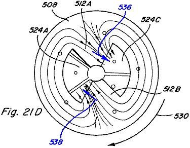
In Fig.21D, just after rotor pole piece path portion 512A is no longer aligned with stator pole piece face 524B, control coil 522A is de-energised and control coil 522B is energised in a permanent magnet magnetic flux opposing manner such that the permanent magnet magnetic flux travelling along rotor pole piece path 512A tends to traverse to stator pole piece face 524C such that a magnetic coupling force indicated by arrow 536 results. Control coil 522D remains energised such that a magnetic coupling force indicated by arrow 538 results, and clockwise rotation of rotor pole piece 508 is continued.
As shown in Fig.21E, just after rotor pole piece path portion 512B is no longer aligned with stator pole piece face 524E, control coil 522D is de-energised and control coil 522E is energised in a permanent magnet magnetic flux opposing manner such that the permanent magnet magnetic flux travelling along rotor pole piece path 512B tends to traverse to stator pole piece face 524A such that a magnetic coupling force indicated by arrow 540 results. Control coil 522B remains energised such that a magnetic coupling force indicated by arrow 542 results, and clockwise rotation of rotor pole piece 508 is continued.
Thus, by alternating energising and de-energising control coils 522A-522E, in a predetermined timed sequence based upon rotation of the rotor assembly, continued rotation movement of rotor pole piece 508 may be achieved. Such an energisation/de-energisation scheme can be achieved utilising circuitry common in the art, such as the control circuitry described in Applicant's U.S. Pat. Nos. 5,463,263 and 5,455,474, as well as various of the circuit configurations described below.
Referring now to Fig.22, an assembled view of rotary motor 500 is shown including a housing or cover formed by an upper housing member 544 and a lower housing member 546, with portions of each housing member cut away to expose motor structure described above. It is recognised that such housing members 544 and 546 should be constructed from a non-magnetic material, and likewise that motor shaft 502 and bearings 504, 526 should be constructed from a non-magnetic material.
In another embodiment, a rotary motion device or motor 580 in accordance with the present invention is shown in an exploded perspective view in Fig.23 and in an assembled perspective view in Fig.24. Two spaced permanent magnets 582 and 584 are positioned between stator pole pieces 586 and 588. Stator pole piece 586 includes two path portions 590A and 590B extending away from permanent magnets 582, 584 in opposite directions. Likewise, stator pole piece 588 includes two path portions 592A and 592B extending away from permanent magnets 582, 584 in opposite directions and which can be aligned with stator pole piece path portions 590A and 590B. Control coils 594, 596, 598, and 600 are each positioned along a stator pole piece path portion as shown. A non-magnetic shaft 602 includes a pair of matching elongated rotor members 604 and 606, formed of magnetic material, mounted at spaced locations on the shaft and being set at an angle to each other, shaft 602 passing between spaced permanent magnets 582 and 584. Two end cap members 608 and 610, made from non-magnetic material, are attached to the ends of stator pole pieces 586 and 588 and are configured for receiving shaft 602 and respective bearings 612 and 614.
The ends of the stator pole pieces 506 and 508 are configured for a given desired coupling relationship with rotor members 604 and 606. For example, as shown in the exemplary end views of Fig.25A and Fig.25B, with end cap 608 removed, the end of stator pole piece 586 may include an curved portion 616 which is configured to create a variable-reluctance air gap 618 with elongated rotor member 604. The end of stator pole piece 588 includes an curved portion 620 which is also configured to create a variable-reluctance air gap 622 with rotor member 604.
In particular, portion 618 includes a circumferential curvature which has a centre point offset below the axis of rotation of shaft 602 and rotor member 604 as indicated by circle 624 shown in shadow. Similarly, portion 620 includes a circumferential radius of curvature which has a centre point offset above the axis of rotation of shaft 602 and rotor member 604. When magnetic flux is passing along the path which includes a given end of the assembly, maximum coupling between the rotor member and stator pole pieces occurs when the rotor is positioned as shown in Fig.25B. Accordingly, the illustrated rotor member and stator pole piece configurations of themselves do not provide any skewing to the direction of rotation of the rotor assembly.
In this regard, various configurations for the rotor and ends of the stator pole piece are shown in the end views of Figs.26-28, which configurations provide skewing the direction of rotation. In particular, in device 620 of Fig.26 a rotor member 622 having notches 624 and 626, which notches provide for greater magnetic coupling with the stator pole pieces 628 and 630 at corners 632 and 634 such that rotation is skewed in the clockwise direction. If notches were instead located at corners 632 and 634, skewed rotation in the counterclockwise direction would be the result. In device 620 such counterclockwise rotation could also be achieved by removing rotor 622 from shaft 636, flipping it end to end, and replacing it on shaft 636.
In the device 640 of Fig.27, a portion 642 of the curved end portion of stator pole piece 644 is removed and a portion 646 of the curved end portion of stator pole piece 648 is removed. This configuration results in greater magnetic coupling between rotor member 650 and stator pole piece 644 at corner 652, and greater magnetic coupling between rotor member 650 and stator pole piece 648 at corner 654, such that rotation is skewed in the counterclockwise direction. Clockwise rotation could be achieved by instead modifying the opposite side of stator pole pieces 644 and 648.
Fig.28 depicts an end view of a device 660 in which the axis 662 of the curved end portion of upper stator pole piece 664 and lower stator pole piece 666 is placed at an angle A as shown. This configuration creates an unequal variable-reluctance air gap where opposite corners of rotor member 668 are closer to stator pole pieces 664 and 666. Further, the angle at which maximum magnetic coupling between rotor member 668 and stator pole pieces 664 and 666 occurs is retarded by angle A. Rotation would be in the counterclockwise direction for the illustrated configuration.
Referring again to motor 580 of Figs.23-25, rotary motion of such device is depicted in the end views of Figs.29A-29D. In each end view the end cap has been removed to show rotation of the rotor members and in each of Figs.29A-29D an end view depicting rotor member 604 and an end view depicting rotor member 606 are shown side-by-side. In Fig.29A, rotor member 604 is defined as being at zero degrees and rotor member 606 is defined as being at ninety degrees. Control coils 594, 598 are energised in a permanent magnet magnetic flux aiding manner such that no magnetic flux passes through stator pole piece path portions 590B and 592B. This allows rotor member 606 to move out of its ninety degree position and the magnetic coupling between rotor member 604 and stator pole piece path portions 590A and 592A will cause rotation to the position shown in Fig.29B and then Fig.29C. When rotor member 604 reaches the ninety degree position shown in Fig.29D control coils 594, 598 are de-energised and control coils 596, 600 are energised in a permanent magnet magnetic flux aiding manner causing rotation to continue due to the magnetic coupling between rotor member 606 and stator pole piece path portions 590B and 592B. Thus, by alternately energising the control coils of each path with every ninety degree rotation of rotor members 604 and 606, continuous rotary motion is achieved.
The initial direction of rotation can be controlled by the circuit means used to energise control coils 594, 598 and 596, 600, which circuit means includes circuitry for detecting the angular position of the rotor members. In particular, if rotor members 604 and 606 are at rest in the position shown in Fig.29A, and coils 594, 598 are energised in an aiding manner, rotation may be clockwise or counterclockwise. If the desired direction is clockwise but upon energisation of coils 594, 598 the rotor members begin to move counterclockwise, the detection circuitry will immediately de-energise coils 594, 598 and energise coils 596, 600 so that the clockwise direction is achieved.
Further, bypasses around permanent magnets 582 and 584 could be provided in rotary motion device 580, such as those shown in Fig.12, and rotor members 604 and 606 could be formed by permanent magnets so as to take advantage of energising the control coils in an exceeding manner.
A third embodiment of a rotary motion device or motor 650 is shown in the exploded partial perspective view of Fig.30 and in the assembled partial perspective view of Fig.31. In motor 650 the stator assembly includes a control component 651 including a permanent magnet 652 having a stator pole piece 654 positioned adjacent to one pole face of the magnet and a stator pole piece 656 positioned adjacent to the opposite pole face. Stator pole piece 654 includes a path portion 658A extending to one side of permanent magnet 652 and a path portion 658B extending to the one side thereof and spaced from first path portion 658A. Control coils 660 and 662 are positioned along respective stator pole piece path portions 658A and 658B.
In the same way, stator pole piece 656 includes path portions 664A and 664B which extend in a similar manner from it so as to be aligned with stator path portions 658A and 658B respectively. Control coils 666 and 668 are positioned along respective stator pole piece path portions 664A and 664B. Positioned opposite, and facing control component 651, is a similar control component 670 including permanent magnet 672 stator pole piece 674 with path portions 676A and 676B having the control coils 678 and 680, and stator pole piece 682 with path portions 684A and 684B having their control coils 686 and 688. The end of each of the pole piece path portions 658A, 658B, 664A, 664B, 676A, 676B, 684A, and 684B is of a generally curved configuration.
A rotor assembly of motor 650 includes a non-magnetic shaft 700 having a permanent magnet rotor member 702 mounted on it and which rotates with it. Permanent magnet rotor member 702 is generally ring-shaped and segmented to include distinct north and south pole faces which reverse about every ninety degrees around them. When assembled, the top and bottom surfaces of permanent magnet rotor member 702 align with pole pieces 654, 656, 674, and 682 of the stator assembly and are preferably configured so that there is a minimal gap between the outer surface of permanent magnet rotor member 702 and the curved surfaces of the pole piece path portions.
Rotation of device 650 can be achieved by controlled, timed energising and de-energising of control coils 660, 662, 666, 668, 678, 680, 686, and 688. Exemplary rotation is demonstrated with reference to the top views of Figs.32A-32B which depict counterclockwise rotation of permanent magnet rotor member 702 through one-hundred and eighty degrees. In Fig.32A stator pole piece path portion 658A of component 651 is active and stator pole piece path portion 658B is not active, which may be achieved by energising control coil 660 in a permanent magnet magnetic flux aiding manner or by energising control coil 662 in a permanent magnet magnetic flux opposing manner. Stator pole piece path portion 676B of component 670 is active and stator pole piece path portion 676A is not active, which may be achieved by energising control coil 680 in a permanent magnet magnetic flux aiding manner or by energising control coil 678 in a permanent magnet magnetic flux opposing manner.
Thus, portions 690 and 692 of permanent magnet rotor member 702, which both have a north magnetic polarity, will be repelled by the north polarity of stator pole piece path portions 658A and 676B aligned with it. Portions 694 and 696 of permanent magnet rotor member 702, both of which have a south magnetic polarity, will be attracted to the active path portions 658A and 676B. At the instant that rotor member portion 694 becomes aligned with stator pole piece path portion 658A, as shown in Fig.32B, all coils are de-energised such that all pole piece path portions will be active as shown. Pole piece path portions 658B and 676A are then kept active while pole piece path portions 658A and 676B are made inactive. This is achieved by energising control coils 662 and 678 in a permanent magnet magnetic flux aiding manner or by energising control coils 660 and 680 in a permanent magnet magnetic flux opposing manner. Rotor member portions 690 and 692 will again be repelled by the north polarity of path portions 658B and 676A aligned with it so that rotation of permanent magnet rotor 702 is continued.
In Fig.32D all coils are shown de-energised when rotor portion 692 aligns with pole piece path portion 658A. By continuing this timed sequence of energisation and de-energisation of the control coils, continued rotary movement is achieved. As explained above, the initial direction of rotation can be controlled by circuit means which detects the initial direction of permanent magnet rotor 702 and immediately alters the coil energisation scheme if the initial direction is incorrect.
A side view of assembled motor 650 is shown in Fig.33 and includes an upper housing or enclosure portion 710, a bottom housing portion 712, upper bearing 714, and a lower bearing 716.
A fourth embodiment of a rotary motion device or motor 740 is illustrated in Figs.34-39. Motor 740 includes five stator control components 742A-742E positioned around a ring shaped permanent magnet rotor member 744 (Fig.36). As shown with reference to component 742A in Fig.37, each stator component 742A includes a permanent magnet 746A with an upper pole piece 748A positioned adjacent to one pole face and a lower pole piece 750A positioned adjacent to the opposite pole face. Control coils 752A, 754A are positioned along respective pole pieces 748A, 750A. A bypass 756A extends from pole piece 748A to pole piece 750A and is positioned between permanent magnet 746A and control coils 752A, 754A. Alternatively, bypass 756A could be provided on the opposite side of permanent magnet 746A as shown in Fig.38. Although not shown, it is anticipated that permanent magnet rotor member 744 would be mounted on an axis for rotation with it and that a motor housing or enclosure could be provided, such as shown in relation to motor 650 of Fig.33.
Referring to the top views of Figs.39A-39D, rotary motion of rotor member 744 is depicted by the sequence of views. Regions 770 and 772 in Figs.39A-39D represent the magnetic north regions of the top of permanent magnet rotor 744. In Fig.39A control coils 752E and 752C are energised in a permanent magnet aiding and exceeding manner such that regions 770 and 772 of permanent magnet rotor 744 are repulsed by components 742E and 742C while permanent magnet motor regions 774 and 776 are attracted by components 742E and 742C. The resultant coupling forces act to move permanent magnet rotor in a counterclockwise direction to the location shown in Fig.39B. Just after permanent magnet rotor region 772 passes the point shown in Fig.39C, control coil 752B is energised in a permanent magnet aiding and exceeding manner, while control coils 752E and 752C also remain energised, and counterclockwise rotation of permanent magnet rotor 744 is continued. Just after permanent magnet rotor region 772 passes by control component 742C control coil 752C is de-energised, while control coils 752E and 752B remain energised, so as to continue counterclockwise rotation. Then, just after permanent magnet rotor region 770 reaches the location shown in Fig.39D control coil 752D is energised in a permanent magnet flux aiding and exceeding manner, while coils 752E and 752B remain energised, so as to continue counterclockwise rotation. Thus, as in the other embodiments, repeated and timed energisation and de-energisation of the control coils produces the desired rotational movement.
In terms of controlling the energisation of coils in the devices described above, various electronic control circuit/switching means and electromechanical control circuit/switching machines are depicted in Figs.40-44. In circuit 800 of Fig.40 a given coil 802 is placed in series between an electrical energy source 804 and a power MOSFET 806. An LED 808 is connected to electrical energy source 804 through resistor 810 and is positioned to impinge upon a phototransistor 812 which is connected in series with resistor 814. A control input of MOSFET 806 is connected between phototransistor 812 and resistor. Accordingly, when LED 808 activates phototransistor 812 the voltage drop across resistor 814 activates, or turns ON, MOSFET 806 and coil 802 is energised. Timed energisation of coil 802 is provided by mounting an interrupter 816, such as shown in Fig.42, to the shaft 816 of the motor device to be controlled, such that as interrupter 814 rotates with shaft 816 coil 802 is alternately energised and de-energised. In a device with a plurality of coils a corresponding plurality of LED/photoresistor pairs may be provided.

In circuit 820 of Fig.41 a coil 822 is positioned between electrical energy source 824 and power MOSFET 826. A hall switch 828 is connected in series with resistor 830. Hall switch 828 is also connected to the control input of MOSFET 826 through resistor 832. In a given device hall switch 828 would be positioned to react to a change in magnetic flux so as to control the ON/OFF switching of MOSFET 826, and thus the alternate energisation and de-energisation of coil 822.


In Fig.43 a circuit 840 for controlling two coils in an opposite manner is provided such that when coil 842 is energised coil 844 is de-energised, and such that when coil 842 is de-energised coil 844 is energised. Both coils 842 and 844 are connected in series between electrical energy source 846 and respective power MOSFETs 848 and 850. An LED 852 and phototransistor 854 arrangement is provided, LED connected in series with resistor 856 and phototransistor connected in series with resistor 858. When LED 852 turns phototransistor 854 ON the voltage drop across resistor 858 turns MOSFET 848 ON and coil 842 is energised. At that time the voltage applied at the control input of MOSFET 850 will be low and therefore MOSFET 850 will be OFF and coil 844 will be de-energised. When interrupter 814 blocks LED 852, phototransistor 854 is turned OFF and MOSFET 848 is likewise turned OFF. The control input of MOSFET 850 is therefore pulled high through resistor 860 and MOSFET 850 is turned ON such that coil 844 is energised.
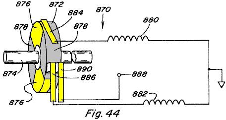
In Fig.44 a system 870 including member 872 mounted on rotating shaft 874 is provided, with the left side of member 872 being alternately conductive at 876 and non-conductive at 878. Coils 880 and 882 are connected to respective brushes 884 and 886 which are positioned to contact member 872 during each rotation of the shaft. Member 872 is connected through brush 890 to power supply 888. Thus, coils 880 and 882 will alternately be energised and de-energised as the respective brushes thereof contact the conductive and non-conductive portions of member 872.
Any of such circuit means, variations thereof, or other circuit means may be used to provide the timed energisation of the control coils in the various embodiments of the present invention.
From the preceding description of the illustrated embodiments, it is evident that the objects of the invention are attained. Although the invention has been described and illustrated in detail, it is to be clearly understood that the same is intended by way of illustration and example only and is not to be taken by way of limitation.
For example, although the magnetic flux control techniques of the present invention have been discussed as applicable mainly to various motive applications, such magnetic flux control techniques are also useful in static applications.
Power
Conversion
Referring to Figs.45A-45C there is shown the permanent magnet device 900 of Figs.45A-45C which has two magnetic flux paths provided by rectangular pole piece 902 which includes upper portion 904 and lower portion 906 each positioned against a respective pole face of permanent magnet 910. Unlike the device of Figs.7-9, fall away armatures are not provided. Instead, fixed armatures in the form of integral pole piece portions 912 and 914 extend from upper portion 904 to lower portion 906 completing the two flux paths in a permanent manner. Control coils 916, 918 are provided along one flux path and control coils 920, 922 are provided along the other flux path, such control coils acting as primary windings in device 900. One coil 924 is positioned around pole piece portion 912 and another coil 926 is positioned around pole piece portion 914, such coils 924, 926 acting as secondary windings in device 900.

In Fig.45A no coils are energised and the permanent magnet magnetic flux splits evenly between paths 930 and 932, coupling with both coil 924 and coil 926.
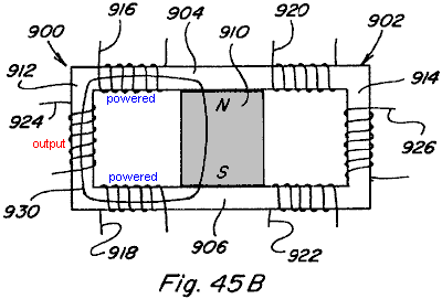
In Fig.45B coils 916, 918 are energised in a permanent magnet magnetic flux aiding manner so as to couple with all the magnetic flux of permanent magnet 910. All magnetic flux flows along path 930 as shown and thus couples with coil 924.
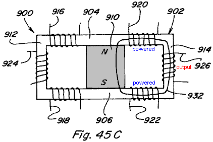
In Fig.45C coils 920, 922 are energised in a permanent magnet magnetic flux aiding manner such that all magnetic flux traverses path 932 and couples with coil 926. By continuously alternately energising and de-energising coils 916, 918 and 920, 922 in such a manner energy conversion is achieved due to the coupling with coils 924 and 926. The magnetic flux in the integral pole piece portions 912 and 914, and thus the flux coupling with respective coils 924 and 926, varies by a factor of twice the amount of magnetic flux generated by energising coils 916, 918 and 920, 922.
The construction shown in Fig.45A and Fig.45X are similar to the construction shown in Fig.7 and Fig.47. The difference in both cases relates to replacing the two flux paths and armatures with one continues flux path. The arrangement in Fig.7 has one permanent magnet and four coils and the arrangement in Fig.47 has two permanent magnets and two coils. Although the physical aspects of the two arrangements and the details of the flux control vary, the control method for varying the permanent magnets flux are similar and will be described simultaneously and only differences will be pointed out.
With continuous flux paths the static flux from the permanent magnet or magnets is useless. However, if the static flux of the permanent magnet confined to the flux paths were modified to be time varying it would have utility for electromagnetic induction devices for power conversion like transformers and power inverters. However, the same basic method for controlling the flux of a permanent magnet to provide linear and rotary motion can also be applied to time varying the static flux from the permanent magnet. The construction shown in Fig.45X utilises four control coils and a single permanent magnet while the construction shown in Fig.45A uses two control coils and two permanent magnets. The flux that would normally be supplied by a primary winding is supplied by the static flux of the permanent magnet or magnets and the control coils convert this static flux into a time varying flux in a novel way. Both arrangements use two secondary coils, the secondary coils are placed in the region of the continuous flux path that would be occupied by an armature or rotor in the linear or rotary arrangements. The regions of the flux paths that perform work are the same in all cases.
In all cases the control coils can either be wired in series or parallel and the secondary coils can be either wound in series or parallel. More than one secondary coil or secondary coils with multiple taps can be placed in the working regions and further multiple flux paths can be utilised with one or more secondary coils placed in each of the working regions. This is made obvious by the disclosures of the linear and rotary devices herein and based on the fact that the working regions of the flux paths are identical.
Fig.45X and Fig.45A also show the paths of the static flux of the permanent magnet or magnets when no current is flowing in the control coils. In the arrangement shown in Fig.45X the flux from the single permanent magnet divides between the two working areas of the flux path. In the arrangement of Fig.45A all of the flux of one of the permanent magnets passes through one of the working regions and all of the flux of the second permanent magnet passes through the other working region. Each of the working regions in both cases are occupied by secondary coils.
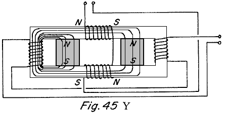
Fig.45Y and Fig.45B show the control coils energised with the polarity shown with respect to the polarity of the permanent magnet or magnets included. In Fig.45Y the opposing coil, blocks the passage of flux from the permanent magnet, and the aiding coil couples with the flux of the permanent magnet and therefore all of the flux of the permanent magnet passes through one working region as shown. In Fig.45B the opposing side of the coil blocks the passage of flux from the permanent magnet on the opposing side of the coil and the aiding side of the coil couples with the flux of the other permanent magnet and therefore all of the flux of both the permanent magnets passes through the working region as shown.
Fig.45Z and Fig.45C show the control coils energised with a polarity opposite of that shown in Fig.45Y and Fig.45B. The same action occurs and results in all of the permanent magnet or magnets path flux passing through the opposite working regions.
By alternating the polarity of the control coils during one cycle, one working region experiences an increasing flux and the opposite region experiences a decreasing flux and during the next cycle the opposite occurs. This results in the induction of a voltage in the secondary coils that is decided by the magnitude of the change in flux in the working region and the time in which this change occurs. The novelty of this discovery is that the primary flux inducing the voltage in the secondary coils is supplied by the permanent magnet or magnets and is far greater than the flux supplied by the control coils.
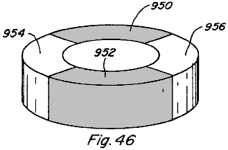
Further, in the rotary motion devices of Fig.31 and Fig.34, it is not necessary that respective rotor members 702 and 744 be formed of permanent magnets. Each could take the form shown in Fig.46 where sections 950 and 952 are formed of magnetic material such as soft iron and sections 954 and 956 are formed by a non-magnetic filler material.
Fig.47 and Fig.48 show another embodiment 1000 of the subject device. The embodiment 1000 includes two spaced permanent magnets 1002 and 1004 each of which has its north pole adjacent to the upper surface and its south pole adjacent to the lower surface. A magnetisable bridging member 1006 extends across and makes contact with the north magnetic poles of the magnets 1002 and 1004 and another magnetisable bridging member 1008 makes contact with the south magnetic poles of the two permanent magnets 1002 and 1004.
The members 1006 and 1008 extend slightly beyond the opposite sides of the respective permanent magnets 1002 and 1004 and a pair of spaced armature members 1010 and 1012 are positioned to move into and out of engagement with the ends of the members 1006 and 1008. Coils 1014 and 1016 are mounted respectively on the members 1006 and 1008 in the space between the permanent magnets 1002 and 1004, and the armatures 1010 and 1012 are shown connected together by a rod 1018 which enables them to move backwards and forwards into engagement with the respective members 1006 and 1008 when different voltages are applied to the respective coils 1014 and 1016.
In Fig.47, the coils 1014 and 1016 are energised as shown with the coil 1014 having its north magnetic end to the left and its south magnetic end to the right and the opposite is true of the coil 1016. In Fig.48, the voltage applied to the respective coils 1014 and 1016 is reversed so that the polarity of the left end of coil 1014 is south and the polarity of the opposite end of the same coil 1014 is a north magnetic pole. The reverse is true of the coil 1016. In Fig.47 and Fig.48 it should be noted that the relationship of aiding and opposing is indicated on the figures to indicate the relationship when the coils are energised. For example, in Fig.47 when the coils are energised as shown the relationship is opposing for the permanent magnet 1002 and is aiding with respect to the permanent magnet 1004. The reverse is true when the voltage on the coils is reversed as shown in Fig.48. The movement of the armature is therefore controlled by the proper timing of the voltage on these coils. The same principles can be applied to produce rotating movement as shown in Fig.42.
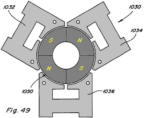
Fig.49 shows another embodiment 1030 of the subject invention using principles similar to those described in connection with Fig.47 and Fig.48. The embodiment 1030 includes a plurality, three being shown, of stationary members 1032, 1034 and 1036.
The details of these members are better shown in Fig.50 which shows the details of the member 1036. This member includes a pair of permanent magnets 1038 and 1040, each of which has magnetisable members mounted adjacent to it’s opposite sides, as in the previous construction. The members 1042 and 1044 also have coils 1046 and 1048, respectively, and the coils are energised as described in connection with Fig.47 and Fig.48 to produce aiding and opposing magnetism. The construction shown in Fig.49 may have three stator portions as shown or it may have more stator portions as desired. The rotor 1050 is positioned in the space between the members 1032, 1034 and 1036 and includes a permanent magnet portion part of which has its north magnetic pole on the surface as shown and the other parts has its south magnetic pole in the same surface as shown. The permanent magnets 1038 and 1040 on the stators interact with the permanent magnets on the rotor to produce the rotating motion and is controlled by the energising of the coils.
Other applications and advantages of the devices and methods of the present invention exist and various modifications are possible, and therefore the present invention is not intended to be limited to the specific examples disclosed herein. Accordingly, the spirit and scope of the invention are to be limited only by the terms of the appended claims.
DAN DAVIDSON: ACOUSTIC-MAGNETIC POWER GENERATOR
US Patent 5,568,005
22nd October 1996
Inventor: Dan A. Davidson
ACOUSTIC-MAGNETIC POWER GENERATOR
Please note
that this is a re-worded excerpt from this patent. If the content interests you, then you should
obtain a full copy via the www.freepatentsonline.com web site. This patent describes an electrical device
very similar to the MEG device, capable of powering itself while powering
additional external items of equipment.
ABSTRACT
The Acoustic Magnetic Field Power Generator uses an acoustic signal focused into a permanent magnet to stimulate the nuclear structure of the magnet to cause the magnetic field of the permanent magnet to move or oscillate. This effect can be used to tap power from the oscillating magnetic field by putting a coil of wire in the oscillating field. When an alternating current signal generator is connected simultaneously to an acoustic transducer and a stimulating coil; whereby, both the acoustic transducer and the stimulating coil are located within the magnetic field of the magnet, the acoustic signal enhances the stimulating effect to the permanent magnet transformer. The acoustic transducer can be any acoustic generation device such as a piezoelectric, magnetostrictive, or other acoustic transducer. The combined effect of the acoustic signal and the stimulating coil increases the efficiency of permanent magnet induction transformers.
BACKGROUND OF THE INVENTION
The present invention relates to a solid state electrical generator having no moving parts. More particularly, the invention makes use of a new method of stimulating the nuclear material of a permanent magnet so that the electronic structure of the atom will vibrate and thus cause the magnetic field of the permanent magnet to oscillate. It is a well-known fact that an oscillating magnetic field will induce electrical current in a coil as was discovered by Michael Faraday in the last century. What is new in this invention, is the discovery of the ability of an acoustic field to stimulate the nuclear structure of a material to cause the electrons to wobble under the influence of the acoustic field. If the material is magnetic or temporarily magnetised by an external magnetic field then the magnetic field will vibrate under the stimulus of the acoustic field. If this effect is combined with a coil which is simultaneously stimulating the magnet then the efficiency of stimulating the permanent magnet's field is enhanced. If a pickup coil is placed in the oscillating magnetic field so as to create an induction transformer then the combination of the acoustic and magnetic stimulation will enhance the efficiency of the induction transformer.
The most relevant prior art known to the inventor comprises U.S. Pat. No. 4,904,926 (1990) to Mario Pasichinsky, entitled Magnet Motion Electrical Generator; and U.S. Pat. No. 4,077,001 (1978) to Frank Richardson, entitled Electromagnetic Converter With Stationary Variable-Reluctance Members; and U.S. Pat. No. 4,006,401 (1977) to de Rivas, entitled Electromagnetic Generator.
The above
references to Pasichinsky, Richardson, and de Rivas, all use inductive methods
to stimulate the motion of a permanent magnetic field. In the de Rivas invention, ‘Electromagnetic
Generator’, the flux of the permanent magnet is "alternated by
switching" using inductive coupling.
In the
Other prior art relevant to the invention are U.S. Pat. No. 2,101,272 (1937) to H. J. Scott, entitled Combined Magnetostriction and Piezoelectric Selective Device; and U.S. Pat. No. 2,636,135 (1953) to R. L. Peek, Jr. entitled Stress Coupled Core and Crystal Transformer, and U.S. Pat. No. 2,834,943 (1958) to R. O. Grisdale, etal entitled Mechanically Coupled Electromechanical and Magnetomechanical Transducers, and U.S. Pat. No. 3,246,287 (1966) to H. F. Benson entitled Piezoelectric Transformer, and U.S. Pat. No. 3,261,339 (1966) to H. P. Quinn entitled Magnetostrictive Transformer, and U.S. Pat. No. 3,274,406 (1966) to H. S. Sommers, Jr. entitled Acoustic Electromagnetic Device, and U.S. Pat. No. 3,309,628 (1967) to F. A. Olson entitled YIG Variable Acoustic Delay Line, and U.S. Pat. No. 3,457,463 (1969) to L. Balamuth entitled Method and Apparatus for Generating Electric Currents of Small Magnitude, and U.S. Pat. No. 4,443,731 (1984) to Butler et al. entitled Hybrid Piezoelectric and Magnetostrictive Acoustic Wave Transducer, and U.S. Pat. No. 4,552,071 (1985) to R. B. Thompson entitled Method and Apparatus for Measuring Stress.
The reference to Peek cited above, takes advantage of the difference in operation of piezoelectric and magnetostrictive crystals to produce a response in one when stimulated by the other. The Peek patent does not use an acoustic wave to stimulate a permanent magnet as in the present invention.
The reference to Sommers cited above, is a transducer which uses a conductive bar or tube, which supports relatively slow helicon waves, placed next to a piezoelectric or magnetostrictive crystal. The transducer is designed in such a way as to either enhance the acoustic wave or the electric wave by interaction of the two materials. The Sommers patent does not use an acoustic wave to stimulate a permanent magnet to enhance to oscillation of the magnetic field as the present invention does.
The reference to Balmuth cited above, uses mechanically resonant reeds, rods, or chambers which are coupled to transducers that are piezoelectric, magnetostrictive, or transistorised. The electrical output of the transducers stimulates an electrical circuit when the resonator receives acoustic energy and again does not use an acoustic wave to stimulate a permanent magnet to enhance to oscillation of the magnetic field as the present invention does.
The reference to Olson cited above, uses an acoustically responsive material such as a piezoelectric or a magnetostrictive to act as a delay line for microwave signals and again does not use an acoustic wave to stimulate a permanent magnet to enhance to oscillation of the magnetic field as the present invention does.
The references
to Benson, Quinn, Grisdale, Scott, and
The reference to Thompson cited above, uses a permanent magnetic transducer to induce eddy currents in metal which is in the field of the transducer or uses moving eddy currents in a piece of metal to stimulate a magnetic field. The induction of the eddy currents is the result of an oscillating magnetic field generated in the transducer.
None of the references cited above, use an acoustic wave to stimulate the atoms of a permanent magnet and hence are not related to this invention.
SUMMARY OF
THE INVENTION
An object of this invention is to provide a power generator with no moving parts.
Another object of this invention is to use an acoustic field to stimulate the nuclear level of the magnetic material and provide a method of oscillating the magnetic field of permanent magnets.
Another object of this invention is to provide a simple method of generating electrical energy by including a piezoelectric transducer which is used to vibrate the magnetic field of a permanent magnet. When the nucleus of the atom is vibrated by the piezoelectric, it in turn, vibrates the electronic structure of all the atoms. Since the electronic structure is the basis of the magnetic field of the magnet then the entire magnetic field of the magnet is vibrated when the electronic structure is vibrated. Coils placed in the vibrating magnetic field will have voltage and current induced in them.
It is a well established fact, that when the magnetic field of a permanent magnet is vibrated, it is possible to generate an alternating current in a coil winding placed within the vibrating magnetic field. What is unique about this invention, is to increase the efficiency of permanent magnet transformers by using acoustic stimulation from piezoelectrics to further stimulate the permanent magnet so as to add to the inductive effects of permanent magnet transformers. This invention does this by stimulating the permanent magnet cores of permanent magnet transformers with an acoustic field generated by a piezoelectric or other acoustically active generator which is vibrated at the same frequency as the electrical induction of the permanent magnet transformers.
BRIEF DESCRIPTION OF THE DRAWINGS
FIG.1 illustrates a frequency signal generator attached to and driving a piezoelectric transducer which is in the acoustic proximity of a bar type of permanent magnet with a output coil placed within the magnetic field of the permanent magnet.
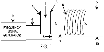
Fig.2 illustrates a frequency signal generator attached to and driving a piezoelectric transducer which is in the acoustic proximity of a torroidal type of permanent magnet with an output coil wrapped around the torroidal permanent magnet.
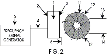
Fig.3 illustrates a frequency signal generator attached to and driving a piezoelectric transducer which is in the acoustic proximity of a torroidal type of permanent magnet transformer and the signal generator is also driving the input coil of the torroidal permanent magnet transformer.
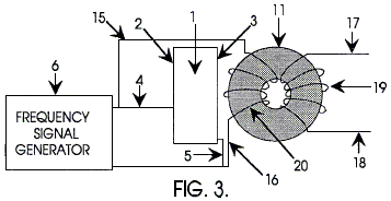
Fig.4 illustrates a frequency signal generator attached to and driving two torroidal core permanent magnet transformers as well as an acoustic transducer that is in acoustic proximity of the torroidal cores.

DETAILED DESCRIPTION OF THE INVENTION
In Fig.1, a frequency signal generator 6 is connected to a piezoelectric transducer 1 via wires 4 and 5 connected to the electrode surfaces of the piezoelectric transducer 2 and 3 respectively. The piezoelectric transducer 1 is made from a high dielectric material such as barium titanate or lead zirconate titanate or any other acoustic transducer material suitable for sonic and ultrasonic generators. The piezoelectric transducer 1 is placed in close proximity to the permanent magnet 7 such that the acoustic field of the piezoelectric transducer 1 can radiate into the permanent magnet material. A permanent magnet transformer shown as coil 8 is positioned in the magnetic field of the permanent magnet 7. When the piezoelectric transducer 1 is stimulated by the frequency generator 6 then a voltage and current is generated between the output leads 9 and 10 of the permanent magnet transformer.
Another embodiment of this invention is shown in Fig.2. which is similar to Fig.1, with a similar frequency signal generator 6 connected to a piezoelectric material 1 via wires 4 and 5 connected to the electrode surfaces of the piezoelectric transducer 2 and 3. The piezoelectric transducer 1 is as defined above, that is to say that it is constructed from a material suitable for sonic and ultrasonic generators. The piezoelectric transducer 1 is placed in close proximity to the permanent magnet 11 so that the acoustic field of the piezoelectric transducer 1 can radiate into the permanent magnet material. A permanent magnet transformer shown as coil 12 is placed in the magnetic field of the permanent magnet 11. When the piezoelectric transducer 1 is stimulated by the frequency generator 6 then a voltage and current is generated between the output leads 13 and 14 of the above defined magnetic transformer.
Fig.3 is similar to Fig.1 and Fig.2 with a frequency signal generator 6 connected to a piezoelectric transducer 1 via wires 4 and 5 connected to the electrode surfaces 2 and 3 of the piezoelectric transducer. The piezoelectric transducer 1 is as defined in the descriptions above. The signal generator 6 is also connected to the input coil 20 of the permanent magnet transformer defined by the torroidal permanent magnet core 11, input coil 20 and output coil 19. The piezoelectric transducer 1 is placed in close proximity to the permanent magnet 11 so that the acoustic field of the piezoelectric transducer 1 can radiate into the permanent magnet material. The magnetic transformer defined by 11, 19, and 20 is in the magnetic field of the permanent magnet 11 and is connected to the frequency signal generator 6 via wires 15 and 16. The frequency generator 6 stimulates the piezoelectric transducer 1 which stimulates the permanent magnet transformer via the acoustic field and at the same time the signal generator also stimulates the coil electromagnetically. A voltage and current is generated at the output coil 19 and power can be taken from the output wires 17 and 18 of the magnetic transformer.
A further embodiment of this invention, shown in Fig.4, is a frequency signal generator 6 driving a pair of permanent magnet transformers defined by 26, 35, 27 and 25, 36, 28 respectively, also driving a piezoelectric transducer 1. The piezoelectric transducer is as described above. The signal generator is connected via input wires 23 and 24 to the input coil 26 of the permanent magnet transformer on the left and to the input coil 25 of the transformer on the right respectively. The other input wire 38 of the left permanent magnet transformer is connected to the remaining input wire 39 of the right magnetic transformer. The output of the signal generator in also connected to the piezoelectric transducer 1 via connections 21 and 22 to the connector surface of the piezoelectric 33 and 34 respectively. The output of the permanent magnet transformer on the left is connected to a load 40 via wire 30 and the output of the permanent magnet transformer on the right is connected to the load via wire 29. The remaining output wires 31 and 32 of the left and right permanent magnet transformers are also connected to the load. The load 40 can be anything such as a motor or electrical lights or any appliance.
This invention is not limited to the 4 different versions of the invention shown in Figs. 1, 2, 3, and 4 as there are any number of cascading and electrical hook-up techniques that can be accomplished to amplify power and to take advantage of the acoustic influence of the piezoelectric upon the magnetic material. Similarly, this invention is not limited to the torroidal core configuration as there can be many types of permanent magnet transformers with any number of magnetic core and coil configurations that can be enhanced with acoustic stimulation depending on power and output requirements according to the rules of electronics and those familiar with the state of the art in permanent magnet power transformers.
JOHN BEDINI: BATTERY CHARGER
DEVICE AND METHOD FOR UTILISING A MONOPOLE
MOTOR
TO CREATE BACK-EMF TO CHARGE BATTERIES
Please note
that this is a re-worded excerpt from this patent. It describes a self-contained device which
can charge an external battery or battery bank.
ABSTRACT
A back EMF monopole motor and method using a rotor containing magnets all of the same polarity and in a monopole condition when in momentary apposition with a magnetised pole piece of a stator having the same polarity, the stator being comprised of a coil with three windings: a power-coil winding, a trigger-coil winding, and a recovery-coil winding. The back EMF energy is rectified using a high voltage bridge, which transfers the back EMF energy to a high voltage capacitor for storage in a recovery battery. The stored energy can then be discharged across the recovery battery through the means of a contact rotor switch for further storage.
DESCRIPTION
Technical Field:
The invention relates generally to the capturing of available electromagnetic energy using a device and method for creating an electromagnetic force (‘EMF’) and then using the available stored energy for recycling into the system as stored energy. The method of creating back EMF is the result of coupling/uncoupling a coil to a voltage source.
Background:
The operation of present day normal magnetic motors, has the rotor pole attracting the stator pole, resulting in the generation of mechanical power from the magnets to the rotor and flywheel. During this phase, energy flows from the magnetics to the rotor/flywheel and is stored as kinetic energy in the increased rotation. A rotor pole leaving a stator pole and creating a condition of "drag" results in power having to be put back into the magnetic section by the rotor and flywheel to forcibly overcome the drag. In a perfect, friction-free motor, the net force field is therefore referred to as "most conservative". A most conservative EMF motor has maximum efficiency. Without extra energy continually fed to the motor, no net work can be done by the magnetic field, since half the time the magnetic field adds energy to the load (the rotor and flywheel) and the other half of the time it subtracts energy from the load (the rotor and flywheel). Therefore, the total net energy output is zero in any such rotary process without additional energy input. To use a present day magnetic motor, continuous energy must be fed to the motor to overcome drag and to power the motor and its load.
Motors and generators presently in use, all use such conservative fields and therefore, have internal losses. Hence, it is necessary to continually input all of the energy that the motor outputs to the load, plus more energy to cover losses inside the motor itself. EMF motors are rated for efficiency and performance by how much energy "input" into the motor actually results in "output" energy to the load. Normally, the Coefficient of Performance (‘COP’) rating is used as a measure of efficiency. The COP is the actual output energy going into the load and powering it, divided by the energy that must be input into the device with its motor/load combination. If there were zero internal losses in a motor, that "perfect" motor would have a COP equal to 1.0. That is, all energy input into the motor would be output by the motor directly into the load, and none of the input energy would be lost or dissipated in the motor itself.
In magnetic motor generators presently in use, however, due to friction and design flaws, there are always internal losses and inefficiencies. Some of the energy input into the motor is dissipated in these internal losses. As a consequence, the energy that gets to the load is always less than the input energy. So a standard motor operates with a COP of less than 1.0, which is expressed as COP<1.0. An inefficient motor may have a COP of 0.4 or 0.45, while a specially designed and highly efficient motor may have a COP of 0.85.
The conservative field inside of a motor itself is divided into two phases. Producing a conservative field involves net symmetry between the "power out" phase from the magnetics to the rotor/flywheel and the "power back in" phase from the rotor/flywheel back to the magnetics. That is, the two flows of energy are identical in magnitude but opposite in direction. Each phase alone is said to be "asymmetrical", that is, it either has: 1) a net energy flow out to the rotor/flywheel; or 2) a net energy flow back into the magnetics from the rotor/flywheel. In simplified terms, it is referred to as "power out" and "power back in" phases with respect to the motor magnetics.
For the power-out phase, energy is derived from the EMF existing between the stator pole and incoming rotor pole in an attraction mode. In this phase, the rotary motion (angular momentum and kinetic energy) of the rotor and flywheel is increased. In short, power is added to the rotor/flywheel (and thus to the load) from the fields between stator pole and rotor pole (the electromagnetic aspects of the system).
For the "power back in" phase, energy must be fed back into the magnetics from the rotor and flywheel (and the load) to overcome the drag forces existing between stator pole and outgoing rotor pole. In this phase, energy is returned to the internal magnetic system from the rotary motion of the rotor and flywheel (the angular momentum, which is the rotational energy multiplied by time). As is well known in physics, a rotor/flywheel's angular momentum provides a convenient way to store energy with the spinning rotor/flywheel mass acting as an energy reservoir.
Most present day conventional magnetic motors use various methods for overcoming and partially reversing back EMF. Back EMF may be defined as the return pulse from the coil out of phase and is the result of re-gauging, which is the process of reversing the magnetics polarity, that is, form North to South, etc. The back EMF is shorted out and the rotor is attracted back in, therefore eliminating drag. This can be accomplished by pouring more energy in, which overpowers the back EMF, thereby producing a forward EMF in that region. The energy required for this method is furnished by the operator.
It is well known that changing the voltage alone creates a back EMF and requires no work. This is because to change the potential energy does not require changing the form of that potential energy, but only its magnitude. Work is the changing of the form of energy. Therefore, as long as the form of the potential energy is not changed, the magnitude can be changed without having to perform work in the process. The motor of the present invention takes advantage of this permissible operation to create back EMF asymmetrically, and thereby change its own usable available potential energy.
In an electric power system, the potential (voltage) is changed by inputting energy to do work on the internal charges of the generator or battery. This potential energy is expended within the generator (or battery) to force the internal charges apart, forming a source dipole. Then the external closed circuit system connected to that source dipole ineptly pumps the spent electrons in the ground line back through the back EMF of the source dipole, thereby scattering the charges and killing the dipole. This shuts off the energy flow from the source dipole to the external circuit. As a consequence of this conventional method, it is a requirement to input and replace additional energy to again restore the dipole. The circuits currently utilised in most electrical generators have been designed to keep on destroying the energy flow by continually scattering all of the dipole charges and terminating the dipole. Therefore, it is necessary to keep on inputting energy to the generator to keep restoring its source dipole.
A search of prior art failed to reveal any monopole motor devices and methods that recycle available energy from back EMF to charge a battery or provide electrical energy for other uses as described in the present invention. However, the following prior art patents were reviewed:
SUMMARY OF THE INVENTION
An aspect of the device and method of the present invention is a new monopole electromagnetic motor that captures back EMF energy. The captured back EMF energy may be used to charge or store electrical energy in a recovery battery. The amount of energy recoverable, as expressed in watts, is dependent upon the configuration, circuitry, switching elements and the number and size of stators, rotors, magnets and coils which comprise the motor.
The motor uses a small amount of energy from a primary battery to "trigger" a larger input of available energy by supplying back EMF, thus increasing the potential energy of the system. The system then utilises this available potential energy to reduce, or reverse, the back EMF, thereby increasing the efficiency of the motor and, therefore, the COP.
If the energy in phase 1 (the power-out phase) is increased by additional available energy in the electromagnetics themselves, then the energy in phase 1 can be made greater than the energy in phase 2 (the power-back-in phase) without the operator furnishing the energy utilised. This produces a non-conservative nett field. Nett power can then be taken from the rotating stator and flywheel, because the available energy added into the stator and flywheel by the additional effects, is transformed by the rotor/flywheel into excess angular momentum and stored as such. Angular momentum is conserved at all times, but now, some of the angular momentum added to the flywheel, is evoked by additional effects in the electromagnetics, rather than being furnished by the operator.
That is, the motor is designed to deliberately create a back EMF itself, and thus increase its potential energy, thereby retaining each extra force for a period of time and applying it to increase the angular momentum and kinetic energy of the rotor and flywheel. Specifically, this back EMF energy with its nett force is deliberately applied in the motor of the present invention to overcome and even reverse the conventional drag-back (the back EMF). Hence, less energy needs to be taken from the rotor and flywheel to overcome the reduced back EMF, and in the ideal case, none is required since the back EMF has been overpowered and converted to forward EMF by the back EMF energy and force. In the motor, the conventional drag section of the magnetics becomes a forward-EMF section and now adds energy to the rotor/flywheel instead of reducing it. The important feature is that the operator only pays for the small amount of energy necessary to trigger the back EMF from the primary battery, and does not have to furnish the much larger back EMF energy itself.
Thus, when the desired energy in phase 1 (the power-out phase) is made greater than the undesired drag energy in phase 2, then part of the output power normally taken from the rotor and flywheel by the fields in phase 2, is not required. Hence, in comparison to a system without special back EMF mechanisms, additional power is available from the rotor/flywheel. The rotor therefore maintains additional angular momentum and kinetic energy, compared to a system which does not produce back EMF itself. Consequently, the excess angular momentum retained by the rotor and flywheel can be utilised as additional shaft power to power an external load.
In this motor, several known processes and methods are utilised. These allow the motor to operate periodically as an open dissipative system (receiving available excess energy from back EMF) far from thermodynamic equilibrium, whereby it produces and receives its excess energy from a known external source.
A method is utilised to temporarily produce a much larger source of available external energy around an energised coil. Design features of this new motor provide a device and method that can immediately produce a second increase in that energy concurrently as the energy flow is reversed. Therefore, the motor is capable of producing two asymmetrical back EMFs, one after the other, of the energy within a single coil, which dramatically increases the energy available and causes that available excess energy to then enter the circuit as impulses which are collected and utilised.
The motor utilises this available excess back EMF energy to overcome and even reverse the drag EMF between stator pole and rotor pole, while furnishing only a small trigger pulse of energy from a primary battery necessary to control and activate the direction of the back EMF energy flow.
By using a number of such dual asymmetrical self back EMFs for every revolution of the rotor, the rotor and flywheel collectively focus all the excess impulsive inputs into increased angular momentum (expressed as energy multiplied by time), shaft torque, and shaft power.
Further, some of the excess energy deliberately generated in the coil by the utilisation of the dual process manifests in the form of excess electrical energy in the circuit and can be utilised to charge a recovery battery or batteries. The excess energy can also be used to power electrical loads or to power the rotor and flywheel, with the rotor/flywheel also furnishing shaft horsepower for powering mechanical loads.
The motor utilises a means to furnish the relatively small amount of energy from a primary battery to initiate the impulsive asymmetrical self back EMF actions. Then part of the available excess electrical power drawn off from back EMF created energy is utilised to charge a recovery battery with dramatically increased over-voltage pulses.
Design features of this monopole motor utilise one magnetic pole of each rotor and stator magnet. The number of impulsive self-back EMF in a single rotation of the rotor is doubled. Advanced designs can increase the number of self-back EMFs in a single rotor rotation with the result that there is an increase in the number of impulses per rotation, which increase the power output of this new motor.
The sharp voltage spike produced in the coil of this monopole motor by the rapidly collapsing field in the back EMF coil is connected to a recovery battery(s) in charge mode and to an external electrical load. The nett result is that the coil asymmetrically creates back EMF itself in a manner which adds available energy and impulse to the circuit. The available energy collected in the coil is used to reverse the back-EMF phase of the stator-rotor fields to a forward EMF condition, with the impulses adding acceleration and angular momentum to the rotor and flywheel. The available back EMF energy collected in the coil is used to charge a battery. Loads can then be driven by the battery.
A device and method in which the monopole motor alters the reaction cross section of the coils in the circuit, which briefly changes the reaction cross section of the coil in which it is invoked. Thus, since this new motor uses only a small amount of current in the form of a triggering pulse, it is able to evoke and control the immediate change of the coil's reaction cross section to this normally wasted energy-flow component. As a result, the motor captures and directs some of this usually wasted available environmental energy, collecting the available excess energy in the coil and then releasing it for use in the motor. Through timing and switching, the innovative gate design of this new motor directs the available excess energy so that it overcomes and reverses the return EMF of the rotor-stator pole combination during what would normally be the back EMF and demonstrates the creation of the second back EMF of the system. Now, instead of an "equal retardation" force being produced in the back EMF region, a forward EMF is produced which adds to the rotor/flywheel energy, rather than subtracting from it. In short, it further accelerates the rotor/flywheel.
This results in a non-conservative magnetic field along the rotor's path. The line integral of the field around that path (i.e., the net work on the rotor/flywheel to increase its energy and angular momentum) is not zero but a significant amount. Hence, the creation of an asymmetrical back EMF impulse magnetic motor:
1) Takes its available excess energy from a known external source, the huge usually non-intercepted portion of the energy flow around the coil;
2) Further increases the source dipolarity by this back EMF energy; and
3) Produces available excess energy flow directly from the source dipole's increased broken symmetry in its fierce energy exchange with the local vacuum.
By operating as an open dissipative system, not in thermodynamic equilibrium with the active vacuum, the system can permissibly receive available energy from a known environmental source and then output this energy to a load. As an open dissipative system not in thermodynamic equilibrium, this new and unique monopole motor can tap in on back EMF to energise itself, loads and losses simultaneously, fully complying with known laws of physics and thermodynamics.
BRIEF DESCRIPTION OF THE DRAWINGS
Fig.1 is a perspective side view of a monopole back EMF motor with a single stator and a single rotor.
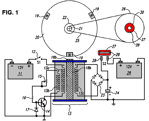
Fig.2 is a perspective top view of a monopole back EMF motor with a single stator and a single rotor.
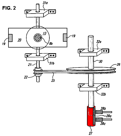
Fig.3 is a block diagram demonstrating the circuitry for a monopole back EMF motor.
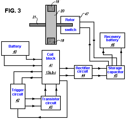 .
.
DETAILED DESCRIPTION OF THE INVENTION
An embodiment of the present invention is a device and method for a monopole back EMF electromagnetic motor. As described in the Summary of the Invention, this monopole motor conforms to all applicable electrodynamic laws of physics and is in harmony with the law of the conservation of energy, the laws of electromagnetism and other related natural laws of physics.
The monopole back EMF electromagnetic motor comprises a combination of elements and circuitry to capture available energy (back EMF) in a recovery element, such as a capacitor, from output coils. The available stored energy in the recovery element is used to charge a recovery battery.
As a starting point, an arbitrary method in describing this device will be employed, namely, the flow of electrical energy and mechanical forces will be tracked from the energy's inception at the primary battery to its final storage in the recovery battery.
Fig.1 is a perspective side view of the monopole motor according to an embodiment of the invention. As shown in Fig.1, electrical energy from primary battery 11 periodically flows through power switch 12 and through power-coil wiring 13a. In one embodiment, power switch 12 is merely an On-Off mechanical switch and is not electronic. However, the switch 12 may be a solid-state switching circuit, a magnetic Reed switch, a commutator, an optical switch, a Hall-effect switch, or any other conventional transistorised or mechanical switch. Coil 13 is comprised of three windings: power-coil winding 13a, trigger-coil winding 13b, and recovery-coil winding 13c. However, the number of windings can be more or fewer than three, depending upon the size of the coil 13, size of the motor and the amount of available energy to be captured, stored and used, as measured in watts. Electrical energy then periodically flows from power-coil winding 13a and through transistor 14.
Trigger energy also periodically flows through variable resistor 15 and resistor 16. Clamping diode 17 clamps the reverse base-emitter voltage of transistor switch 14 at a safe reverse-bias level that does not damage the transistor. Energy flows to stator 18a and pole piece 18b, an extension of stator 18a. Pole piece 18b is electrically magnetised only when transistor switch 14 is on and maintains the same polarity as the rotor poles 19 - North pole in this instance - when electrically magnetised. The North rotor poles 19a, 19b and 19c, which are attached to rotor 20, come in momentary apposition with pole piece 18b creating a momentary monopole interface. The poles 19a,b,c, which are actually permanent magnets with their North poles facing outward from the rotor 20, maintain the same polarity when in momentary alignment with pole piece 18b.
Rotor 20 is attached to rotor shaft 21, which has drive pulley 22. Attached to rotor shaft 21 are rotor-shaft bearing blocks 31a and 31b, as seen in Fig.2. As rotor 20 begins to rotate, the poles 19a,b,c respectively comes into alignment with magnetised pole piece 18b in a momentary monopole interface with energy flowing through diode bridge rectifier 23 and capacitor 24. The number of capacitors may be of a wide range, depending upon the amount of energy to be temporarily stored before being expelled or flash charged into recovery battery 29. Timing belt 25 connects drive pulley 22 on timing shaft 21 to timing wheel 26. Attached to timing wheel 26 is contact rotor 27, a copper insulated switch that upon rotation, comes in contact with brushes on mechanical switch 28. The means for counting the number of rotor revolutions may be a timing gear or a timing belt. Finally, the available energy derived from the back EMF that is stored in capacitor 24 is then discharged and stored in recovery battery 29.
Fig.2 is a mechanical perspective top view of the monopole motor of the instant invention without electrical circuitry. Stator 18a consists of coil 13, which is comprised of three separate coil windings: power-coil winding 13a, trigger-coil winding 13b and recovery-coil winding 13c. Pole piece 18b is at the end of stator 18a. As rotor 20, (which is attached to rotor shaft 21) rotates, each pole 19 respectively comes in a momentary monopole interface with pole piece 18b. The polarity of pole piece 18b is constant when electrically magnetised. Rotor shaft 21 has rotor shaft bearing blocks 31a,b attached to it for stabilisation of rotor shaft 21. Attached to rotor shaft 21 is drive pulley 22 with timing belt 25 engaged with it. Another means for timing may be a timing gear. Timing belt 25 engages with timing wheel 26 at its other end. Timing wheel 26 is attached to timing shaft 30. Shaft 30 is stabilised with timing shaft bearing blocks 32a,b. Attached to one end of timing shaft 30 is contact rotor 27 with brush 28a, which, upon rotation of the timing shaft, comes into momentary contact with brushes 28b,c.
Fig.3 is a block diagram detailing the circuitry of the monopole motor. Block 40 represents primary battery 11 with energy flowing to coil block 41, which represents coil windings 13a,b,c. From coil block 41 energy flows into three directions: to trigger-circuit block 42, transistor-circuit block 43, and rectifier-circuit block 44. Energy flows from rectifier-block 44 to storage-capacitor block 45 with energy flowing from block 45 to both recovery-battery block 46 and rotor-switch block 47.
Referring to Fig.1, the operation of the motor is described according to an embodiment of the invention. For purpose of explanation, assume that the rotor 20 is initially not moving, and one of the poles 19 is in the three o'clock position.
First, the switch 12 is closed. Because the transistor 14 is off, no current flows through the winding 13a.
Next, the motor is started by rotating the rotor 20, say, in a clockwise direction. The rotor may be rotated by hand, or by a conventional motor-starting device or circuit (not shown).
As the rotor 20 rotates, the pole 19 moves from the three o'clock position towards the pole piece 18b and generates a magnetic flux in the windings 13a,13b and13c. More specifically, the stator 18a and the pole piece 18b include a ferromagnetic material such as iron. Therefore, as the pole 19 moves nearer to the pole piece 18b, it magnetises the pole piece 18b to a polarity - South in this instance - that is opposite to the polarity of the pole 19 (which is North). This magnetisation of the pole piece 18b generates a magnetic flux in the windings 13a-13c. Furthermore, this magnetisation also causes a magnetic attraction between the pole 19 and the pole piece 18b. This attraction pulls the pole 19 toward the pole piece 18b, and thus reinforces the rotation of the rotor 20.
The magnetic flux in the windings 13a-13c generates voltages across their respective windings. More specifically, as the pole 19 rotates toward the pole piece 18b, the magnetisation of the stator 18a and the pole piece 18b, and thus the magnetic flux in the windings 13a-13c, increases. This increasing flux generates voltages across the windings 13a-13c such that the dotted (top) end of each winding is more positive than the opposite end. These voltages are proportional to the rate at which the magnetic flux is increasing, and so, they are proportional to the velocity of the pole 19.
At some point, the voltage across the winding 13b becomes high enough to turn the transistor 14c on. This turn-on, i.e., trigger, voltage depends on the combined serial resistance of the potentiometer 15 and the resistor 16. The higher this combined resistance, the higher the trigger voltage, and vice-versa. Therefore, one can set the level of the trigger voltage by adjusting the potentiometer 15.
In addition, depending on the level of voltage across the capacitor 24, the voltage across the winding 13c may be high enough to cause an energy recovery current to flow through the winding 13c, the rectifier 23, and the capacitor 24. Thus, when the recovery current flows, the winding 13c is converting magnetic energy from the rotating pole 19 into electrical energy, which is stored in the capacitor 24.
Once turned on, the transistor 14 generates an opposing magnetic flux in the windings 13a-13c. More specifically, the transistor 14 draws a current from the battery 11, through the switch 12 and the winding 13b. This current increases and generates an increasing magnetic flux that opposes the flux generated by the rotating pole 19.
When the opposing magnetic flux exceeds the flux generated by the rotating pole 19, the opposing flux reinforces the rotation of the rotor 20. Specifically, when the opposing flux (which is generated by the increasing current through winding 13a) exceeds the flux generated by the pole 19, the magnetisation of the pole piece 18 inverts to North pole. Therefore, the reverse-magnetic pole piece 18 repels the pole 19, and thus imparts a rotating force to the rotor 20. The pole piece 18 rotates the rotor 20 with maximum efficiency if the pole-piece magnetisation inverts to North when the centre of the pole 19 is aligned with the centre of the pole piece. Typically, the potentiometer 15 is adjusted to set the trigger voltage of the transistor 14 at a level which attains or approximates to this maximum efficiency.
The transistor 14 then turns off before the opposing flux can work against the rotation of the rotor 20. Specifically, if the pole piece 18 remains magnetised to North pole, it will repel the next pole 19 in a direction (counterclockwise in this example) opposite to the rotational direction of the rotor 20. Therefore, the motor turns transistor 14 off, and thus demagnetises the pole piece 18, before this undesirable repulsion occurs. More specifically, when the opposing flux exceeds the flux generated by the pole 19, the voltage across the winding 13b reverses polarity such that the dotted end is less positive than the opposite end. The voltage across the winding 13b decreases as the opposing flux increases. At some point, the voltage at the base of the transistor decreases to a level that turns transistor 14 off. This turn-off point depends on the combined resistance of potentiometer 15 and resistor 16 and the capacitance (not shown) at the transistor base. Therefore, potentiometer 15 can be adjusted, or other conventional techniques can be used to adjust the timing of this turn-off point.
The rectifier 23 and capacitor 24 recapture the energy that is released by the magnetic field (which energy would otherwise be lost) when the transistor 14 turns off. Specifically, turning transistor 14 off abruptly, cuts off the current flowing through winding 13a. This generates voltage spikes across the windings 13a-13c where the dotted ends are less positive than their respective opposite ends. These voltage spikes represent the energy released as the current-induced magnetisation of stator 18a and pole piece 18b collapses, and may have a magnitude of several hundred volts. But, as the voltage spike across the winding 13c increases above the sum of the two diode drops of the rectifier 23, it causes an energy-recovery current to flow through the rectifier 23 and the voltage across the capacitor 24 charge the capacitor 24. Thus, a significant portion of the energy released upon collapse of the current-induced magnetic field is recaptured and stored as a voltage in the capacitor 24. In addition, the diode 17 prevents damage to the transistor 14 by clamping the reverse base-emitter voltage caused by the voltage spike across the winding 13b.
The recaptured energy can be used in a number of ways. For example, the energy can be used to charge a battery 29. In one embodiment, the timing wheel 26 makes two revolutions for each revolution of the rotor 20. The contact rotor 27 closes a switch 28, and thus dumps the charge on the capacitor 24 into the battery 29, once each revolution of the wheel 26. Other energy-recapture devices and techniques may also be used. Rotor 20 may be stopped, either by applying a brake to it or by opening the switch 12.
Other embodiments of the monopole motor are contemplated. For example, instead of remaining closed for the entire operation of the motor, the switch 12 may be a conventional optical switch or a Hall-effect switch that opens and closes automatically at the appropriate times. To increase the power of the motor, the number of stators 18a and pole pieces 18b, may be increased and/or the number of poles 19. Furthermore, one can magnetise the stator 18a and pole piece 18b during the attraction of the pole 19 instead of or in addition to magnetising the stator and pole piece during the repulsion of the pole 19.
Moreover, the stator 18a may be omitted so that coil 13 becomes an air coil, or the stator 18a and the pole piece 18b may compose a permanent magnet. In addition, although the transistor 14 is described as being a bipolar transistor, a MOSFET transistor may also be used. Furthermore, the recaptured energy may be used to recharge the battery 11. In addition, although described as rotating in a clockwise direction, the rotor 20 can rotate in a counterclockwise direction. Moreover, although described as attracting a rotor pole 19 when no current flows through winding 13a and repelling the pole 19 when a current flows through winding 13a, the pole piece 18b may be constructed so that it attracts the pole 19 when a current flows through winding 13a and repels the pole 19 when no current flows through winding 13a.
In multiple stator/rotor systems, each individual stator may be energised one at a time or all of the stators may be energised simultaneously. Any number of stators and rotors may be incorporated into the design of such multiple stator/rotor monopole motor combinations. However, while there may be several stators per rotor, there can only be one rotor for a single stator. The number of stators and rotors that would comprise a particular motor is dependent upon the amount of power required in the form of watts. Any number of magnets, used in a monopole fashion, may comprise a single rotor. The number of magnets incorporated into a particular rotor is dependent upon the size of the rotor and power required of the motor. The desired size and horse power of the motor determines whether the stators will be in parallel or fired sequentially. Energy is made accessible through the capturing of available energy from the back EMF as a result of the unique circuitry and timing of the monopole motor. Individual motors may be connected in sequence with each motor having various combinations of stators and rotors or they may be connected in parallel. Each rotor may have any number of rotor magnets, all arranged without change of polarity. The number of stators for an individual motor may also be of a wide range.
One feature that distinguishes this motor from all others, is the use of monopole magnets in momentary apposition with the pole piece of the stator maintaining the same polarity when magnetised. In this particular embodiment, there are three magnets and one pole piece, the pole piece being an extension of a permanent-magnet stator. Finally, although the invention has been described with reference of particular means, materials and embodiments, it is to be understood that the invention is not limited to the particulars disclosed and extends to all equivalents within the scope of the claims.
JOHN BEDINI: MOTOR / GENERATOR
US Patent 6,392,370
21st May 2002
Inventor: John C. Bedini
DEVICE AND METHOD OF A BACK EMF
PERMANENT
ELECTROMAGNETIC MOTOR GENERATOR
ABSTRACT
This invention is a back EMF permanent electromagnetic motor generator and method using a regauging process for capturing available electromagnetic energy in the system. The device comprises a rotor with magnets of the same polarity; a timing wheel in apposition to a magnetic Hall-effect pickup switch semiconductor; and a stator comprised of two bars connected by a permanent magnet with magnetised pole pieces at one end of each bar. There are input and output coils created by wrapping each bar with a conducting material such as copper wire. Energy from the output coils is transferred to a recovery rectifier or diode. The magnets of the rotor, which is located on a shaft along with the timing wheel, are in apposition to the magnetised pole pieces of the two bars. The invention works through a process of regauging, that is, the flux fields created by the coils is collapsed because of a reversal of the magnetic field in the magnetised pole pieces thus allowing the capture of available back EMF energy. Additional available energy may be captured and used to re-energise the battery, and/or sent in another direction to be used for work. As an alternative, the available back EMF energy may be dissipated into the system.
BACKGROUND OF THE INVENTION
1. Field of the Invention
The invention relates generally to the capturing of electromagnetic energy using a method and device to create back EMF (electromagnetic force) and re-phasing of the back EMF to recycle and capture the available back EMF energy. Back EMF is also referred to as regauging and may be defined as energy created by the magnetic field from coils, and only from coils, and not from magnets.
2. Background Information and Related Art
Operation of a normal magnetic motor has the rotor pole attracting the stator pole, resulting in the generation of power from the magnets to the rotor and flywheel. During this phase, energy flows from the magnetics to the rotor/flywheel and is stored in the increased rotation. A rotor pole leaving a stator pole and creating a condition of drag-back results in power having to be put back into the magnetic section by the rotor and flywheel to forcibly overcome the drag-back. In a perfect, friction-free motor, the nett force field is therefore referred to as most conservative. In other words, a most conservative EMF motor has maximum efficiency. Without extra energy continually fed to the motor, no nett work can be done by the magnetic field, since half the time the magnetic field adds energy to the load (the rotor and flywheel) and the other half of the time it subtracts energy from the load (the rotor and flywheel). Therefore the total nett energy output is zero in any such rotary process without additional energy input. To use a present day magnetic motor, continuous energy must be fed to the motor to overcome drag-back and to power the motor and its load.
Present EMF motors and generators all use such conservative fields and therefore, have internal losses. Hence, it is necessary to continually input all of the energy that the motor outputs to the load, plus more energy to cover losses inside the motor itself. EMF motors are rated for efficiency and performance by how much energy input into the motor actually results in output energy to the load. Normally, the Coefficient of Performance (COP) rating is used as a measure of efficiency. The COP is the actual output energy going into the load and powering it, divided by the energy that must be input into the device with its load. COP is the power out into the load, divided by the power input into the motor/load combination. If there were zero internal losses in a motor, that "perfect" motor would have a coefficient of performance (COP) equal to 1.0. That is, all energy fed into the motor would be output by the motor directly into the load, and none of the input energy would be lost or dissipated in the motor itself.
In magnetic motor generators presently in use, however, due to friction and design flaws, there are always internal losses and inefficiencies. Some of the energy input into the motor is dissipated in these internal losses. As a consequence, the energy that gets to the load is always less than the input energy. So a standard motor operates with a COP of less than 1.0 which is expressed as COP<1.0. An inefficient motor may have a COP of 0.4 or 0.45, while a specially designed, highly efficient motor may have a COP of 0.85.
The conservative field inside a motor itself can be divided into two phases. Producing a conservative field involves nett symmetry between the "power out" phase from the magnetics to the rotor/flywheel and the "power back in" phase from the rotor/flywheel back to the magnetics. That is, the two flows of energy (one from the magnetics into the rotor and flywheel, and one from the rotor and flywheel back to the magnetics) are identical in magnitude but opposite in direction. Each phase alone is said to be "asymmetrical"; that is, it either has:
1) a nett energy flow out to the rotor/flywheel; or
2) a nett energy flow back into the magnetics from the rotor/flywheel.
In simplified terms, it is referred to as "power out" and "power back in" phases with respect to the motor magnetics. Hence, the two asymmetrical phases are:
1) the power-out phase; and
2) the "power back in" phase, with reference to the magnetics.
For the power-out phase, energy is derived from the EMF existing between the stator pole and incoming rotor pole in an attraction mode. In this phase, the rotary motion (angular momentum and kinetic energy) of the rotor and flywheel is increased. In short, power is added to the rotor/flywheel (and thus to the load) from the fields between stator pole and rotor pole (the electromagnetic aspects of the system).
For the "power back in" phase, energy must be fed back into the magnetics from the rotor and flywheel (and the load) to overcome the drag-back forces existing between stator pole and outgoing rotor pole. In this phase, energy is returned to the internal magnetic system from the rotary motion of the rotor and flywheel (the angular momentum, which is the rotational energy multiplied by time). As is well known in physics, a rotor/flywheel's angular momentum provides a convenient way to store energy with the spinning rotor/flywheel mass acting as an energy reservoir.
All present day conventional magnetic motors use various methods for overcoming, and partially reversing, back EMF. Back EMF is the out of phase return pulse from the coil and is also referred to as regauging. The back EMF is shorted out and the rotor is attracted back in, therefore eliminating back drag. This can be accomplished by pouring more energy in to overpower the back EMF, thereby producing a forward EMF in that region. The energy required for this method must be furnished by the operator.
The motor of the present invention uses only a small amount of energy to "trigger" a much larger input of available energy by supplying back EMF, thus increasing the potential energy of the system. It then utilises this excess potential energy to reduce or reverse back EMF, thereby increasing the efficiency of the motor and, therefore, the COP.
If the energy in phase 1 (the power-out phase) is increased by additional available energy in the electromagnetics themselves, then the energy in phase 1 can be made greater than the energy in phase 2 (the power-back-in phase) without the operator furnishing the energy utilised. This produces a non-conservative nett field. Nett power can then be taken from the rotating stator and flywheel, because the available energy transferred into the stator and flywheel by the additional effects, is transformed by the rotor/flywheel into additional angular momentum and stored as such. Angular momentum is conserved at all times; but now some of the angular momentum added to the flywheel is generated by additional effects in the electromagnetics rather than being provided by the operator.
Electrodynamicists assume that the potential available energy of any system can be changed at will and without cost. This is back EMF and is well-known in physics. It is also routinely employed by electrodynamicists in the theoretical aspects. However, to simplify the mathematics, electrodynamicists will create a back EMF twice simultaneously, each back EMF being carefully selected so that the two available forces which are produced, are equal and opposite and cancel each other "symmetrically". This is referred to as "symmetrical back EMF". A symmetrical back EMF system cannot produce a COP>1.0.
On the other hand, the motor of the present invention deliberately creates a back EMF itself and its potential energy only once at a time, thereby retaining each extra force for a period of time and applying it to increase the angular momentum and kinetic energy of the rotor and flywheel. Specifically, this back EMF energy with its nett force is deliberately applied in the motor of the present invention to overcome and even reverse the conventional drag-back (the back EMF). Hence less energy need be taken from the rotor and flywheel to overcome the reduced back EMF, and in the ideal case none is required since the back EMF has been overpowered and converted to forward EMF by the back EMF energy and force. In the motor of the present invention, the conventional back-drag section of the magnetics becomes a forward-EMF section and now adds energy to the rotor/flywheel instead of subtracting it. The important feature is that the operator only has to provide the small amount of energy necessary to trigger the back EMF, and does not have to furnish the much larger back EMF energy itself.
When the desired energy in phase 1 (the power out phase) is thus made greater than the undesired "drag-back" energy in phase 2, then part of the output power normally dragged back from the rotor and flywheel by the fields in phase 2 is not required. Hence, compared to a system without the special back EMF mechanisms, additional power is available from the rotor/flywheel. The rotor maintains additional angular momentum and kinetic energy, compared to a system which does not produce back EMF itself. Consequently, the excess angular momentum retained by the rotor and flywheel can be utilised as additional shaft power to power an external load connected to the shaft.
A standard magnetic motor operates as the result of the motor being furnished with external energy input into the system by the operator to reduce phase 2 (power back into the magnetics from the rotor/flywheel) by any of several methods and mechanisms. The primary purpose of this external energy input into the system is to overcome the back EMF and also provide for the inevitable energy losses in the system. There is no input of energy separate from the operator input. Therefore, the COP of any standard magnetic motor is COP less than 1.0. The efficiency of a standard magnetic motor varies from less than 50% to a maximum of about 85%, and so has a COP<1.0. When nothing is done in the motor that will produce a reduction of the back EMF without the operator inputting all the energy for it, then for even a frictionless, ideal permanent magnet motor, the COP can never exceed 1.0.
Until the introduction of the motor of the present invention, it has been standard universal practice that the operator must furnish all energy used to reduce the back EMF, provide for the internal losses, and power the load. It is therefore a common belief by the scientific community that an ideal (loss-less) permanent magnet motor cannot exceed a COP of 1.0. That is true, so long as the operator himself must furnish all the energy. Furthermore, since real permanent magnetic motors have real internal losses, some of the input energy is always lost in the motor itself, and that lost energy is not available for powering the rotor/flywheel and load. Hence a real permanent magnetic motor of the conventional kind will always have a COP<1.0.
The common assumption that the COP of a motor is limited to less than 1.0 is not necessarily true, and that COP>1.0 is permitted without violating the laws of nature, physics, or thermodynamics. However, it can immediately be seen that any permanent magnet motor exhibiting a COP>1.0 must have some available energy input returning in the form of back EMF.
A problem relates to how back EMF energy can be obtained from a circuit's external environment for the specific task of reducing the back-drag EMF without the operator having to supply any input of that excess energy. In short, the ultimate challenge is to find a way to cause the system to:
1) become an open dissipative system, that is, a system receiving available excess energy from its environment, in other words, from an external source; and
2) use that available excess energy to reduce the drag-back EMF between stator and rotor poles as the rotor pole is leaving the stator pole.
If this objective can be accomplished, the system will be removed from thermodynamic equilibrium. Instead, it will be converted to a system out-of-thermodynamic equilibrium. Such a system is not obliged to obey classical equilibrium thermodynamics.
Instead, an out-of-equilibrium thermodynamic system must obey the thermodynamics of open systems far from the established and well-known parameters of thermodynamic equilibrium. As is well known in the physics of thermodynamics, such open systems can permissibly:
1) self-order;
2) self-oscillate;
3) output more back EMF energy than energy input by the operator (the available excess back EMF energy is received from an external source and some energy is input by the operator as well);
4) power itself as well as its loads and losses simultaneously (in that case, all the energy is received from the available external source and there is no input energy from the operator); and
5) exhibit negative entropy, that is, produce an increase of energy that is available in the system, and that is independent of the energy put into the system by the operator.
As a definition, entropy roughly corresponds to the energy of a system that has become unavailable for use. Negative entropy corresponds to additional energy of a system that has become available for use.
In the back EMF permanent magnet electromagnetic motor generator of the present invention, several known processes and methods are utilised which allow the invention to operate periodically as an open dissipative system (receiving available excess energy from back EMF) far from thermodynamic equilibrium, whereby it produces and receives its excess energy from a known external source.
A method is utilised to temporarily produce a much larger source of available external energy around an energised coil. Then the unique design features of this new motor provides a method and mechanism that can immediately produce a second increase in that energy, concurrently as the energy flow is reversed. Therefore, the motor is capable of producing two asymmetrical back EMFs, one after the other, of the energy within a single coil, which dramatically increases the energy available and causes that available excess energy to then enter the circuit as an impulse, being collected and utilised.
The present motor utilises this available excess back EMF energy to overcome and even reverse the back-drag EMF between stator pole and rotor pole, while furnishing only a small trigger pulse of energy necessary to control and activate the direction of the back EMF energy flow.
By using a number of such dual asymmetrical self back EMFs for every revolution of the rotor, the rotor and flywheel collectively focus all the excess impulsive inputs into increased angular momentum (expressed as energy multiplied by time), shaft torque, and shaft power.
Further, some of the excess energy deliberately generated in the coil by the utilisation of the dual process manifests itself in the form of excess electrical energy in the circuit and is utilised to power electrical loads, e.g., a lamp, fan, motor, or other electrical devices. The remainder of the excess energy generated in the coil can be used to power the rotor and flywheel, with the rotor/flywheel also furnishing shaft horsepower for powering mechanical loads.
This new and unique motor utilises a means to furnish the relatively small amount of energy to initiate the impulsive asymmetrical self back EMF actions. Then part of the available excess electrical power drawn off from the back EMFs is utilised to recharge the battery with dramatically increased over voltage pulses.
The unique design features of this motor utilise both north and south magnetic poles of each rotor and stator magnet. Therefore, the number of impulsive self back EMFs in a single rotation of the rotor is doubled. Advanced designs increase the number of self back EMFs in a single rotor rotation with the result that there is an increase in the number of impulses per rotation which increase the power output of this new motor.
The sharp voltage pulse produced in the coil of this new motor by the rapidly collapsing field in the back EMF coil is connected to a battery in charge mode and to an external electrical load. The nett result is that the coil asymmetrically creates back EMF itself in a manner adding available energy and impulse to the circuit. The excess available energy collected in the coil is used to reverse the back-EMF phase of the stator-rotor fields to a forward EMF condition, and through an impulse, adding acceleration and angular momentum to the rotor and flywheel. At the same time, a part of the excess energy collected in the coil is used to power electrical loads such as charging a battery and operating a lamp or such other device.
It is well known that changing the voltage alone, creates a back EMF and requires no work. This is because to change the potential energy does not require changing the form of that potential energy, but only its magnitude. Strictly speaking, work is the changing of the form of energy. Therefore, as long as the form of the potential energy is not changed, the magnitude can be changed without having to perform work in the process. The motor of the present invention takes advantage of this permissible operation to create back EMF asymmetrically, and thereby change its own usable available potential energy.
In an electric power system, the potential (voltage) is changed by inputting energy to do work on the internal charges of the generator or battery. This potential energy is expended within the generator (or battery) to force the internal charges apart, forming a source dipole. Then the external closed circuit system connected to that source dipole ineptly pumps the spent electrons in the ground line back through the back EMF of the source dipole, thereby scattering the charges and killing the dipole. This shuts off the energy flow from the source dipole to the external circuit. As a consequence of that conventional method, it is a requirement to input and replace additional energy to again restore the dipole. The circuits currently utilised in most electrical generators have been designed to keep on destroying the energy flow by continually scattering all of the dipole charges and terminating the dipole. Therefore, it is necessary to keep on inputting energy to the generator to keep restoring its source dipole.
An investigation of particle physics is required to see what furnishes the energy to the external circuit. Since neither a battery nor a generator furnishes energy to the external circuit, but only furnishes energy to form the source dipole, a better understanding of the electric power principle is required to fully understand how this new motor functions. A typical battery uses its stored chemical energy to form the source dipole. A generator utilises its input shaft energy of rotation to generate an internal magnetic field in which the positive charges are forced to move in one direction and the negative charges in the reverse direction, thereby forming the source dipole. In other words, the energy input into the generator does nothing except form the source dipole. None of the input energy goes to the external circuit. If increased current is drawn into the external load, there also is increased spent electron flow being rammed back through the source dipole, destroying it faster. Therefore, dipole-restoring-energy has to be inputted faster. The chemical energy of the battery also is expended only to separate its internal charges and form its source dipole. Again, if increased current and power is drawn into the external load, there is increased spent electron flow being rammed back through the source dipole, destroying it faster. This results in a depletion of the battery's stored energy faster, by forcing it to have to keep restoring the dipole faster.
Once the generator or battery source dipole is formed (the dipole is attached also to the external circuit), it is well known in particle physics that the dipole (same as any charge) is a broken symmetry in the vacuum energy flux. By definition, this means that the source dipole extracts and orders part of that energy received from its vacuum interaction, and pours that energy out as the energy flowing through all space surrounding the external conductors in the attached circuit. Most of this enormous energy flow surging through space surrounding the external circuit does not strike the circuit at all, and does not get intercepted or utilised. Neither is it diverted into the circuit to power the electrons, but passes on out into space and is just "wasted". Only a small "sheath" of the energy flow along the surface of the conductors strikes the surface charges in those conductors and is thereby diverted into the circuit to power the electrons. Standard texts show the huge available but wasted energy flow component, but only calculate the small portion of the energy flow that strikes the circuit, is caught by it, and is utilised to power it.
In a typical circuit, the huge available but "wasted" component of the energy flow is about 10 to the power 13 times as large as the small component intercepted by the surface charges and diverted into the circuit to power it. Hence, around every circuit and circuit element such as a coil, there exists a huge non-intercepted, non-diverged energy flow that is far greater than the small energy flow being diverted and used by the circuit or element.
Thus there exists an enormous untapped energy flow immediately surrounding every EMF power circuit, from which available excess energy can be intercepted and collected by the circuit, if respective non-linear actions are initiated that sharply affect and increase the reaction cross section of the circuit (i.e., its ability to intercept this available but usually wasted energy flow).
The method in which the motor of the present invention alters the reaction cross section of the coils in the circuit, is by a novel use, which momentarily changes the reaction cross section of the coil in which it is invoked. Thus, by this new motor using only a small amount of current in the form of a triggering pulse, it is able to evoke and control the immediate change of the coil's reaction cross section to this normally wasted energy flow component. As a result, the motor captures and directs some of this usually wasted environmental energy, collecting the available excess energy in the coil and then releasing it for use in the motor. By timing and switching, the innovative gate design in this new motor directs the available excess energy so that it overcomes and reverses the return EMF of the rotor-stator pole combination during what would normally be the back EMF and demonstrates the creation of the second back EMF of the system. Now instead of an "equal retardation" force being produced in the back EMF region, a forward EMF is produced that is additive to the rotor/flywheel energy and not subtractive. In short, it further accelerates the rotor/flywheel.
This results in a non-conservative magnetic field along the rotor's path. The line integral of the field around that path (i.e., the nett work on the rotor/flywheel to increase its energy and angular momentum) is not zero but a significant amount. Hence, the creation of an asymmetrical back EMF impulse magnetic motor:
1) takes its available excess energy from a known external source, the huge usually non-intercepted portion of the energy flow around the coil;
2) further increases the source dipolarity by this back EMF energy; and
3) produces available excess energy flow directly from the source dipole's increased broken symmetry in its fierce energy exchange with the local vacuum.
No laws of physics or thermodynamics are violated in the method and device of the present invention, and conservation of energy rigorously applies at all times. Nonetheless, by operating as an open dissipative system not in thermodynamic equilibrium with the active vacuum, the system can permissibly receive available excess energy from a known environmental source and output more energy to a load than must be input by the operator alone. As an open system not in thermodynamic equilibrium, this new and unique motor can tap in to back EMF to energise itself, loads and losses simultaneously, fully complying with known laws of physics and thermodynamics.
A search of prior art failed to reveal any devices that recycle available energy from back EMF of a permanent electromagnetic motor generator as described in the present invention. However, the following prior art US patents were reviewed:
1. No. 5,532,532 to DeVault, et al., Hermetically Sealed Super-conducting Magnet Motor.
2. No. 5,508,575 to Elrod, Jr., Direct Drive Servovalve Having Magnetically Loaded Bearing.
3. No. 5,451,825 to Strohm, Voltage Homopolar Machine.
4. No. 5,371,426 to Nagate et al., Rotor For Brushless Motor.
5. No. 5,369,325 to Nagate et al., Rotor For Brushless Electromotor And Method For Making Same.
6. No. 5,356,534 to Zimmermann, deceased et al., Magnetic-Field Amplifier.
7. No. 5,350,958 to Ohnishi, Super-conducting Rotating Machine, A Super-conducting Coil, And A
Super-conducting Generator For Use In A Lighting Equipment Using Solar Energy.
8. No. 5,334,894 to Nakagawa, Rotary Pulse Motor.
9. No. 5,177,054 to Lloyd, et al., Flux Trapped Superconductor Motor and Method.
10. No. 5,130,595 to Arora, Multiple Magnetic Paths Pulse Machine.
11. No. 4,980,595 to Arora, Multiple Magnetics Paths Machine.
12. No. 4,972,112 to Kim, Brushless D.C. Motor.
13. No. 4,916,346 to Kliman, Composite Rotor Lamination For Use In Reluctance Homopolar,
And Permanent Magnet Machines.
14. No. 4,761,590 to Kaszman, Electric Motor.
15. No. 4,536,230 to Landa, et al., Anisotropic
Permanent Magnets.
16. No. Re. 31,950 to Binns, Alternating Current Generators And Motors.
17. No. 4,488,075 to DeCesare, Alternator With Rotor Axial Flux Excitation.
18. No. 4,433,260 to Weisbord et al., Hysteresis Synchronous Motor Utilizing Polarized Rotor.
19. No. 4,429,263 to Muller, Low Magnetic Leakage Flux Brushless Pulse Controlled D-C Motor.
20. No. 4,423,343 to Field, II, Synchronous Motor System.
21. No. 4,417,167 to Ishii et al., DC Brushless Motor.
22. No. 4,265,754 to Menold, Water Treating Apparatus and Methods.
23. No. 4,265,746 to Zimmermann, Sr. et al. Water Treating Apparatus and Methods.
24. No. 4,222,021 to Bunker, Jr., Magnetic Apparatus Appearing To Possess a Single Pole.
25. No. 2,974,981 to Vervest et al., Arrester For Iron Particles.
26. No. 2,613,246 to Spodig, Magnetic System.
27. No. 2,560,260 to Sturtevant et al., Temperature Compensated Magnetic Suspension.
SUMMARY OF THE INVENTION
The device and method of the present invention is a new permanent electromagnetic motor generator that recycles back EMF energy (regauging) thus allowing the motor to produce an energy level of COP = 0.98, more or less, depending upon configuration, circuitry, switching elements and the number and size of stators, rotors and coils that comprise the motor. The rotor is fixed between two pole pieces of the stator. The motor generator is initially energised from a small starter battery means, analogous to a spark plug, that sends a small amount of energy to the motor, thus stimulating a rotating motion from the rotor. As the rotor rotates, energy is captured from the surrounding electromagnetic field containing an asymmetrical pulse wave of back EMF. The energy produced and captured can be directed in one of several directions, including returning energy to the initial starter battery, rotating a shaft for work and/or sending a current to energise a fan, light bulb or other such device.
BRIEF
DESCRIPTION OF THE DRAWINGS
FIG.1 is the top view of a back EMF permanent electromagnetic motor generator with a single stator and a single rotor.
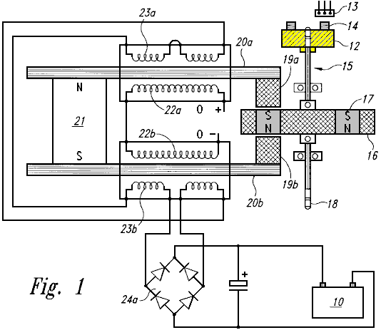
Fig.1a is a side view of a timing wheel and magnetic Hall-effect sensor of the back EMF motor generator.
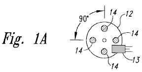
Fig.1b is a side view of the rotor of the back EMF motor generator.
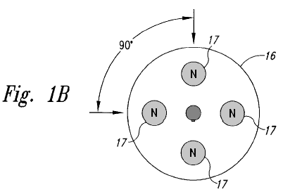
Fig.2 is a schematic drawing incorporating circuitry for the back EMF motor generator.
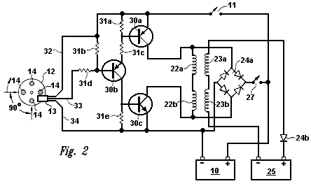
Fig.3 is a box diagram showing the relationships of the back EMF motor generator circuitry.
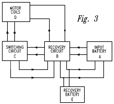
DETAILED
DESCRIPTION OF THE INVENTION
The present invention is a device and method for creating a back EMF permanent electromagnetic motor generator. As described in the Background Information, this new motor generator conforms to all applicable electrodynamic laws of physics and is in harmony with the law of the conservation of energy, the laws of electromagnetism and other related natural laws.
The back EMF permanent electromagnetic motor generator is comprised of a combination of electrical, material and magnetic elements, arranged to capture available electromagnetic energy (back EMF) in a recovery rectifier or single diode from output coils. The capturing of back EMF energy is also known as ‘regauging’. As an arbitrary starting point in describing this invention, an input battery, as a means of energy, sends power through a power on-off switch and then to a timing mechanism, such as a magnetic timing switch (a semiconductor Hall-effect magnetic pickup switch) which is triggered by a magnet on a timing wheel. The timing wheel may contain any number of magnets (i.e. one or more), with the South poles facing outwards and aligned with the Hall-effect pickup switch.
The timing wheel is mounted at the end of a shaft which is located along the centreline of a rotor, which in turn, may contain any number of magnets (i.e. two or more). The rotor magnets are arranged so that they have the same polarity and are equidistant from each other. The shaft has the timing wheel mounted at one end, the rotor, and then some means for performing work, such as a power take off at the opposite end. However, there are other embodiments in which the position of the rotor, timing wheel and power take-off have other configurations. The rotor is mounted on a platform or housing which is fixed in a stationary position within a stator.
The stator is comprised of a permanent magnet connected to a means for conducting electromagnetic energy such as two parallel bars, each bar having a magnetised pole piece at one end. The conduction material of the bar may be ferrous, powdered iron, silicon steel, stainless magnetic steel, laminations of conductive material or any other magnetic conductive material. Each bar has an input coil placed around it. The coil may be constructed from copper, aluminium or any other suitable conductive material. The primary or input coil is connected to the switching circuit. A second coil on top of the input coil becomes a secondary or output coil. The secondary or output coil is connected to the recovery circuit. The rotor is located symmetrically between the pole pieces of the bars of the stator and it contains a series of magnets all having the same polarity, North or South, with each magnet in the rotor being in aligned with the pole piece as the rotor rotates.
When the rotor is energised from the battery of the switching circuit, there is an initial magnetic field that is instantly overcome as the magnetised pole pieces align with the rotor magnets. As the rotor begins to move, increasing electromagnetic energy is produced as a result of flux gaiting from the aligned magnets of the rotor and pole pieces. The coils surrounding the bars "buck" the permanent magnet connecting the bars. This is known as the "buck boosting" principle. When the permanent magnet is bucked by the coils, it reverses the polarity of the pole pieces which are aligned with the rotor magnets causing the rotor to increase its rate of rotation. The energy available from the fields that are collapsing in the primary and secondary coils, (which creates the back EMF within the system), is now in non-equilibrium. Energy can now be put back into the system via the switching circuitry. Available energy captured from the back EMF, may be applied in different directions, including re-energising the input battery, storage in a capacitor, conversion by a recovery rectifier to be stored in the input battery, a capacitor or a secondary or recovery battery. Recovery rectifiers are used to convert this AC to DC. Available energy may be used to energise an electric bulb, fan or any other uses.
The shaft in the centre of the rotor can transfer energy in the form of work through a power take-off. The power take-off may be connected to any number of secondary shafts, wheels, gears and belts to increase or reduce torque.
This is a description of the basic invention, however, there are an innumerable number of combinations and embodiments of stators, rotors, Hall-effect magnetic pickup switches, coils, recovery rectifiers and electronic connecting modes that may be combined on a single shaft or several shafts connected in various combinations and sequences, and of various sizes. There may be any number of stators to one rotor, (however, there can be only one active rotor if there is a single stator). The number of Hall-effect pickup switches may vary, for example, in the case of multiple stators of high resistant coils, the coils may be parallel to form a low resistant coil so that one Hall-effect pickup with one circuit may fire all of the stators at the same time. The number of magnets in both the timing wheel and the rotor may also vary in number as well as the size and strength of the magnets. Any type of magnet may be used. The number of turns on both the input and output coils on each conducting bar may also vary in number and in conductive material.
The motor generator, as shown in Fig.1, a top perspective view of a single stator, single rotor back EMF motor and is comprised of a means of providing energy, such as input battery 10 connected to power switch 11 (shown in Fig.2) and Hall-effect magnetic pickup switch 13. Magnetic pickup 13 interfaces with timing wheel 12 to form a timing switch. Timing wheel 12 contains four magnets 14 with the South pole of each said magnet facing outward towards magnetic pickup 13. Timing wheel 12 is fixed at one end of shaft 15. Located on shaft 15 is rotor 16. Rotor 16 can be of any realistic size, and in this example the rotor contains four rotor magnets 17. The rotor magnets 17 are arranged so all have the same polarity.
Opposite timing wheel 12 on shaft 15 is a means for performing work, such as a power take-off 18. Rotor 16 is mounted in a fixed position with rotor magnets 17 in aligned with the magnetised pole pieces 19a and 19b. Each pole piece 19a and 19b is connected to iron bars 20a and 20b. These Iron bars are connected by a permanent magnet 21. Wire is wrapped around iron bars 20a and 20b to form input coils 22a and 22b. Superimposed upon input coils 22a and 22b are output coils 23a and 23b. These output coils are connected to full wave bridge first recovery rectifier 24a which then connects to battery 10.
Fig.1a is a side view of the back EMF Motor Generator timing wheel 12 with Hall-effect magnetic pickup 13 positioned to be triggered by each of the four magnets 14 in turn as timing wheel 12 rotates. The magnets 14 have their South poles facing outward and they are spaced evenly with a 90 degree angular separation.
Fig.1b is a side view of rotor 16 with four rotor magnets 17 with 90 degree angular separation from each other and having the same polarity.
Fig.2 is a schematic diagram of the motor generator circuitry showing input coil connections from input battery 10 through power switch 11, transistors 30a,b,c resistors 31a-e, through power supply lead 32 (“VCC+”) and to magnetic pickup 13. Magnetic pickup 13 is in aligned with timing wheel magnets 14 located on timing wheel 12. Collector lead 33 and ground lead 34 carry the signals from magnetic pickup 13. When current is reversed, it flows through resistor 31e and transistor 30c to input battery 10. Input coils 22a,b send power to full wave bridge first recovery rectifier 24a which then sends power through switch recovery 27 back into the system, and/or to the input battery 10. Output coils 23a and 23b send power through single diode second recovery rectifier 24b to recovery battery 25.
In this particular embodiment, the value and type number of the components are as follows:
Hall-effect magnetic pickup switch 13 is a No. 3020;
Transistor 30a is a 2N2955;
Transistor 30b is an MPS8599;
Transistor 30c is a 2N3055;
Resistors 31a and 31b are 470 ohms
Resistor 31b is 2.2 K ohms
Resistor 31c is 220 ohms
Resistor 31d is 1 K ohms
Recovery rectifier 24a is a 10 Amp, 400 volts bridge rectifier.
Fig.3 is a box diagram showing the flow of voltage from input battery A, through recovery circuit B, switching circuit C and motor coils D. Motor coils D send available back EMF energy through recovery circuit B, and then on to recovery battery E and input battery A. Available back EMF energy can also flow from switching circuit C to recovery circuit B.
In multiple stator/rotor systems, each individual stator may be energised one at a time or all of the stators may be energised simultaneously. Any number of stators and rotors may be incorporated into the design of such multiple stator/rotor motor generator combinations. However, while there may be several stators per rotor, there can only be one rotor for a single stator. The number of stators and rotors that would comprise a particular motor generator is dependent upon the amount of power required in the form of watts. The desired size and horsepower of the motor determines whether the stators will be in parallel or fired sequentially by the magnetic Hall-effect pickup or pickups. The number of magnets incorporated into a particular rotor is dependent upon the size of the rotor and power required of the motor generator. In a multiple stator/rotor motor generator, the timing wheel may have one or more magnets, but must have one magnet Hall-effect pickup for each stator if the stators are not arranged in parallel. The back EMF energy is made available through the reversing of the polarity of the magnetised pole pieces thus collapsing the field around the coils and reversing the flow of energy to the recovery diodes, which are capturing the back EMF.
Individual motors may be connected in sequence, with each motor having various combinations of stators and rotors, or they may be connected in parallel. Each rotor may have any number of magnets ranging from a minimum of 2 to maximum of 60. The number of stators for an individual motor may range from 1 to 60 with the number of conducting bars ranging from 2 to 120.
What distinguishes this motor generator from all others is the presence of a permanent magnet connecting the two conducting bars which transfer magnetic energy through the pole pieces to the rotor, thereby attracting the rotor between the pole pieces. With the rotor attracted in between the two pole pieces, the coils switch the polarity of the magnetic field of the pole pieces so that the rotor is repelled out. Therefore there is no current and voltage being used to attract the rotor. The only current being used is the repulsion of the rotor between the two conductive bar pole pieces thereby requiring only a small amount of current to repel the rotor. This is known as ‘a regauging system’ and allows the capturing of available back EMF energy.
Finally, although the invention has been described with reference of particular means, materials and embodiments, it is to be understood that the invention is not limited to the particulars disclosed and extends to all equivalents within the scope of the claims.
JOHN BEDINI: BATTERY PULSE
CHARGER
US Patent Application 2003/117111 26th June 2003 Inventor: John C. Bedini
DEVICE AND METHOD FOR PULSE-CHARGING A
AND FOR DRIVING OTHER DEVICES WITH A PULSE
This is a slightly reworded copy of this patent application which shows a method of pulse-charging a battery bank or powering a heater and/or a motor. John Bedini is an intuitive genius with very considerable practical ability, so any information coming from him should be considered most carefully. At the end of this document there is some additional information not found in the patent.
ABSTRACT
This two-phase solid-state battery charger can receive input energy from a variety of sources including AC current, a battery, a DC generator, a DC-to-DC inverter, solar cells or any other compatible source of input energy. Phase 1 is the charging phase and Phase 2 is the discharge phase, where a signal, or current, passes through a dual timing switch which independently controls two channels, thus producing the two phases.
The dual timing switch is controlled by a logic chip, or pulse width modulator. A potential charge is allowed to build up in a capacitor bank. The capacitor bank is then disconnected from the energy input source and then a high voltage pulse is fed into the battery which is there to receive the charge. The momentary disconnection of the capacitor from the input energy source allows a free-floating potential charge in the capacitor. Once the capacitor has completed discharging the potential charge into the battery, the capacitor disconnects from the charging battery and re-connects to the energy source, thus completing the two-phase cycle.
TECHNICAL
FIELD
This invention relates generally to a battery pulse-charger using a solid-state device and method where the current going to the battery is not constant. The signal or current is momentarily switch-interrupted as it flows through either the first channel, (the charging phase), or the second channel, (the discharging phase). This two-phase cycle alternates the signal in the two channels thereby allowing a potential charge in a capacitor to disconnect from its power source an instant before the capacitor discharges its stored potential energy into a battery set up to receive the capacitor's stored energy. The capacitor is then disconnected from the battery and re-connected to the power source upon completion of the discharge phase, thereby completing the charge-discharge cycle. The battery pulse-charger can also drive devices, such as a motor and a heating element, with pulses.
BACKGROUND
AND PRIOR ART
Present day battery chargers use a constant charge current in their operation with no momentary disconnection of the signal or current as it flows either: (1) from a primary energy source to the charger; or (2) from the charger itself into a battery for receiving the charge. Some chargers are regulated to a constant current by any of several methods, while others are constant and are not regulated. There are no battery chargers currently in the art or available wherein there is a momentary signal or current disconnection between the primary energy source and the charger capacitors an instant before the capacitors discharge the stored potential energy into a battery receiving the pulse charge. Nor are there any chargers in the art that disconnect the charger from the battery receiving the charge when the charger capacitors receive energy from the primary source. The momentary current interruption allows the battery a short "rest period" and requires less energy from the primary energy source while putting more energy into the battery receiving the charge while requiring a shorter period of time to do it.
SUMMARY OF
THE INVENTION
One aspect of the invention relates to a solid-state device and method for creating a pulse current to pulse-charge a battery or a bank of batteries in which a new and unique method is used to increase and preserve, for a longer period of time, the energy stored in the battery, as compared to constant-current battery chargers. The device uses a timed pulse to create a DC pulse waveform to be discharged into the battery receiving the charge.
One embodiment of the Invention uses a means for dual switching such as a pulse-width modulator (PWM), for example, a logic chip SG3524N PWM, and a means for optical coupling to a bank of high-energy capacitors to store a timed initial pulse charge. This is the charge phase, or phase 1. The charged capacitor bank then discharges the stored high energy into the battery receiving the charge in timed pulses. Just prior to discharging the stored energy into the battery, the capacitor bank is momentarily disconnected from the power source, thus completing the charge phase, and thereby leaving the capacitor bank as a free-floating potential charge disconnected from the primary energy source to then be discharged into the battery. The transfer of energy from the capacitor bank to the battery completes the discharge phase, or phase 2. The two-phase cycle now repeats itself.
This embodiment of the battery pulse-charger works by transferring energy from a source, such as an AC source, to an unfiltered DC source of high voltage to be stored in a capacitor or a capacitor bank. A switching regulator is set to a timed pulse, for example, a one second pulse that is 180 degrees out of phase for each set of switching functions. The first function is to build the charge in the capacitor bank from the primary energy source; the second function is to disconnect the power source from the capacitor bank; the third function is to discharge the stored high voltage to the battery with a high voltage spike in a timed pulse, for example, a one second pulse; and the fourth function is to re-connect the capacitor bank to the primary energy source.
The device operates through a two-channel on/off switching mechanism or a gauging/re-gauging function wherein the charger is disconnected from its primary energy source an instant before the pulse-charger discharges the high-energy pulse into the battery to be charged. As the primary charging switch closes, the secondary discharging switch opens, and vise-versa in timed pulses to complete the two phase cycle.
The means for
a power supply is varied with several options available as the primary energy
source. For example, primary input
energy may come from an AC source connected into the proper voltage
(transformer); from an AC generator; from a primary input battery; from solar
cells; from a
The Field Effect Transistor (FET) switches can be IRF260 FETs, or any other FET needed to accomplish this function. All the FETs are connected in parallel to achieve the proper current handling capacity for the pulses. Each FET may be connected through a 7-watt, 0.05-ohm resistor with a common bus connection at the source. All the FET gates may be connected through a 240-ohm resistor to a common bus. There may also be a 2 K-ohm resistor wired between the FET gates and the drain bus.
A transistor, for example an MJE15024, can be used as a driver for the gates, driving the bus, and in turn, an optical coupler powers the driver transistor through the first channel. A first charging switch is used to charge the capacitor bank, which acts as a DC potential source to the battery. The capacitor bank is then disconnected from the power rectifier circuit. The pulse battery charger is then transferred to a second field effect switch through the second channel for the discharge phase. The discharge phase is driven by a transistor, and that transistor is driven via an optical coupler. When the second (discharge) switch is turned on, the capacitor bank potential charge is discharged into the battery waiting to receive the charge. The battery receiving the charge is then disconnected from the pulse-charger capacitor bank in order to repeat the cycle. The pulse-charger may have any suitable source of input power including:
(1) solar panels to raise the voltage to the capacitor bank;
(2) a wind generator;
(3) a
(4) an alternator;
(5) an AC motor generator;
(6) a static source such as a high voltage spark; and
(7) other devices which can raise the potential of the capacitor bank.
In another embodiment of the invention, one can use the pulse-charger to drive a device such as a motor or heating element with pulses of energy.
BRIEF DESCRIPTION OF THE DRAWINGS

Fig.1 is a schematic drawing of a solid-state pulse-charger according to an embodiment of the invention.
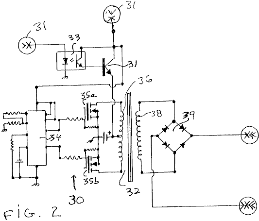
Fig.2 is a schematic drawing of a
conventional
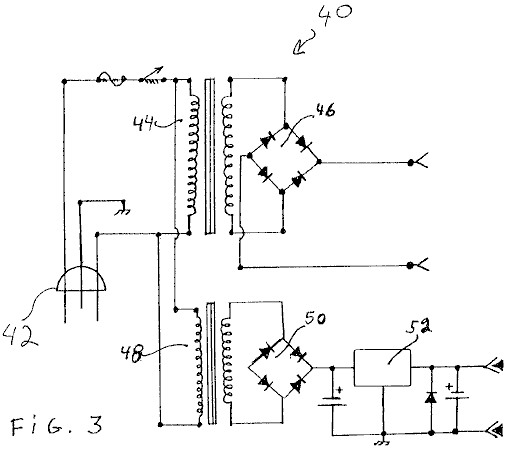
Fig.3 is a schematic drawing of a conventional AC power supply that can be used to provide power to the pulse-charger of Fig.1 according to an embodiment of the invention.
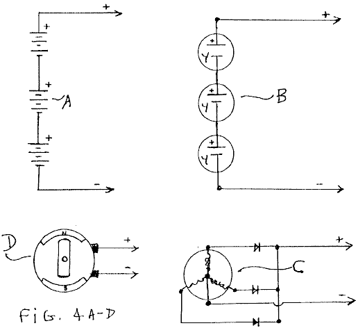
Fig.4A to Fig.4D are schematic drawings of other conventional power supplies that can be used to provide power to the pulse-charger of Fig.1 according to an embodiment of the invention.
Fig.5 is a block diagram of the solid-state pulse-charger of Fig.1 according to an embodiment of the invention.
Fig.6 is a diagram of a DC motor that the pulse-charger of Fig.1 can drive according to an embodiment of the invention.
Fig.7 is a diagram of a heating element that the pulse-charger of Fig.1 can drive according to an embodiment of the invention.
DETAILED
DESCRIPTION OF THE INVENTION
An embodiment of the present invention is a device and method for a solid-state pulse-charger that uses a stored potential charge in a capacitor bank. The solid-state pulse-charger comprises a combination of elements and circuitry to capture and store available energy in a capacitor bank. The stored energy in the capacitors is then pulse-charged into the battery to be charged. In one version of this embodiment, there is a first momentary disconnection between the charger and the battery receiving the charge during the charge phase of the cycle, and a second momentary disconnection between the charger and the input energy source during the discharge phase of the cycle.
As a starting point, and an arbitrary method in describing this device and method, the flow of an electrical signal or current will be tracked from the primary input energy to final storage in the battery receiving the pulse charge.
Fig.1 is a schematic drawing of the solid-state pulse-charger according to an embodiment of the invention. As shown in Fig.1, the primary input energy source to the pulse-charger is a power supply 11, examples of which are shown in Fig.2, Fig.3, and Figs.4A-4D. A 12-volt battery, as a low voltage energy source 12, drives a dual switching means of control such as a logic chip or a pulse-width modulator (PWM) 13.
Alternatively, the voltage from the power supply 11 may be converted to a voltage suitable to power the PWM 13. The PWM 13 may be an SG3524N logic chip, and functions as an oscillator or timer to drive a 2-channel output with "on/off" switches that are connected when on to either a first optical isolator 14, or alternatively, to a second optical isolator 15. The first and second optical isolators 14 and 15 may be H11D3 optical isolators. When the logic chip 13 is connected to a first channel, it is disconnected from a second channel, thus resulting in two phases of signal direction; phase 1, a charge phase, and phase 2, a discharge phase.
When the logic chip 13 is switched to the charge phase, the signal flows to the first optical isolator 14. From the optical isolator 14, the signal continues its flow through a first NPN power transistor 16 that activates an N-channel MOSFET 18a and an N-channel MOSFET 18b. Current flowing through the MOSFETs 18a and 18b builds up a voltage across a capacitor bank 20, thereby completing the charge phase of the switching activity.
The discharge phase begins when the logic chip 13 is switched to the second channel, with current flowing to the second optical isolator 15 and then through a second NPN power transistor 17, which activates an N-channel MOSFET 19a and an N-channel MOSFET 19b. After the logic chip 13 closes the first channel and opens the second channel, the potential charge in the capacitor bank 20 is free floating between the power supply 11, from which the capacitor bank 20 is now disconnected, and then connected to a battery 22 to receive the charge. It is at this point in time that the potential charge in the capacitor bank 20 is discharged through a high-energy pulse into the battery 22 or, a bank (not shown) of batteries. The discharge phase is completed once the battery 22 receives the charge. The logic chip 13 then switches the second channel closed and opens the first channel thus completing the charge-discharge cycle. The cycle is repetitive with the logic chip 13 controlling the signal direction into either channel one to the capacitor bank, or to channel two to the battery 22 from the capacitor bank. The battery 22 is given a momentary rest period without a continuous current during the charge phase.
The component values for the described embodiment are as follows. The resistors 24, 26, . . . 44b have the following respective values: 4.7K, 4.7K, 47K, 330, 330, 2K, 47, 47, 0.05(7W), 0.05(7W), 2K, 47, 47, 0.05(7 W), and 0.05(7W). The potentiometer 46 is 10K, the capacitor 48 is 22 mF, and the total capacitance of the capacitor bank 20 is 0.132F. The voltage of the battery 22 is between 12-24 V, and the voltage of the power supply 11 is 24-50 V such that the supply voltage is approximately 12-15 V higher than the battery voltage.
Other embodiments of the pulse-charger are contemplated. For example, the bipolar transistors 16 and 17 may be replaced with field-effect transistors, and the transistors 18a, 18b, 19a, and 19b may be replaced with bipolar or insulated-gate bipolar (IGBT) transistors. Furthermore, one can change the component values to change the cycle time, the peak pulse voltage, the amount of charge that the capacitor bank 20 delivers to the battery 22, etc. In addition, the pulse-charger can have one or more than two transistors 18a and 18b, and one or more than two transistors 19a and 19b.
Still referring to Fig.1, the operation of the above-discussed embodiment of the pulse-charger is discussed. To begin the first phase of the cycle during which the capacitor bank 20 is charged, the logic circuit 13 deactivates the isolator 15 and activates the isolator 14. Typically, the circuit 13 is configured to deactivate the isolator 15 before or at the same time that it activates the isolator 14, although the circuit 13 may be configured to deactivate the isolator 15 after it activates the isolator 14.
Next, the activated isolator 14 generates a base current that activates the transistor 16, which in turn generates a current that activates the transistors 18a and 18b. The activated transistors 18a and 18b charge the capacitors in the bank 20 to a charge voltage equal or approximately equal to the voltage of the power supply 11 less the lowest threshold voltage of the transistors 18a and 18b. To begin the second phase of the cycle during which the capacitor bank 20 pulse charges the battery 22, the logic circuit 13 deactivates the isolator 14 and activates the isolator 15. Typically, the circuit 13 is configured to deactivate the isolator 14 before or at the same time that it activates the isolator 15, although the circuit 13 may be configured to deactivate the isolator 14 after it activates the isolator 15.
Next, the activated isolator 15 generates a base current that activates the transistor 17, which in turn generates a current that activates the transistors 19a and 19b. The activated transistors 19a and 19b discharge the capacitors in the bank 20 into the battery 22 until the voltage across the bank 20 is or is approximately equal to the voltage across the battery 22 plus the lowest threshold voltage of the transistors 19a and 19b. Alternatively, the circuit 13 can deactivate the isolator 15 at a time before the bank 20 reaches this level of discharge. Because the resistances of the transistors 19a and 19b, the resistors 44a and 44b, and the battery 22 are relatively low, the capacitors in the bank 20 discharge rather rapidly, thus delivering a pulse of current to charge the battery 22. For example, where the pulse-charger includes components having the values listed above, the bank 20 delivers a pulse of current having a duration of about 100 ms and a peak of about 250 A.
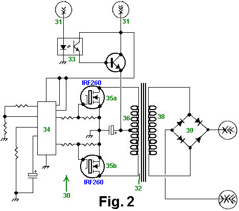
Fig.2 is a schematic drawing of a
conventional
Fig.3 is a schematic drawing of an AC power supply 40 that can be used as both the power supply 11 and the power supply 12 of Fig.1 according to an embodiment of the invention. The power input 42 to the supply 40 is 120V AC. A first transformer 44 and full-wave rectifier 46 compose the supply 11, and a second transformer 48, full-wave rectifier 50, and voltage regulator 52 compose the supply 12.
Fig.4A to Fig.4D are schematic drawings of various conventional primary energy input sources which can be used as the supply 11 and/or the supply 12 of Fig.1 according to an embodiment of the invention. Fig.4A is a schematic drawing of serially coupled batteries. Fig.4B is a schematic drawing of serially-coupled solar cells. Fig.4C is a schematic drawing of an AC generator, and Fig.4D is a schematic drawing of a DC generator.
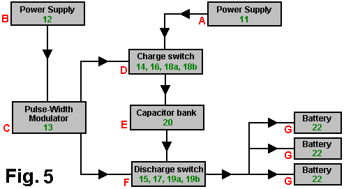
Fig.5 is a block diagram of the solid-state pulse-charger of Fig.1 according to an embodiment of the invention. Block A is the power supply 11, which can be any suitable power supply such as those shown in Fig.2, Fig.3, Figs.4A-4D. Block B is the power supply 12, which can be any suitable power supply such as a 12V DC supply or the supply shown in Fig.3. Block C is the PWM 13 and its peripheral components. Block D is the charge switch that includes the first optical isolator chip 14, the first NPN power transistor 16, the first set of two N-channel MOSFETs 18a and 18b, and their peripheral resistors. Block E is the capacitor bank 20. Block F is the discharge switch that includes the second optical isolator chip 15, the second NPN power transistor 17, the second set of two N-channel MOSFETs 19a and 19b, and their peripheral resistors. Block G is the battery or battery bank 22 which is being pulse-charged.
A unique feature that distinguishes one embodiment of the pulse-charger described above, from conventional chargers is the method charging the battery with pulses of current instead of with a continuous current. Consequently, the battery is given a reset period between pulses.
Fig.6 is a diagram of a DC motor 60 that the pulse-charger of Fig.1 can drive according to an embodiment of the invention. Specifically, one can connect the motor 60 in place of the battery 22 (Fig.1) such that the pulse-charger drives the motor with pulses of current. Although one need not modify the pulse-charger to drive the motor 60, one can modify it to make it more efficient for driving the motor. For example, one can modify the values of the resistors peripheral to the PWM 13 (Fig.1) to vary the width and peak of the drive pulses from the capacitor bank 20 (Fig.1).
Fig.7 is a diagram of a heating element 70, such as a dryer or water-heating element, that the pulse-charger of Fig.1 can drive according to an embodiment of the invention. Specifically, one can connect the heating element 70 in place of the battery 22 (Fig.1) such that the pulse-charger drives the element with pulses of current. Although one need not modify the pulse-charger to drive the element 70, one can modify it to make it more efficient for driving the element. For example, one can modify the values of the resistors peripheral to the PWM 13 (Fig.1) to vary the width and peak of the drive pulses from the capacitor bank 20 (Fig.1).
In the embodiments discussed above, specific electronic elements and components are used. However, it is known that a variety of available transistors, resistors, capacitors, transformers, timing components, optical isolators, pulse width modulators, MOSFETs, and other electronic components may be used in a variety of combinations to achieve an equivalent result. Finally, although the invention has been described with reference of particular means, materials and embodiments, it is to be understood that the invention is not limited to the particulars disclosed and extends to all equivalents within the scope of the claims.
Notes:
The following information is NOT part of John’s patent. It is information intended to be helpful, but as it is not coming from John it must be considered to be opinion and not fact. In the above diagrams, the SG3524N integrated circuit is likely to be unfamiliar to many readers, and an examination of the specification sheet does not make it obvious which pin connections are used in John’s circuit. The following pin connections are believed to be correct, but cannot be guaranteed.
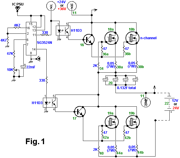
In addition to these SG3524N pin connections, it is suggested that pins 1, 4 and 5 be connected to ground instead of just pin 8, and that a 100nF capacitor be connected from pin 9 to ground. Pins 3 and 10 are left unconnected. The pinouts for the chip are:
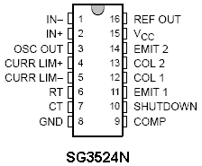
HERMANN PLAUSON
US Patent 1,540,998
9th June 1925
Inventor: Hermann Plauson
CONVERSION OF ATMOSPHERIC ELECTRIC ENERGY
Please note
that this is a re-worded excerpt from this patent. It describes in considerable detail, different
methods for abstracting useable electrical power from passive aerial
systems. He describes a system with 100
kilowatt output as a “small” system.
Be it known
that I, Hermann Plauson, Estonian subject, residing in
According to this invention, charges of atmospheric electricity are not directly converted into mechanical energy, and this forms the main difference from previous inventions, but the static electricity which runs to earth through aerial conductors in the form of direct current of very high voltage and low current strength is converted into electro-dynamic energy in the form of high frequency vibrations. Many advantages are thereby obtained and all disadvantages avoided.
The very high voltage of static electricity of a low current strength can be converted by this invention to voltages more suitable for technical purposes and of greater current strength. By the use of closed oscillatory circuits it is possible to obtain electromagnetic waves of various amplitudes and thereby to increase the degree of resonance of such current. Such resonance allows various values of inductance to be chosen which, by tuning the resonance between a motor and the transformer circuit, allows the control of machines driven by this system. Further, such currents have the property of being directly available for various uses, other than driving motors, including lighting, heating and use in electro-chemistry.
Further, with such currents, a series of apparatus may be fed without a direct current supply through conductors and the electro-magnetic high frequency currents may be converted by means of special motors, adapted for electro-magnetic oscillations, into alternating current of low frequency or even into high voltage direct current.
DESCRIPTION OF THE DRAWINGS

Fig.1 is an explanatory figure
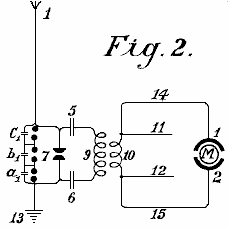
Fig.2 is a diagrammatic view of the most simple form.
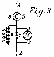
Fig.3 shows a method of converting atmospheric electrical energy into a form suitable for use with motors.
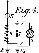
Fig.4 is a diagram showing the protective circuitry.

Fig.5 is a diagram of an arrangement for providing control
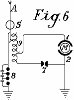
Fig.6 is an arrangement including a method of control
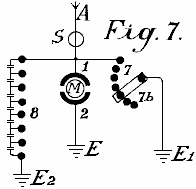
Fig.7 shows how the spark gap can be adjusted
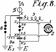
Fig.8 shows a unipolar connection for the motor
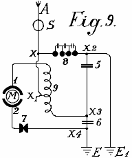
Fig.9 shows a weak coupled system suitable for use with small power motors
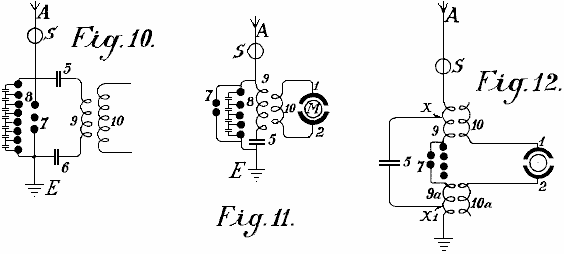
Fig.10, Fig.11 and Fig.12 show modified arrangements
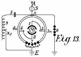
Fig.13 shows a form of inductive coupling for the motor circuit
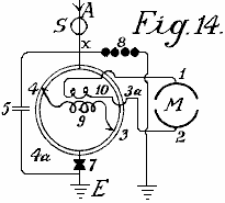
Fig.14 is a modified form of Fig.13 with inductive coupling.
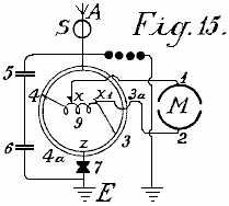
Fig.15 is an arrangement with non-inductive motor
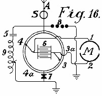
Fig.16 is an arrangement with coupling by capacitor.
Fig.17, Fig.18 and Fig.19 are diagrams showing further modifications
Fig.20 shows a simple form in which the aerial network is combined with special collectors
Fig.21 shows diagramatically, an arrangement suitable for collecting large quantities of energy.
Fig.22 is a modified arrangement having two rings of collectors
Fig.23 shows the connections for three rings of collectors
Fig.24 shows a collecting balloon and diagram of its battery of capacitors
Fig.25 and Fig.26 show modified collector balloon arrangements.
Fig.27 shows a second method of connecting conductors for the balloon aerials.
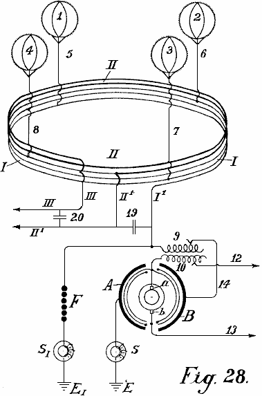
Fig.28 shows an auto-transformer method of connection.
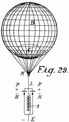
Fig.29 shows the simplest form of construction with incandescent cathode.
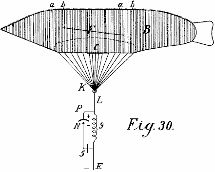
Fig.30 shows a form with a cigar-shaped balloon.
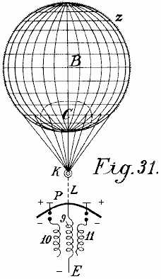
Fig.31 is a modified arrangement.
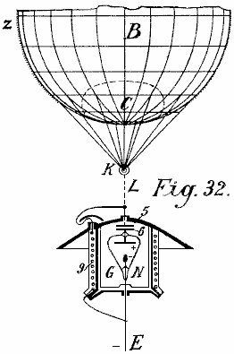
Fig.32 shows a form with cathode and electrode enclosed in a vacuum chamber.
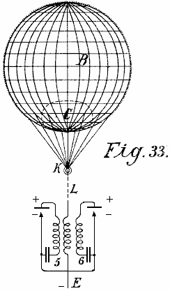
Fig.33 is a modified form of Fig.32
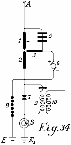
Fig.34 shows an arc light collector.
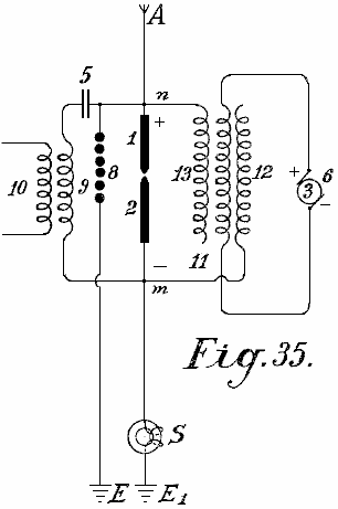
Fig.35 shows such an arrangement for alternating current
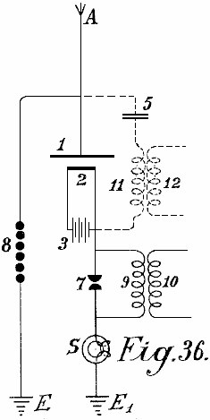
Fig.36 shows an incandescent collector with Nernst lamp
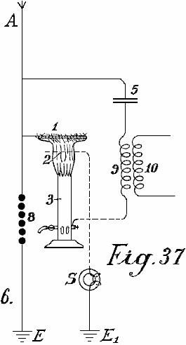
Fig.37 shows a form with a gas flame.
____________________________________________________________________________________________
Fig.1 illustrates a simple diagram for converting static electricity into dynamic energy of a high number of oscillations. For the sake of clarity, a Wimshurst machine is assumed to be employed and not an aerial antenna. Items 13 and 14 are combs for collecting the static electricity of the influence machine. Items 7 and 8 are spark-discharging electrodes. Items 5 and 6 are capacitors, 9 is the primary winding of an inductive coil, 10 is the secondary winding whose ends are 11 and 12. When the disc of the static influence machine is rotated by mechanical means, the combs collect the electric charges, one being positive and one negative and these charge the capacitors 5 and 6 until such a high voltage is developed across the spark gap 7-- 8 that the spark gap is jumped. As the spark gap forms a closed circuit with capacitors 5 and 6, and inductive resistance 9, as is well known, waves of high frequency electromagnetic oscillations will pass in this circuit.
The high frequency of the oscillations produced in the primary circuit induces waves of the same frequency in the secondary circuit. Thus, in the primary circuit, electromagnetic oscillations are formed by the spark and these oscillations are maintained by fresh charges of static electricity.
By suitably selecting the ratio between the number of turns in the primary and secondary windings, with regard to a correct application of the coefficients of resonance (capacitance, inductance and resistance) the high voltage of the primary circuit may be suitably converted into a low voltage high current output.
When the oscillatory discharges in the primary circuit become weaker or cease entirely, the capacitors are charged again by the static electricity until the accumulated charge again breaks down across the spark gap. All this is repeated as long as electricity is produced by the static machine through the application of mechanical energy to it.
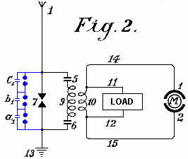
An elementary form of the invention is shown in Fig.2 in which two spark gaps in parallel are used, one of which may be termed the working gap 7 while the second serves as a safety device for excess voltage and consists of a larger number of spark gaps than the working section, the gaps being arranged in series and which are bridged by very small capacitors a1, b1, c1, which allow uniform sparking in the safety section.
1 is the aerial antenna for collecting charges of atmospheric electricity, 13 is the earth connection of the second part of the spark gap, 5 and 6 are capacitors and 9 is the primary coil winding. When the positive atmospheric electricity seeks to combine with the negative earth charge via aerial 1, this is prevented by the air gap between the spark gaps. The resistance of spark gap 7 is lower than that of the safety spark gap set of three spark gaps connected in series a which consequently has three times greater air resistance.
Therefore, so long as the resistance of spark gap 7 is not overloaded, discharges take place only through it. However, if the voltage is increased by any influence to such a level that it might be dangerous for charging the capacitors 5 and 6, or for the coil insulation of windings 9 and 10, the safety spark gap set will, if correctly set, discharge the voltage directly to earth without endangering the machine. Without this second spark gap arrangement, it is impossible to collect and render available large quantities of electrical energy.
The action of this closed oscillation circuit consisting of spark gap 7, two capacitors 5 and 6, primary coil 9 and secondary coil 10, is exactly the same as that of Fig.1 which uses a Wimshurst machine, the only difference being the provision of the safety spark gap. The high frequency electromagnetic alternating current can be tapped off through the conductors 11 and 12 for lighting and heating purposes. Special motors adapted for working with static electricity or high frequency oscillations may be connected at 14 and 15.
In addition to the use of spark gaps in parallel, a second measure of security is also necessary for taking the current from this circuit. This is the introduction of protective electromagnets or choking coils in the aerial circuit as shown by S in Fig.3. A single electromagnet having a core of the thinnest possible separate laminations is connected with the aerial. In the case of high voltages in the aerial network or at places where there are frequent thunderstorms, several such magnets may be connected in series.
In the case of large units, several such magnets can be employed in parallel or in series parallel. The windings of these electromagnets may be simply connected in series with the aerials. In this case, the winding preferably consists of several thin parallel wires, which together, make up the necessary cross-sectional area of wire. The winding may be made of primary and secondary windings in the form of a transformer. The primary winding will then be connected in series with the aerial network, and the secondary winding more or less short-circuited through a regulating resistor or an induction coil. In the latter case it is possible to regulate, to a certain extent, the effect of the choking coils. In the following circuit and constructional diagrams , the aerial electromagnet choke coil is indicated by a simple ring S.
Fig.3 shows the most simple way of converting atmospheric electricity into electromagnetic wave energy by the use of special motors adapted for high oscillatory currents or static charges of electrical energy. Recent improvements in motors for working with static energy and motors working by resonance, that is to say, having groups of tuned electromagnetic co-operating circuits render this possible but such do not form part of the present invention.
A motor adapted to operate with static charges, will for the sake of simplicity, be shown in the diagrams as two semi-circles 1 and 2 and the rotor of the motor by a ring M (Fig.3). A is a vertical aerial or aerial network. S is the safety choke or electromagnet with coil O as may be seen is connected with the aerial A. Adjacent to the electromagnet S, the aerial conductor is divided into three circuits, circuit 8 containing the safety spark gap, circuit 7 containing the working spark gap, and then a circuit containing the stator terminal 1, the rotor and stator terminal 2 at which a connection is made to the earth wire. The two spark gaps are also connected metallically with the earth wire. The method of working in these diagrams is as follows:
The positive atmospheric electric charge collected tends to combine with the negative electricity (or earth electricity) connected via the earth wire. It travels along the aerial A through the electromagnet S without being checked as it flows in the same direction as the direct current. Further, its progress is arrested by two spark gaps placed in the way and the stator capacitors. These capacitors charge until their voltage exceeds that needed to jump the spark gap 7 when a spark occurs and an oscillatory charge is obtained via the closed oscillation circuit containing motor M. The motor here forms the capacity and the necessary inductance and resistance, which as is well known, are necessary for converting static electricity into electromagnetic wave energy.
The discharges are converted into mechanical energy in special motors and cannot reach the aerial network because of the electromagnet or choke. If, however, when a spark occurs at spark gap 7, a greater quantity of atmospheric electricity tends to flow to earth, then a counter voltage is induced in the electromagnet, which is greater the more rapidly and strongly the flow of current direct to earth is. This opposing voltage causes the circuit to exhibit a sufficiently high resistance to prevent a short circuit between the atmospheric electricity and the earth.
The circuit containing spark gap 8, having a different wave length which is not in resonance with the natural frequency of the motor, does not endanger the motor and serves as security against excess voltage, which, as practical experiments have shown, may still arise in certain cases.
In Fig.4, spark gap 7 is shunted across capacitors 5 and 6 from the motor M. This arrangement provides improved over-voltage protection for the motor and it gives a uniform excitation through the spark gap 7.
Fig.5 shows an arrangement for producing large currents which can be used direct without motors, to provide heating and lighting. The main difference here is that the spark gap consists of a star-shaped disc 7 which can rotate on its own axis and is rotated by a motor opposite similarly fitted electrodes 7a. When separate points of starts face one another, discharges take place, thus forming an oscillation circuit with capacitors 5 and 6 and inductor 9. It is evident that a motor may also be connected directly to the ends of inductor 9.
Fig.6 shows how the oscillation circuit may have a motor connected via a variable inductor which opposes any excess voltages which might be applied to the motor. By cutting the separate coils 9 (coupled inductively to the aerial) in or out, the inductive action on the motor may be more or less increased, or variable aerial action may be exerted on the oscillation circuit.
In Fig.7 the oscillation circuit is closed through the earth (E and E1). The spark gap 7 may be increased or reduced by means of a contact arm 7b.
Fig.8 shows a unipolar connection of the motor with the aerial network. Here, two oscillation circuits are closed through the same motor. The first oscillation circuit passes from aerial A through electromagnet S, point x, inductance 9a to the earth capacitor 6, across spark gap 7 to the aerial capacitor 5 and back to point x. The second oscillation circuit starts from the aerial 5 at the point x1 through inductor 9 to the earth capacitor 6 at the point x3, through capacitor 6, across spark gap 7 back to point x1. The motor itself, is inserted between the two points of spark gap 7. This arrangement produces slightly dampened oscillation wave currents.
Fig.9 shows a loosely coupled system intended for small motors for measuring purposes. A is the serial, S is the electromagnet or aerial inductor, 9 the inductor, 7 the spark gap, 5 and 6 capacitors, E the earth, M the motor, and 1 and 2 the stator connections of the motor which is directly connected to the oscillator circuit.
Fig.10 shows a motor circuit with purely inductive coupling. The motor is connected with the secondary wire 10 as may be seen in Fig.11 in a somewhat modified circuit. The same applies to the circuit of Fig.12.
The circuit diagrams shown so far, allow motors of small to medium strength to be operated. For large aggregates, however, they are too inconvenient as the construction of two or more oscillation circuits for large amounts of energy is difficult; the governing is still more difficult and the danger in switching on or off is greater.
A means for overcoming such difficulties is shown in Fig.13. The oscillation circuit shown here, runs from point x over capacitor 5, variable inductor 9, spark gap 7 and the two segments 3a and 3b forming arms of a Wheatstone bridge, back to x. If the motor is connected by brushes 3 and 4 transversely to the two arms of the bridge as shown in the drawing, electromagnetic oscillations of equal sign are induced in the stator surfaces 1 and 2 and the motor does not revolve. If however, the brushes 3 and 4 are moved in common with the conducting wires 1 and 2 which connect the brushes with the stator poles, a certain alteration or displacement of the polarity is obtained and the motor commences to revolve.
The maximum action will result if one brush 3 comes on the central sparking contact 7 and the other brush 4 on the part x. In practice however, they are usually brought on to the central contact 7 but only held in the path of the bridge segments 4a and 3a in order to avoid connecting the spark gaps with the motor oscillation circuit.
As this prevents the whole of the oscillation energy acting on the motor, it is better to adopt the modification shown in Fig.14. The only difference here is that the motor is not wired directly to the segments of the commutator, but instead it is wired to secondary coil 10 which receives induced current from primary coil 9. This arrangement provides a good transforming action, a loose coupling and an oscillation circuit without a spark gap.
In Fig.15, the motor is wired directly to the primary coil at x and x1 after the principle of the auto-transformer. In Fig.16, instead of an inductor, capacitor 6 replaces the inductance and is inserted between the segments 3a and 4a. This has the advantage that the segments 3a and 4a need not be made of solid metal, but may consist of spiral coils which allow a more exact regulation, and high inductance motors may be used.
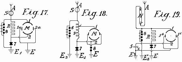
The circuits shown in Fig.17, Fig.18 and Fig.19 may be used with resonance and particularly with induction capacitor motors; between the large stator induction capacitor surfaces, small reversing pole capacitors are connected which are lead together to earth. Such reversing poles have the advantage that, with large quantities of electrical energy, the spark formation between the separate oscillation circuits ceases.
Fig.19 shows another method which prevents high frequency electromagnetic oscillations formed in the oscillation circuit, feeding back to the aerial. It is based on the well known principle that a mercury lamp, one electrode of which is formed of mercury, the other of solid metal such as steel, allows an electric charge to pass in only one direction: from the mercury to the steel and not vice versa. The mercury electrode of the vacuum tube N is therefore connected with the aerial conductor and the steel electrode with the oscillation circuit. Charges can then only pass from the aerial through the vacuum tube to the oscillation circuit and no flow occurs in the opposite direction. In practice, these vacuum tubes must be connected behind an electromagnet as the latter alone provides no protection against the danger of lightning.
As regards the use of spark gaps, all arrangements as used for wireless telegraphy may be used. Of course, the spark gaps in large machines must have a sufficiently large surface. In very large stations they are cooled in liquid carbonic acid or better still, in liquid nitrogen or hydrogen; in most cases the cooling may also take place by means of liquefied low homologues of the metal series or by means of hydrocarbons, the freezing point of which lies between -90oC and -400C. The spark gap casing must also be insulated and be of sufficient strength to be able to resist any pressure which may arise. Any undesirable excess super-pressure which may be formed must be let off automatically. I have employed with very good results, mercury electrodes which were frozen in liquid carbonic acid, the cooling being maintained during the operation from the outside, through the walls.
Fig.20 shows one of the most simple forms of construction of an aerial network in combination with collectors, transformers and the like. E is the earth wire, 8 the safety spark gap, 7 the working spark gap, 1 and 2 the stator surfaces of the motor, 5 a capacitor battery, S the protective magnet which is connected with the coil in the aerial conductor, A1 to A10 aerial antennae with collecting balloons, N horizontal collecting or connecting wires, from which, a number of connections run to the centre.
The actual collectors consist of metal sheaths, preferably made of an aluminium magnesium alloy, and are filled with hydrogen or helium, and are attached to copper-plated steel wires. The size of the balloon is selected so that the actual weight of the balloon and its conducting wire is supported by it. Aluminium spikes, made and gilded as described below, are arranged on top of the balloons in order to produce a conductor action. Small quantities of radium preparations, more particularly, polonium-ionium or mesothorium preparations, considerably increase the ionisation, and the performance of these collectors.
In addition to metal balloons, fabric balloons which are sprayed with a metallic coating according to Schoop’s metal-spraying process may also be used. A metallic surface may also be produced by lacquering with metallic bronzes, preferably according to Schoop’s spraying process, or lacquering with metallic bronze powders in two electrical series of widely different metals, because this produces a considerably increased collecting effect.
Instead of the ordinary round balloons, elongated cigar-shaped ones may be employed. In order also to utilise the frictional energy of the wind, patches or strips of non-conducting substances which produce electricity by friction, may be attached to the metallised balloon surfaces. The wind will impart a portion of its energy in the form of frictional electricity, to the balloon casing, thus substantially increasing the collection effect.
In practice however, very high towers of up to 300 metres may be employed as antennae. In these towers, copper tubes rise freely further above the top of the tower. A gas lamp secured against the wind is then lit at the point of the copper tube and a netting is secured to the copper tube over the flame of this lamp to form a collector. The gas is conveyed through the interior of the tube, up to the summit. The copper tube must be absolutely protected from moisture at the place where it enters the tower, and rain must be prevented from running down the walls of the tower, which might lead to a bad catastrophe. This is done by bell-shaped enlargements which expand downwards, being arranged in the tower in the form of high voltage insulators of Siamese pagodas.
Special attention must be devoted to the foundations of such towers. They must be well insulated from the ground, which may be achieved by first embedding a layer of concrete in a box form to a sufficient depth in the ground, and inserting in this, an asphalt lining and then glass bricks cast about 1 or 2 metres in thickness. Over this in turn, there is a ferro-concrete layer in which alone the metal foot of the tube is secured. This concrete block must be at least 2 metres from the ground and at the sides, be fully protected from moisture by a wooden covering. In the lower part of the tower, a wood or glass housing should be constructed to protect the capacitors and/or motors. In order to ensure that the ground lead connects to the water-table, a well insulated pit lined with vitreous bricks must be provided. Several such towers are erected at equal distances apart and connected with a horizontal conductor. The horizontal connecting wires may either run directly from tower to tower or be carried on bell-shaped insulators similar to those in use for high voltage electricity transmission lines. The width of the aerial tower network may be of any suitable size and the connection of the motors can take place at any convenient location.
In order to collect large quantities of electricity with few aerials, it is as well to provide the aerial conductor with sets of capacitors as shown in the two methods of construction illustrated in Fig.21 and Fig.22. In Fig.21 the set of capacitors 5 is connected between the aerials Z via lead A and an annular conductor from which horizontal run to the connecting points C to which the earth wire is connected. Fig.22 shows a similar arrangement.
Should two such series of antenna rings be shown by a voltmeter to have a large voltage difference (for example, one in the mountains and one on the plain) or even of a different polarity, these differences may be compensated for by connecting sufficiently large capacitor sets (5, 5a, 5b) by means of Maji star conductors D and D1. Fig.23, shows a connection of three such rings of collectors are positioned in a triangle with a central set of capacitors.
The capacitor sets of such large installations must be embedded in liquefied gasses or in liquids freezing at very low temperatures. In such cases, a portion of the atmospheric energy must be employed for liquefying these gasses. It is also preferable to employ pressure. By this means, the capacitor surfaces may be reduced in area and still allow the storage of large quantities of energy to be stored, secure against breakdown. For the smaller installations, the immersing of the capacitors in well insulated oil or the like, is sufficient. Solid substances, on the other hand, cannot be employed as insulators.
The arrangement in the diagrams shown earlier has always shown both poles of the capacitors connected to the aerial conductors. An improved method of connection has been found to be very advantageous. In this method, only one pole of each capacitor is connected to the collecting network. Such a method of connection is very important, as by means of it, a constant current and an increase in the normal working voltage is obtained. If, for example, a collecting balloon aerial which is allowed to rise to a height of 300 metres, shows 40,000 volts above earth voltage, in practice it has been found that the working voltage (with a withdrawal of the power as described earlier by means of oscillating spark gaps and the like) is only about 400 volts. If however, the capacity of the capacitor surfaces be increased, which capacity in the above mentioned case was equal to that of the collecting surface of the balloon aerials, to double the amount, by connecting the capacitors with only one pole, the voltage rises under an equal withdrawal of current up to and beyond 500 volts. This can only be ascribed to the favourable action of the connecting method.
In addition to this substantial improvement it has also been found preferable to insert double inductances with electromagnets and to place the capacitors preferably between two such electromagnets. It has also been found that the useful action of such capacitors can be further increased if an induction coil is connected as an inductive resistance to the unconnected pole of the capacitor, or still better if the capacitor itself be made as an induction capacitor. Such a capacitor may be compared to a spring, which when compressed, carries in itself accumulated force, which it gives off again when released. In charging, a charge with reversed sign is formed at the other free capacitor pole, and if a short circuit occurs through the spark gap, the accumulated energy is again given back since now new quantities of energy are induced at the capacitor pole connected to the conductor network, which in fact, charges with opposite sign to that at the free capacitor pole. The new induced charges have of course, the same sign as the collector network. The whole voltage energy in the aerial is thereby increased. In the same time interval, larger quantities of energy are accumulated than is the case without such capacitor sets being inserted.
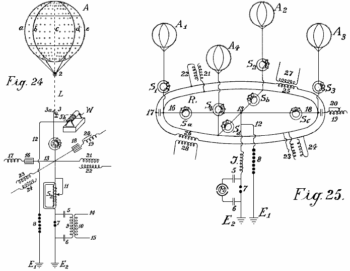
In Fig.24 and Fig.25, two different connection diagrams are illustrated in more detail. Fig.24 shows a collecting balloon along with its earth connections. Fig.25 shows four collecting balloons and the parallel connection of their capacitor sets.
A is the collecting balloon made of an aluminium magnesium alloy (electron metal magnalium) of a specific gravity of 1.8 and a plate thickness of 0.1 mm to 0.2 mm. Inside, there are eight strong vertical ribs of T-shaped section of about 10 mm to 20 mm in height and about 3 mm in thickness, with the projecting part directed inwards (indicated by a, b, c, d and so forth). They are riveted together to form a firm skeleton and are stiffened in a horizontal direction by two cross ribs. The ribs are further connected to one another internally and transversely by means of thin steel wires, whereby the balloon obtains great strength and elasticity. Rolled plates of 0.1 mm to 0.2 mm in thickness made of magnalium alloy are then either soldered or riveted on to this skeleton so that a fully metallic casing with a smooth external surface is created. Well silvered or coppered aluminium plated steel wires run from each rib to the fastening ring 2. Further, the coppered steel hawser L, preferably twisted out of separate thin wires (shown as dotted lines in Fig.24) and which must be long enough to allow the balloon to rise to the desired height, leads to a metal roller or pulley 3 and on to a winch W, which must be well insulated from the earth. By means of this winch, the balloon which is filled with hydrogen or helium, can be allowed to rise to a suitable height of 300 to 5,000 metres, and brought to the ground for recharging or repairs.
The actual current is taken directly through a friction contact from the metal roller 3 or from the wire or even from the winch, or simultaneously from all three by means of brushes (3, 3a and 3b). Beyond the brushes, the conductor is divided, the paths being:- firstly, over 12 to the safety spark gap 8, on to the earth conductor E1, and secondly over electromagnet S1, point 13, to a second loose electromagnet having an adjustable coil S2, then to the spark gap 7 and to the second earth conductor E2. The actual working circuit is formed through the spark gap 7, capacitors 5 and 6, and through the primary coil 9; here the static electricity formed by oscillatory discharges is accumulated and converted into high frequency electromagnetic oscillations. Between the electromagnets S1 and S2 at the crossing point 13, four capacitor sets are introduced which are only indicated diagramatically in the drawings by a single capacitor. Two of these sets of capacitors (16 and 18) are made as plate capacitors and prolonged by regulating induction coils or spirals 17 and 19 while the two others (21 and 23) are induction capacitors. As may be seen from the drawings, each of the four capacitor sets, 16, 18, 21 and 23 is connected by only one pole to either the aerial or to the collector conductor. The second poles 17, 19, 22 and 24 are open. In the case of plate capacitors having no inductive resistance, an induction coil is inserted. The object of such a spiral or coil is the displacement of phase of the induction current by 1/4 periods, whilst the charging current of the capacitor poles which lie free in the air, works back to the collector aerial. The consequence of this is that in discharges in the collector aerial, the back-inductive action of the free poles allows a higher voltage to be maintained in the aerial collecting conductor than would otherwise be the case. It has also been found that such a back action has an extremely favourable effect on the wear of the contacts. Of course, the inductive effect may be regulated at will within the limits of the size of the induction coil, the length of the coil in action being adjustable by means of wire connection without induction (see Fig.24 No. 20).
S1 and S2 may also be provided with such regulating devices, in the case of S2 illustrated by 11. If excess voltage be formed, it is conducted to earth through wire 12 and spark gap 8, or through any other suitable apparatus, since this voltage would be dangerous for the other components. The action of these capacitor sets has already been described.
The small circles on the collector balloon indicate places where small patches of extremely thin layers (0.01 to 0.05 mm thick) of zinc amalgam, gold amalgam or other photoelectric acting metals, are applied to the balloon casing of light metal. Such metallic patches may also be applied to the entire balloon as well as in greater thickness to the conducting network. The capacity of the collector is thereby considerably strengthened at the surface. The greatest possible effect in collecting may be obtained by polonium amalgams and the like. On the surface of the collector balloon, metal points or spikes are also fixed along the ribs. These spikes enhance the charge collection operation. Since it is well known that the sharper the spikes, the less the resistance of the spikes, it is therefore extremely important to use spikes which are as sharp as possible. Experiments have shown that the formation of the body of the spike or point also play a large part, for example, spikes made of bars or rollers with smooth surfaces, have point resistance many times greater than those with rough surfaces. Various kinds of spike bodies have been experimented with for the collector balloons and the best results were given with spikes which were made in the following way: Fine points made of steel, copper, nickel or copper and nickel alloys, were fastened together in bundles and then placed as anode with the points placed in a suitable electrolyte (preferably in hydrochloric acid or muriate of iron solutions) and so treated with weak current driven by 2 to 3 volts. After 2 to 3 hours, according to the thickness of the spikes, the points become extremely sharp and the bodies of the spikes have a rough surface. The bundle can then be removed and the acid washed off with water. The spikes are then placed as cathode in a bath containing a solution of gold, platinum, iridium, palladium or wolfram salts or their compounds, and coated at the cathode galvanically with a thin layer of precious metal, which mush however be sufficiently firm to protect them from atmospheric oxidation.
Such spikes act at a 20 fold lower voltage almost as well as the best and finest points made by mechanical means. Still better results are obtained if polonium or radium salts are added to the galvanic bath when forming the protective layer or coating. Such pins have low resistance at their points and have excellent collector action even at one volt or lower.
In Fig.24, the three unconnected poles are not connected with one another in parallel. That is quite possible in practice without altering the principle of the free pole. It is also preferable to interconnect a series of collecting aerials in parallel to a common collector network. Fig.25 shows such an arrangement. A1, A2, A3, A4 are four metal collector balloons with gold or platinum coated spikes which are electrolytically mad in the presence of polonium emanations or radium salts, the spikes being connected over four electromagnets S1, S2, S3, S4, through an annular conductor R. From this annular conductor, four wires run over four further electromagnets Sa, Sb, Sc, Sd, to the connecting point 13. There, the conductor is divided, one branch passing over 12 and the safety spark gap 7 to the earth at E1, the other over inductive resistance J and working spark gap 7 to the earth at E2. The working circuit, consisting of the capacitors 5 and 6 and a resonance motor or a capacitor motor M, such as already described, is connected in proximity around the sparking gap section 7. Of course, instead of connecting the capacitor motor directly, the primary circuit for high frequency oscillatory current may also be inserted.
The capacitor sets are connected by one pole to the annular conductor R and can be either inductionless (16 and 18) or made as induction capacitors as shown by 21 and 23. The free poles of the inductionless capacitors are indicated by 17 and 19, and those of the induction capacitors by 22 and 24. As may be seen from the drawings, all of these poles 17, 22, 19 and 24 may be interconnected in parallel through a second annular conductor without any fear that thereby the principle of the free pole connection will be lost. In addition to the advantages already mentioned, the parallel connection also allows an equalisation of the working voltage in the entire collector network. Suitably calculated and constructed induction coils 25 and 26 may also be inserted in the annular conductor of the free poles, by means of which, a circuit may be formed in the secondary coils 27 and 28 which allows current produced in this annular conductor by fluctuations of the charges, to be measured or otherwise utilised.
According to what has already been stated, separate collector balloons may be connected at equidistant stations distributed over the whole country, either connected directly with one another metallically or by means of intermediate suitably connected capacitor sets through high voltage conductors insulated from earth. The static electricity is converted through a spark gap, into high frequency dynamic electricity which may be utilised as a source of energy by means of a suitable connection method, various precautions being observed, and with special regulations. The wires leading from the collector balloons, have up to now been connected through an annular conductor without this endless connection, which can be regarded as an endless induction coil, being able to exert any action on the whole conductor system.
It has now been found that if the network conductor connecting the aerial collector balloons with one another, is not made as a simple annular conductor, but preferably short-circuited in the form of coils over a capacitor set or spark gap or through thermionic valves, then the total collecting network exhibits quite new properties. The collection of atmospheric electricity is thereby not only increased but an alternating field may easily be produced in the collector network. Further, the atmospheric electrical forces showing themselves in the higher regions, may also be obtained directly by induction. In Fig.26 and Fig.28, a form of construction is shown, on the basis of which, the further foundations of the method will be explained in more detail.
In Fig.26, 1,2,3 and 4 are metallic collector balloons, with 5, 6, 7 and 8 their metallic aerial conductors and I the actual collector network. This consists of five coils and is mounted on high voltage insulators in the air, on high voltage masts (or with a suitable construction of cable, embedded in the earth). One coil has a diameter of 1 to 100 km. or more. S and S1 are two protective electromagnets, F is the second safety section against excess voltage, E its earth conductor and E1 the earth conductor of the working section. When an absorption of static atmospheric electricity is effected through the four balloon collectors, in order to reach the earth connection E1, the current must flow spirally through the collector network, over the electromagnet S, primary induction coil 9, conductor 14, anode A of the audion tube, incandescent cathode K, as the way over the electromagnet and safety spark gap F offers considerably greater resistance. Owing to the fact that the accumulated current flows in one direction, an electromagnetic alternating field is produced in the interior of the collector network coil, whereby all of the free electrons are directed more or less into the interior of the coil. An increased ionisation of the atmosphere is therefore produced. Consequently, the points mounted on the collector balloon, show a considerably reduced resistance and therefore increased static charges are produced between the points on the balloon and the surrounding atmosphere. This results in a considerably increased collector effect.
A second effect, which could not be achieved in any other way, is obtained by the alternating electromagnetic field running parallel to the earth’s surface, which acts more or less with a diminishing or increasing effect on the earth’s magnetic field, whereby in the case of fluctuations in the current, a return induction current of reversed sign is always produced in the collector coil by earth magnetism. Now if a constantly pulsating, continuous alternating field is produced as stated in the collector network I, an alternating current of the same frequency is also produced in the collecting network coil. As the same alternating field is further transmitted to the aerial balloon, the resistance of its points is thereby considerably reduced, while the collector action is considerably increased. A further advantage is that positive charges which collect on the metal surfaces during the conversion into dynamic current, produce a so-called voltage drop in the collector area. As an alternating field is present, when discharge of the collector surfaces takes place, the negative ions surrounding the collector surfaces produce, by the law of induction, an induction of reversed sign on the collector surface - that is, a positive charge. In addition to the advantages already stated, the construction of connecting conductors in coil form, when of sufficiently large diameter, allows a utilisation of energy arising in higher regions, also in the most simple way. As is well known, electric discharges frequently take place at very great elevations which may be observed, such as ‘St. Elmo’s fires’ or ‘northern lights’. These energy quantities have not been able to have been utilised before now. By this invention, all of these kinds of energy, as they are of electromagnetic nature and since the axis of the collector coils is at right angles to the earth’s surface, can be absorbed in the same way as a radio absorbs distant radio signals. With a large diameter of the spiral, it is possible to connect large surfaces and thereby take up large quantities of energy.
It is well known that in the summer months and in the tropics, large radio stations are very frequently unable to receive signals due to interruptions caused by atmospheric electricity, and this takes place with vertical coils of only 40 to 100 metres in diameter. If, on the contrary, horizontal coils of 1 to 100 kilometres in diameter are used, very strong currents may be obtained through discharges which are constantly taking place in the atmosphere. Particularly in the tropics, or still better in the polar regions where the northern lights are constantly present, large quantities of energy may probably be obtained in this way. A coil with several windings should perform the best. In a similar manner, any alteration of the earth’s magnetic field should act inductively on such a coil.
It is not at all unlikely that earthquakes and sunspots will also produce an induction in collector coils of that size. In similar manner, this collector conductor will react to earth currents more particularly when they are near the surface of the earth or even embedded in the earth. By combining the previous kind of current collectors, so far as they are adapted for the improved system with the improved possibilities of obtaining current, the quantities of free natural energy which are to be obtained in the form of electricity are considerably increased.
In order to produce uniform undamped current oscillations in the improved collector coil, so-called audion high vacuum or thermionic valves are used instead of the previous described spark gaps (Fig.26, 9-18). The main aerial current flows through electromagnet S (which in the case of a high number of alternations is not connected here but in the earth conductor E1) and may be conveyed over the primary coils in the induction winding through wire 14 to the anode A of the high vacuum grid valve. Parallel with the induction resistance 9, a regulating capacity of suitable size, such as capacitor 11, is inserted. In the lower part of the vacuum grid valve is the incandescent filament cathode K which is fed through a battery B. From the battery, two branches run, one to the earth conductor E1 and the other through battery B1 and secondary coil 10 to the grid anode g of the vacuum tube. By the method of connections shown in dotted lines, a desired voltage may also be produced at the grid electrode g through wire 17 which is branched off from the main current conductor through switches 16 and some small capacitors (a, b, c, d) connected in series, and conductor 18, without the battery B1 being required. The action of the whole system is somewhat as follows:-
On the connecting conductor of the aerial collector network being short-circuited to earth, the capacitor pole 11 is charged, and slightly dampened oscillations are formed in the short-circuited oscillation circuit formed by capacitor 11 and self inductance 9. Because of the coupling through coil 10, voltage fluctuations of the same frequency take place in the grid circuit 15 and in turn, these fluctuations influence the strength of the electrode current passing through the high vacuum amplifying valve and thus produce current fluctuations of the same frequency in the anode circuit. A permanent supply of energy. Consequently, a permanent supply of energy is supplied to the oscillation circuits 9 and 10 takes place, until a balance is achieved where the oscillation energy consumed exactly matches the energy absorbed. This produces constant undamped oscillations in the oscillation circuits 9 - 11.
For regular working of such oscillation producers, high vacuum strengthening tubes are necessary and it is also necessary that the grid and anode voltages shall have a phase difference of 1800 so that if the grid is negatively charged, then the anode is positively charged and vice versa. This necessary difference of phase may be obtained by most varied connections, for example, by placing the oscillating circuit in the grid circuit or by separating the oscillation circuit and inductive coupling from the anodes and the grid circuit, and so forth.
A second important factor is that care must be taken that the grid and anode voltages have a certain relation to one another; the latter may be obtained by altering the coupling and a suitable selection of the self induction in the grid circuit, or as shown by the dotted lines 18, 17, 16 by means of a larger or smaller number of capacitors of suitable size connected in series; in this case, the battery B1 may be omitted. With a suitable selection of the grid potential, a glow discharge takes place between the grid g and the anode A, and accordingly at the grid there is a cathode drop and a dark space is formed. The size of this cathode drop is influenced by the ions which are emitted in the lower space in consequence of shock ionisation of the incandescent cathodes K and pass through the grid in the upper space. On the other hand, the number of the ions passing through the grid is dependent on the voltage between the grid and the cathode. Thus, if the grid voltage undergoes periodic fluctuations (as in the present case), the amount of the cathode drop at the grid fluctuates, and consequently, the internal resistance of the valve fluctuates correspondingly, so that when a back-coupling of the feed circuit with the grid circuit takes place, the necessary means are in place for producing undamped oscillations and of taking current as required, from the collecting conductor.
With a suitably loose coupling, the frequency of the undamped oscillations produced is equal to the self-frequency of the oscillation circuits 9 and 10. By selecting a suitable self-induction for coil 9 and capacitor 11, it is possible to extend operation from frequencies which produce electromagnetic oscillations with a wavelength of only a few metres, down to the lowest practical alternating current frequency. For large installations, a suitable number of frequency producing tubes in the form of the well known high vacuum transmission tubes of 0.5 kW to 2 kW in size may be connected in parallel so that in this respect, no difficulty exists.
The use of such tubes for producing undamped oscillations, and the construction and method of inserting such transmission tubes in an accumulator or dynamo circuit is known, also, such oscillation producing tubes only work well at voltages of 1,000 volts up to 4,000 volts, so that on the contrary, their use at lower voltages is considerably more difficult. By the use of high voltage static electricity, this method of producing undamped oscillations as compared with that through spark gaps, must be regarded as an ideal solution, particularly for small installations with outputs from 1 kW to 100 kW.
By the application of safety spark gaps, with interpolation of electromagnets, not only is short-circuiting avoided but also the taking up of current is regulated. Oscillation producers inserted in the above way, form a constantly acting alternating electromagnetic field in the collector coil, whereby, as already stated, a considerable accumulating effect takes place. The withdrawal or ‘working’ wire is connected at 12 and 13, but current may be taken by means of a secondary coil which is firmly or moveably mounted in any suitable way inside the large collector coil, i.e. in its alternating electromagnetic field, so long as the direction of its axis is parallel to that of the main current collecting coil.
In producing undamped oscillations of a high frequency (50 KHz and more) in the oscillation circuits 9 and 11, electromagnets S and S1 must be inserted if the high frequency oscillations are not to penetrate the collector coil, between the oscillation producers and the collector coil. In all other cases they are connected shortly before the earthing (as in Fig.27 and Fig.28).
In Fig.27 a second method of construction of the connecting conductor of the balloon aerials is illustrated in the form of a coil. The main difference is that in addition to the connecting conductor I another annular conductor II is inserted parallel to the former on the high voltage masts in the air (or embedded as a cable in the earth) but both in the form of a coil. The connecting wire of the balloon aerials is both a primary conductor and a current producing network while the coil is the consumption network and is not in unipolar connection with the current producing network.
In Fig.27 the current producing network I is shown with three balloon collectors 1, 2, 3 and aerial conductors 4, 5, 6; it is short-circuited through capacitor 19 and inductor 9. The oscillation forming circuit consists of spark gap f, inductor 10 and capacitor 11. The earth wire E is connected to earth through electromagnet S1. FI is the safety spark gap which is also connected to earth through a second electromagnet SII at EII. On connecting up the capacitor circuit 11 it is charged over the spark gap f and an oscillatory discharge is formed. This discharging current acts through inductor 10 on the inductively coupled secondary 9, which causes a change in the producing network, by modifying the voltage on capacitor 19. This causes oscillations in the coil-shaped producer network. These oscillations induce a current in the secondary circuit II, which has a smaller number of windings and lower resistance, consequently, this produces a lower voltage and higher current in it.
In order to convert the current thus obtained, into current of an undamped character, and to tune its wavelengths, a sufficiently large regulatable capacitor 20 is inserted between the ends 12 and 13 of the secondary conductor II. Here also, current may be taken without an earth conductor, but it is advisable to insert a safety spark gap E1 and to connect this with the earth via electromagnet S2. The producer network may be connected with the working network II over an inductionless capacitor 21 or over an induction capacitor 22, 23. In this case, the secondary conductor is unipolarly connected with the energy conductor.
In Fig.28, the connecting conductor between the separate collecting balloons is carried out according to the autotransformer principle. The collecting coil connects four aerial balloons 1, 2, 3, 4, the windings of which are not made side-by-side but one above the other. In Fig.28, the collector coil I is shown with a thin line and the metallically connected prolongation coils II with a thick line. Between the ends I1 and II1 of the energy network I, a regulating capacitor 19 is inserted. The wire I1 is connected with the output wire and with the spark gap F.
As transformer of the atmospheric electricity, an arrangement is employed which consists of using rotary pairs of capacitors in which the stator surface B is connected with the main current, while the other A is connected to the earth pole. These pairs of short-circuited capacitors are caused to rotate and the converted current can be taken from them via two collector rings and brushes. This current is alternating current with a frequency dependent on the number of balloons and the rate of revolutions of the rotor. As the alternating current formed in the rotor can act through coils 10 on the inductor 9, an increase or decrease of the feed current in I can be obtained according to the direction of the current by back-induction. Current oscillations of uniform rhythm are produced in the coil-shaped windings of the producer network.
As the ends of this conductor are short-circuited through the regulatable capacitor 19, these rhythms produce short-circuited undamped oscillations in the energy conductor. The frequency of these oscillations can be altered at will by adjusting the capacitance of capacitor 19. These currents may also be used as working current via the conductors II1 and III. By inserting capacitor 20, a connection between these conductors may also be made, whereby harmonic oscillations of desired wavelength are formed. By this means, quite new effects as regards current distribution are obtained. The withdrawal of current can even take place without direct wire connection if, at a suitable point in the interior of the producing network (quite immaterially whether this has a diameter of 1 or 100 km) a coil tuned to these wavelength and of the desired capacity, is firmly or moveably mounted in the aerial conductor in such a way that its axis is parallel with the axis of the collector coil. In this case, a current is induced in the producing network, the size of which is dependent on the total capacity and resistance and on the frequency selected. A future possibility is taking energy from the producer network by radio signals as in addition to atmospheric electricity, magnetic earth currents and energy from the upper atmosphere may be tapped.
Of course, vacuum tubes may be used to produce undamped oscillations anywhere spark gaps are shown in the circuits. The separate large-diameter coils of the producer network may be connected to one another through separate conductors all in parallel or all in series or in groups in series. By regulating the number of oscillations and the magnitude of the voltage, more or fewer large collector coils of this kind may be used. The coils may also be divided spirally over the entire section. The coils may be carried out in annular form or in triangular, quadrangular, hexagonal or octagonal form.
Of course, wires which form guides for the current waves, may be carried from a suitable place to the centre or also laterally. This is necessary when the currents have to be conducted over mountains and valleys and so forth. In all these cases, the current must be converted into a current of suitable frequency.
As already mentioned, separate collecting balloons may be directly metallically interconnected a equidistant stations distributed over the entire country, or may be connected by interpolation of suitable capacitor sets by means of high voltage conductors. The static electricity is converted through a spark gap into dynamic energy of high frequency and could then in that form be used as an energy source after special regulation.
According to this invention, in order to increase the collecting effect of the balloon in the aerial collector conductor or in the earth wire, radiating collectors are used. These consist of either incandescent metal or oxide electrodes in the form of vacuum grid valves, or electric arcs (mercury or similar electrodes), Nernst lamps, or flames of various kinds maybe simply connected with the respective conductor.
It is well known that energy can be drawn off from a cathode consisting of an incandescent body opposite an anode charged with positive electricity (vacuum grid tube). Hitherto however, a cathode was always first directly placed opposite an anode, and secondly, the system always consisted of a closed circuit.
Now if we dispense with the ordinary ideas in forming light or flame arcs in which a cathode must always stand directly opposite an anode charged to a high voltage or another body freely floating in the air, or consider the incandescent cathode to be only a source of unipolar discharge, (which represents group and point discharges in electro-static machines similar to unipolar discharges), it may be ascertained that incandescent cathodes and less perfectly, all incandescent radiators, flames and the like, have relatively large current densities and allow large quantities of electric energy to radiate into open space in the form of electron streams as transmitters.
The object of this invention is as described below, if such incandescent oxide electrodes or other incandescent radiators or flames are not freely suspended in space but instead are connected metallically with the earth so that they can be charged with negative terrestrial electricity, these radiators possess the property of absorbing the free positive electrical charges contained in the air space surrounding them (that is to say, of collecting them and conducting them to earth). They can therefore serve as collectors and have in comparison to the action of the spikes, a very large radius of action R; the effective capacity of these collectors is much greater than the geometrical capacity (R0) calculated in an electro-static sense.
As is well known, our earth is surrounded with an electro-static field and the difference of potential dV/dh of the earth field according to the latest investigations, is in summer about 60 to 100 volts, and in winter, 300 to 500 volts per metre difference in height, a simple calculation gives the result that when such a radiation collector or flame collector is arranged, for example, on the ground, and a second one is mounted vertically over it at a distance of 2,000 metres and both are connected by a conducting cable, there is a voltage difference in summer of about 2,000,000 volts and in winter 6,000,000 volts or more.
According to Stefan Boltzmann’s law of radiation, the quantity of energy which an incandescent surface (temperature T) of 1 sq. cm. radiates in a unit of time into the open air (temperature T0) is expressed by the following formula:
S = R (T4 -T04) watts per square centimetre
and the universal radiation constant R, according to the latest researches of Ferry, is equal to 6.30 x 10⁻¹² watts per square centimetre.
Now, if an incandescent surface of 1 sq. cm., as compared to the surrounding space, shows a periodic fall of potential dV, it radiates (independent of the direction of the current) in accordance with the above formula, for example at a temperature of 37150 C. an energy of 1.6 kW per square centimetre. As for the radiation, the same value can be calculated for the collection of energy, but reversed. Now, as carbon electrodes at the temperature of the electric arc, support a current density up to 60 to 65 amps per sq. cm., no difficulties will result in this direction in employing radiating collectors as accumulators.
If the earth be regarded as a cosmically insulated capacitor in the sense of geometrical electro-statics x, according to Chwolson, there results from the geometric capacity of the earth:
For negative charging 1.3 x 10⁶ Coulomb For negative potential V = 10 x 108 volts.
It follows from this that EJT is approximately equal to 24.7 x 1024 watts/sec. Now if it is desired to make a theoretical short circuit through an earthed flame collector, this would represent an electrical total work of about 79,500 x 1010 kilowatt years. As the earth must be regarded as a rotating mechanism which is thermo-dynamically, electromagnetically and kinematically coupled with the sun and star system by cosmic radiation and gravitation, a reduction in the electric energy of the earth field is not to be feared. The energies which the incandescent collectors could withdraw from the earth field can only cause a lowering of the earth temperature. This is however, not the case as the earth does not represent a cosmically entirely insulated system. On the contrary, there is conveyed from the sun to the earth an energy of 18,500 x 1010 kilowatts. Accordingly, any lowering of the earth temperature without a simultaneous lowering of the sun’s temperature would contradict Stefan Boltzmann’s law of radiation.
From this it must be concluded that if the earth temperature sinks, the total radiation absorbed by the earth increases, and further, the rate of cooling of the earth is directly dependent on that of the sun and the other radiators cosmically coupled with the sun.
The incandescent radiation collectors may, according to this invention, be used for collecting atmospheric electricity if they (1) are charged with the negative earth electricity (that is to say, when they are directly connected to the earth by means of a metallic conductor) and (2) if large capacities (metal surfaces) charged with electricity are mounted opposite them as positive poles in the air. This is regarded as the main feature of the present invention as without these inventive ideas it would not be possible to collect with an incandescent collector, sufficiently large quantities of the electrical charges contained in the atmosphere as technology requires; the radius of action of the flame collectors would also be too small, especially if it be considered that the very small surface density does not allow of large quantities of charge being absorbed from the atmosphere.
It has already been proposed to employ flame collectors for collecting atmospheric electricity and it is known that their collecting effect is substantially greater opposite the points. It is however, not known that the quantities of current which hitherto be obtained are too small for technical purposes. According to my experiments, the reason for this is to be found in the inadequate capacities of the collector conductor poles. If such flame or radiating collectors have no or only small positive surfaces, their radius of action for large technical purposes is too small. If the incandescent collectors be constantly kept in movement in the air, they may collect more according to the speed of the movement, but this is again not capable of being carried out in practice.
By this invention, the collector effect is considerably increased by a body charged with a positive potential and of the best possible capacity, being also held floating (without direct earth connection) opposite such an incandescent collector which is held floating in the air at a desired height. If, for example, a collecting balloon of sheet metal or metallised fabric, be caused to mount to 300 to 3,000 metres in the air, and as a positive pole it is brought opposite such a radiating collector connected by a conductor to earth, quite different results are obtained.
The metallic balloon shell which has a large surface area is charged to a high potential by atmospheric electricity. This potential is greater the higher the collecting balloon is above the incandescent collector. The positive electricity acts concentratedly on the anode floating in the air as it is attracted through the radiation shock ionisation, proceeding from the incandescent cathode. The consequence of this is that the radius of action of the incandescent cathode collector is considerably increased and so is the collecting effect of the balloon surface. Further, the large capacity of the anode floating in the air, plays therefore an important part because it allows the collection of large charges resulting in a more uniform current even when there is substantial current withdrawal - this cannot be the case with small surfaces.
In the present case, the metallic collecting balloon is a positive anode floating in the air and the end of the earth conductor of this balloon serves as positive pole surface opposite the surface of the radiating incandescent cathode, which in turn is charged with negative earth electricity as it is connected to the earth by a conductor. The process may be carried out by two such contacts (negative incandescent cathode and anode end of a capacity floating in the air) a capacitor and an inductive resistance being switched on in parallel, whereby simultaneously undamped oscillations may be formed.
In very large installations it is advisable to connect two such radiating collectors in series. Thus an arc light incandescent cathode may be placed below on the open ground and an incandescent cathode which is heated by special electro-magnetic currents, be located high in the air. Of course for this, the special vacuum Liebig tubes with or without grids may also be used. An ordinary arc lamp with oxide electrodes may be introduced on the ground and the positive pole is not directly connected with the collecting balloon, but through the upper incandescent cathode or over a capacitor. The method of connecting the incandescent cathode floating in the air may be seen in Figs.29-33.
B is the air balloon, K a Cardan ring (connection with the hawser) C the balloon, L a good conducting cable, P a positive pole, N negative incandescent cathode and E the earth conductor.
Fig.29 represents the simplest form of construction. If electric oscillations are produced below on the ground by means of a carbon arc lamp or in any other suitable way, a considerably greater electric resistance is opposed to that in the direct way by inserting an electrical inductive resistance 9. Consequently, between P and N, a voltage is formed, and as, over N and P only an inductionless ohmic resistance is present, a spark will spring over so long as the separate induction coefficients and the like are correctly calculated. The consequence of this is that the oxide electrode (carbon or the like) is rendered incandescent and then shows as incandescent cathode, an increased collecting effect. The positive poles must be substantially larger than the negative in order that they may not also become incandescent. As they are further connected with the large balloon area which has a large capacity and is charged at high voltage, an incandescent body which is held floating in the air and a positive pole which can collect large capacities is thereby obtained in the simplest way. The incandescent cathode is first caused to become incandescent by means of separate energy produced on the earth, and then maintained by the energy collected from the atmosphere.
Fig.30 only shows the difference that instead of a round balloon, a cigar-shaped one may be used, also, a capacitor 5 is inserted between the incandescent cathode and the earth conductor so that a short-circuited oscillation circuit over P N 5 and 9 is obtained. This has the advantage that quite small quantities of electricity cause the cathode to become incandescent and much larger cathode bodies may be made incandescent.
In this form of construction, both the incandescent cathode and the positive electrode may be enclosed in a vacuum chamber as shown in Fig.32. A cable L is carried well insulated through the cover of a vessel and ends in a capacitor disc 5. The cover is arched in order to keep the rain off. The vessel is entirely or partially made of magnetic metal and well insulated inside and outside. Opposite disc 5 another disc 6 and on this again a metallic positive pole of the vacuum tube g with the incandescent cathode (oxide electrode) N is arranged. The negative electrode is on the one hand connected to the earth conductor E, and on the other hand with the inductive resistance 9 which is also connected with the cable L with the positive pole and wound around the vessel in coils. The action is exactly the same as that in Fig.29 only instead of an open incandescent cathode, one enclosed in vacuo is used. As in such collectors, only small bodies be brought to incandescence, in large installations a plurality of such vacuum tubes must be inserted in proximity to one another. According to the previous constructions Fig.31 and Fig.33 are quite self evident without further explanations.

Figs.34-37 represent further diagrams of connections over radiating and flame collectors, and in fact, how they are to be arranged on the ground. Fig.34 shows an arc light collector with oxide electrodes for direct current and its connection. Fig.35 shows a similar one for alternating current. Fig.36 an incandescent collector with a Nernst lamp and Fig.37 a similar one with a gas flame.
The positive pole 1 of the radiating collectors is always directly connected to the aerial collecting conductor A. In Fig.34, this is further connected over the capacitor set 5 with a second positive electrode 3. The direct current dynamo b produces current which flows over between the electrodes 3 and 2 as an arc light. On the formation of an arc, the negative incandescent electrode 2 absorbs electricity from the positive poles standing opposite it and highly charged with atmospheric electricity which it conveys to the working circuit. The spark gap 7, inductive resistance 9 and induction coil 10 are like the ones previously described. The protective electromagnet S protects the installation from earth circuiting and the safety spark gap 8 from excess voltage or overcharging.
In Fig.35, the connection is so far altered that the alternating current dynamo feeds the excitation coil 11 of the induction capacitor. 12 is its negative and 13 its positive pole. If the coil 3 on the magnet core of the dynamo is correctly calculated and the frequency of the alternating current sufficiently high, then an arc light can be formed between poles 1 and 2. As the cathode 2 is connected to the negatively charged earth, and therefore always acts as a negative pole, a form of rectification of the alternating current produced by the dynamo 3 is obtained, since the second half of the period is always suppressed. The working circuit may be carried out in the same way as in Fig.34; the working spark gap 7 may however be dispensed with, and instead of it, between the points n and m, a capacitor 5 and an induction resistance 9 may be inserted, from which, a current is taken inductively.
Fig.36 represents a form of construction similar to that shown in Fig.34 except that here instead of an arc lamp, a Nernst incandescent body is used. The Nernst lamp is fed through the battery 3. The working section is connected with the negative pole, the safety spark gap with the positive poles. The working spark gap 7 may also be dispensed with and the current for it taken at 12 over the oscillation circuit 5, 11 (shown in dotted lines).
Flame collectors (Fig.37) may also be employed according to this invention. The wire network 1 is connected with the aerial collector conductor A and the burner with the earth. At the upper end of the burner, long points are provided which project into the flame. The positive electrode is connected with the negative over a capacitor 5 and the induction coil 9 with the earth.
The novelty in this invention is:
(1) The use of incandescent cathodes opposite positive poles which are connected to large metallic capacities as automatic collecting surfaces.
(2) The connection of the incandescent cathodes to the earth whereby, in addition to the electricity conveyed to them from the battery of machine which causes the incandescing, also the negative charge of the earth potential is conveyed, and
(3) The connection of the positive and negative poles of the radiating collectors over a capacitor circuit alone or with the introduction of a suitable inductive resistance, whereby simultaneously an oscillatory oscillation circuit may be obtained. The collecting effect is by these methods quite considerably increased.
ROY MEYERS
Patent GB1913,01098 14th January 1914 Inventor: Roy J. Meyers
APPARATUS FOR PRODUCING ELECTRICITY
ABSTRACT
A rectifier for use with apparatus for producing electricity from the earth consists of mercury- vapour lamps constructed and arranged as shown in Fig.4. Each lamp comprises two wires 6<1>, 7<1> wound around a steel tube 15 surrounding a mercury tube 11 preferably of copper. The coil 6<1> is connected between the electrode 14 and the terminal 18, and the coil 7<1> between the terminals 19, 5. The coils 6<1>, 7<1> are preferably composed of soft iron.
DESCRIPTION
This invention relates to improvements in apparatus for the production of electrical currents, and the primary object in view is the production of a commercially serviceable electrical current without the employment of mechanical or chemical action. To this end the invention comprises means for producing what I believe to be dynamic electricity from the earth and its ambient elements.
I am, of course aware that it has been proposed to obtain static charges from upper strata of the atmosphere, but such charges are recognised as of widely variant potential and have thus far proved of no practical commercial value, and the present invention is distinguished from all such apparatus as has heretofore been employed for attracting static charges by the fact that this improved apparatus is not designed or employed to produce or generate irregular, fluctuating or other electrical charges which lack constancy, but on the other hand I have by actual test been able to produce from a very small apparatus at comparatively low elevation, say about 50 or 60 feet above the earth’s surface, a substantially constant current at a commercially usable voltage and amperage.
This current I ascertained by repeated tests is capable of being readily increased by additions of the unit elements in the apparatus described below, and I am convinced from the constancy of the current obtained and its comparatively low potential that the current is dynamic and not static, although, of course, it is not impossible that certain static discharges occur and, in fact, I have found occasion to provide against the damage which might result from such discharge by the provision of lightning arresters and cut-out apparatus which assist in rendering the obtained current stable by eliminating sudden fluctuations which sometimes occur during conditions of high humidity from what I consider static discharges.
The nature of my invention is obviously such that I have been unable to establish authoritatively all of the principles involved, and some of the theories herein expressed may possibly prove erroneous, but I do know and am able to demonstrate that the apparatus which I have discovered does produce, generate, or otherwise acquire a difference of potential representing a current amperage as stated above.
The invention comprises the means for producing electrical currents of serviceable potential substantially without the employment of mechanical or chemical action, and in this connection I have been able to observe no chemical action whatever on the parts utilised although deterioration may possibly occur in some of the parts, but so far as I am able to determine such deterioration does not add to the current supply but is merely incidental to the effect of climatic action.
The invention more specifically comprises the employment of a magnet or magnets and a co-operating element, such as zinc positioned adjacent to the magnet or magnets and connected in such manner and arranged relative to the earth so as to produce current, my observation being that current is produced only when such magnets have their poles facing substantially to the north and south and the zincs are disposed substantially along the magnets.
The invention also comprehends other details of construction, combinations and arrangements of parts as will be fully set forth.
DESCRIPTION OF THE DRAWINGS
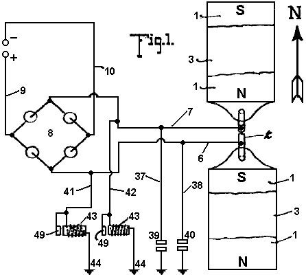
Fig.1 is a plan view of an apparatus embodying the features of the present invention, the arrow accompanying the figure indicating substantially the geographical north, parts of this figure are diagrammatic.
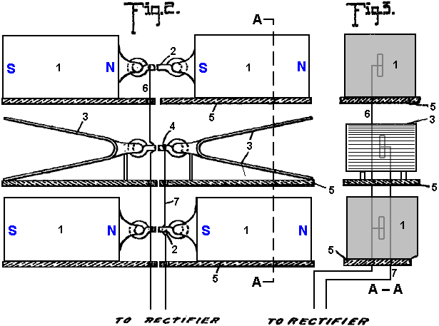
Fig.2 is a view is side elevation of the parts seen in plan in Fig.1
Fig.3 is a vertical section taken on the plane indicated by the line A--A of Fig.2.
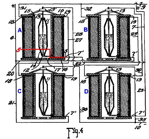
Fig.4 is a detail view, partly in elevation and partly in section, showing the connections of the converter and intensifier.
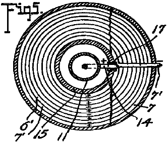
Fig.5 is a transverse section taken on the planes indicated by line 5-5 of Fig.4, looking downwards.
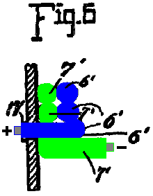
Fig.6 is an enlarged detail fragmentary section illustrating the parts at the junction of the conductors and one of the intensifiers.
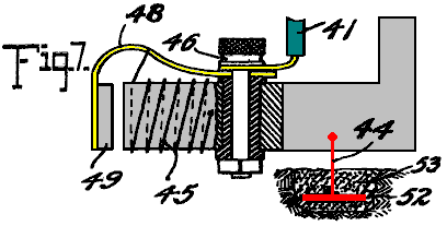
Fig.7 is an enlarged detail view partly in elevation and partly in section of one of the automatic cut-outs
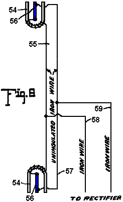
Fig.8 is a diagrammatic view of one of the simplest forms of embodiment of the invention.
Referring to the drawing by numerals, 1,1 indicates magnets connected by a magnetic substance 2, preferably an iron wire. The magnets 1 are arranged in pairs, one pair being spaced beneath the other, and interposed between the magnets are zinc plates 3,3 connected by an iron wire conductor 4. Suitable insulating supports 5 are arranged for sustaining the respective magnets 1 and plates 3,3. Each plate 3 is preferably bent substantially into V form, as clearly seen in Fig.1, and the V of one of the plates opens or faces toward the North and the V of the other plate to the South. I have determined by experimentation that it is essential that the plates 3 be disposed substantially North and South with their flat faces approximately parallel to the adjacent faces of the co-operating magnets, although by experience I have not discovered any material difference in the current obtained when the plates are disposed slightly to one side of North and South, as for instance when the plates are disposed slightly to one side of North and South, as for instance when disposed in the line of the magnetic polarity of the earth. The same is true with respect to the magnets 1, the said magnets being disposed substantially North and South for operative purposes, although I find that it is immaterial whether the North pole of one of the magnets is disposed to the North and the South pole to the South, or vice versa, and it is my conviction from experience that it is essential to have the magnets of each pair connected by magnetic material so that the magnets substantially become one with a pole exposed to the North and a pole exposed to the South.
In Fig.1, I have indicated in full lines by the letters 8 and N the respective polarities of the magnets 1, and have indicated in dotted lines the other pole of those magnets when the connection 2 is severed. I have found that the magnets and zinc plates operate to produce, (whether by collection or generation I am not certain), electrical currents when disposed substantially North and South, but when disposed substantially East and West, no such currents are produced. I also find that the question of elevation is by no means vital, but it is true that more efficient results are obtained by placing the zincs and magnets on elevated supports. I furthermore find from tests, that it is possible to obtain currents from the apparatus with the zincs and magnets disposed in a building or otherwise enclosed, although more efficient results are obtained by having them located in the open.
While in Figures 1, 2, and 3, I have shown the magnets and the zinc plates as superimposed, it will be apparent, as described in detail below, that these elements may be repositioned in horizontal planes, and substantially the same results will be secured. Furthermore, the magnets 1 with the interposed zincs 3, as shown in Figures 1, 2 and 3 merely represent a unit which may be repeated either horizontally or vertically for increasing the current supply, and when the unit is repeated the zinc plates are arranged alternating with the magnets throughout the entire series as indicated below.
A conductor 6 is connected in multiple with the conductors 2 and a conductor 7 is connected with conductor 4, the conductor 6 extending to one terminal of a rectifier which I have indicated by the general reference character 8, and the conductor 7 extending to the other terminal of the rectifier. The rectifier as seen in the diagram Fig.1 may assume any of several well known embodiments of the electrical valve type and may consist of four asymmetric cells or Cooper-Hewitt mercury vapour lamps connected as indicated in Fig.1 for permitting communication of the positive impulses from the conductor 6 only to the line conductor 9 and the negative impulses from conductor 6 on only to the line conductor 10. The current from this rectifier may be delivered through the conductors 9 and 10 to any suitable source for consumption.
While the said rectifier 8 may consist of any of the known types, as above outlined, it preferably consists of a specially constructed rectifier which also has the capacity of intensifying the current and comprises specifically the elements shown in detail in Figures 4, 5, and 6 wherein I have disclosed the detail wiring of the rectifier when composed of four of the rectifying and intensify in elements instead of asymmetric cells or simple mercury vapour valves. As each of these structures is an exact embodiment of all the others, one only will be described, and the description will apply to all. The rectifying element of each construction consists of a mercury tube 11 which is preferably formed of glass or other suitable material, and comprises a cylinder having its end portions tapered and each terminating in an insulating plug or stopper 12. Through the upper stopper 12 is extended the electrode 13 which extends well into the tube and preferably about one-half its length, to a point adjacent the inner end of an opposing electrode 14 which latter electrode extends from there down through the insulation 12 at the lower end of the tube. The tube 11 is supplied with mercury and is adapted to operate on the principle of the mercury vapour lamp, serving to rectify current by checking back impulses of one sign and permitting passage of impulses of the other.
To avoid the necessity for utilising a starter, as is common with the lamp type of electrical valve, the supply of mercury within the tube may be sufficient to contact with the lower end of the electrode 13 when current is not being supplied, so that as soon as current is passed from one electrode to the other sufficiently for volatilising that portion of the mercury immediately adjacent the lower end of electrode 13, the structure begins its operation as a rectifier. The tube 11 is surrounded by a tube 15 which is preferably spaced from tube 11 sufficiently for allowing atmospheric or other cooling circulation to pass the tube 11. In some instances, it may be desirable to cool the tube 11 by a surrounding body of liquid, as mentioned below. The tube 15 may be of insulating material but I find efficient results attained by the employment of a steel tube, and fixed to the ends of the of the tube are insulating disks 16, 16 forming a spool on which are wound twin wires 6’ and 7’, the wire 6’ being connected at the inner helix of the coil with the outer end of the electrode 14, the lower portion of said electrode being extended to one side of the tube 11 and passed through an insulating sleeve 17 extending through the tube 15, and at its outer end merging into the adjacent end of the wire 6’. The wire 7’ extends directly from the outer portion of the spool through the several helices to a point adjacent to the junction of the electrode 14 with wire 6’ and thence continues parallel to the wire throughout the coil, the wire 6’ ending in a terminal 18 and the wire 7’ ending in a terminal 19.
For the sake of convenience of description and of tracing the circuits, each of the apparatus just above described and herein known as an intensifier and rectifier will be mentioned as A, B, C and D, respectively. Conductor 6 is formed with branches 20 and 21 and conductor 7 is formed with similar branches 22 and 23. Branch 20 from conductor 6 connects with conductor 7’ of intensifier B and branch 21 of conductor 6 connects with the conductor 7’ of intensifier C, while branch 22 of conductor 7 of intensifier C, while branch 22 of conductor 7 connects with conductor 7’ of intensifier D. A conductor 27 is connected to terminal 19 of intensifier A and extends to and is connected with the terminal 18 of intensifier C, and a conductor 7 connects with conductor 7’ of intensifier D. A conductor 27 is connected to terminal 19 of intensifier A, and extends to and is connected to terminal 18 of intensifier C, and a conductor 28 is connected to the terminal 19 of intensifier C and extends from the terminal 19 of intensifier B to the terminal 18 of intensifier D to electrode 13 of intensifier B. Each electrode 13 is supported on a spider 13’ resting on the upper disk 16 of the respective intensifier. Conductors 31 and 32 are connected to the terminals 18 of intensifiers A and B and are united to form the positive line wire 9 which co-operates with the negative line wire 10 and extends to any suitable point of consumption. The line wire 10 is provided with branches 35 and 36 extending to the electrodes 13 of intensifiers C and D to complete the negative side of the circuit.
Thus it will be seen that alternating currents produced in the wires 6 and 7 will be rectified and delivered in the form of a direct current through the line wires 9 and 10, and I find by experiment that the wires 6 and 7 should be of iron, preferably soft, and may of course be insulated, the other wiring not specified as iron being of copper or other suitable material.
In carrying out the operation as stated, the circuits may be traced as follows: A positive impulse starting at the zincs 3 is directed along conductor 7 to branch 23 to conductor 7’ and the winding of the rectifier of intensifier B through the rectifier to the conductor 6’, through its winding to the contact 18, conductor 32 and to the line wire 9. The next, or negative, impulse directed along conductor 7 cannot find its way along branch 23 and the circuit just above traced because it cannot pass across the rectifier of intensifier B but instead the negative impulse passes along conductor 22 to conductor 7 of intensifier A and its winding to the contact 19 and to conductor 27 to contact 18 of intensifier C, to the winding of the wire 6’ thereof to the electrode 14 through the rectifier to the of the electrode 13 and conductor of intensifier A, electrode 14 thereof and conductor 6’ to contact 18 and wire 31 to line wire 9.
Obviously the positive impulse cannot pass along the wire 20 because of its inverse approach to the rectifier of intensifier B. The next impulse or negative impulse delivered to conductor 6 cannot pass along conductor 21 because of its connection with electrode 13 of the rectifier of intensifier A, but instead passes along conductor 20 to the wire 7’ and its winding forming part of intensifier B to the contact 19 and conductor 29 to contact 18 and the winding of wire 6’ of intensifier D to the electrode 14 and through the rectifier to the electrode 13 and conductor 35 to line wire 10. Thus the current is rectified and all positive impulses directed along one line and all negative impulses along the other lie s that the potential difference between the two lines will be maximum for the given current of the alternating circuit. It is, of course, apparent that a less number of intensifiers with their accompanying rectifier elements may be employed with a sacrifice of the impulses which are checked back from a lack of ability to pass the respective rectifier elements, and in fact I have secured efficient results by the use of a single intensifier with its rectifier elements, as shown below.
Grounding conductors 37 and 38 are connected respectively with the conductors 6 and 7 and are provided with the ordinary lightning arresters 39 and 40 respectively for protecting the circuit against high tension static charges.
Conductors 41 and 42 are connected respectively with the conductors 6 and 7 and each connects with an automatic cut-out 43 which is grounded as at 4. Each of the automatic cut-outs is exactly like the other and one of the these is shown in detail in Fig.7 and comprises the inductive resistance 45 provided with an insulated binding post 46 with which the respective conductor 6 or 7 is connected, the post also supporting a spring 48 which sustains an armature 49 adjacent to the core of the resistance 45. The helix of resistance 45 is connected preferably through the spring to the binding post at one end and at the other end is grounded on the core of the resistance, the core being grounded by ground conductor 44 which extends to the metallic plate 52 embedded in moist carbon or other inductive material buried in the earth. Each of the conductors 41, 42 and 44 is of iron, and in this connection I wish it understood that where I state the specific substance I am able to verify the accuracy of the statement by the results of tests which I have made, but of course I wish to include along with such substances all equivalents, as for instance, where iron is mentioned its by-products, such as steel, and its equivalents such as nickel and other magnetic substances are intended to be understood.
The cut-out apparatus seen in detail in Fig.7 is employed particularly for insuring against high voltage currents, it being obvious from the structure shown that when potential rises beyond the limit established by the tension of the spring sustaining the armature 40, the armature will be moved to a position contacting with the core of the cut-out device and thereby directly close the ground connection for line wire 41 with conductor 44, eliminating the resistance of winding 45 and allowing the high voltage current to be discharged to the ground. Immediately upon such discharge the winding 45 losing its current will allow the core to become demagnetised and release the armature 49 whereby the ground connection is substantially broken leaving only the connection through the winding 45 the resistance of which is sufficient for insuring against loss of low voltage current.
In Fig.8 I have illustrated an apparatus which though apparently primitive in construction and arrangement shows the first successful embodiment which I produced in the course of discovery of the present invention, and it will be observed that the essential features of the invention are shown there. The structure shown in the figure consists of horseshoe magnets 54, 55, one facing North and the other South, that is, each opening in the respective directions indicated and the two being connected by an iron wire 55 which is uninsulated and wrapped about the respective magnets each end portion of the wire 55 being extended from the respective magnets to and connected with, as by being soldered to, a zinc plate 56, there being a plate 56 for each magnet and each plate being arranged longitudinally substantially parallel with the legs of the magnet and with the faces of the plate exposed toward the respective legs of the magnet, the plate being thus arranged endwise toward the North and South. An iron wire 57 connects the plates 56, the ends of the wire being preferably connected adjacent the outer ends of the plates but from experiment I find that the wire may be connected at practically any point to the plate. Wires 58 and 59 are connected respectively with the wires 55 and 57 and supply an alternating current at a comparatively low voltage, and to control such current the wires 58 and 59 may be extended to a rectifier or combined rectifier and intensifier, as discussed above.
The tests which I have found successful with the apparatus seen in Fig.8 were carried out by the employment first of horseshoe magnets approximately 4 inches in length, the bar comprising the horseshoe being about one inch square, the zincs being dimensioned proportionately and from this apparatus with the employment of a single intensifier and rectifier, as above stated, I was able to obtain a constant output of 8 volts.
It should be obvious that the magnets forming one of the electrodes of this apparatus may be permanent or may be electromagnets, or a combination of the two.
While the magnets mentioned throughout the above may be formed of any magnetic substance, I find the best results obtained by the employment of the nickel chrome steel.
While the successful operation of the various devices which I have constructed embodying the present invention have not enabled me to arrive definitely and positively at fixed conclusion relative to the principles and theories of operation and the source from which current is supplied, I wish it to be understood that I consider myself as the first inventor of the general type described above, capable of producing commercially serviceable electricity, for which reason my claims hereinafter appended contemplate that I may utilise a wide range of equivalents so far as concerns details of construction suggested as preferably employed.
The current which I am able to obtain is dynamic in the sense that it is not static and its production is accomplished without chemical or mechanical action either incident to the actual chemical or mechanical motion or incident to changing caloric conditions so that the elimination of necessity for the use of chemical or mechanical action is to be considered as including the elimination of the necessity for the use of heat or varying degrees thereof.
PAULO and
ALEXANDRA CORREA
Pat. Application
ENERGY
CONVERSION SYSTEMS
This patent application shows the details of devices which can produce ordinary electricity from Tesla longitudinal waves. If these claims are correct (and there does not appear to be the slightest reason for believing that they are not), then implementations of this patent application are capable of producing free electrical power and the importance of this information is enormous.
ABSTRACT
This invention relates to apparatus for the conversion of mass-free energy into electrical or kinetic energy, which uses in its preferred form a transmitter and a receiver both incorporating Tesla coils, the distal ends of whose secondary windings are co-resonant and connected to plates of a chamber, preferably evacuated or filled with water, such that energy radiated by the transmitter may be picked up by the receiver, the receiver preferably further including a pulsed plasma reactor driven by the receiver coil and a split phase motor driven by the reactor. Preferably the reactor operates in pulsed abnormal gas discharge mode, and the motor is an inertially dampened drag motor. The invention also extends to apparatus in which an otherwise driven plasma reactor operating in pulsed abnormal gas discharge mode in turn used to drive an inertially dampened drag motor.
DESCRIPTION
This is a continuation of application Ser. No. 09/907,823, filed Jul. 19, 2001.
FIELD OF
THE INVENTION
This invention relates to systems for the conversion of energy, inter alia in the form of what we will refer to for convenience as Tesla waves (see below), to conventional electrical energy.
BACKGROUND
OF THE INVENTION
Energy
converters that are fed by local or environmental energy are usually explained
by taking recourse to the notion that they convert zero point electromagnetic
radiation (ZPE) to electric energy. The
ZPE theories have gained a life of their own, as T. Kuhn has pointed out (in
his "Black Body Theory and the Quantum"), after emerging from
Planck's second theory, specifically from the term ![]() in the new formula for oscillator energy. In 1913, Einstein and Stern suggested that
motional frequencies contributing to specific heat fell into two
categories--those that were independent of temperature and those that were not (e.g.
rotational energy), leading them to conclude that zero-point energy on the
order of
in the new formula for oscillator energy. In 1913, Einstein and Stern suggested that
motional frequencies contributing to specific heat fell into two
categories--those that were independent of temperature and those that were not (e.g.
rotational energy), leading them to conclude that zero-point energy on the
order of ![]() was most likely. In the second part of their paper, however,
they provided a derivation of Planck's Law without taking recourse to
discontinuity, by assuming that the value of the ZPE was simply ha. It is worth noting that Einstein had already
in 1905 ("Erzeugung und Verwandlung des Lichtes betreffenden heuristichen
Gesichtspunkt",Ann. d. Phys, 17, 132) framed the problem of discontinuity,
even if only heuristically, as one of placing limits upon the infinite energy
of the vacuum state raised by the Rayleigh-Jeans dispersion law. According to Einstein, the Rayleigh-Jeans law
would result in an impossibility, the existence of infinite energy in the
radiation field, and this was precisely incompatible with Planck's discovery -
which suggested instead, that at high frequencies the entropy of waves was
replaced by the entropy of particles.
Einstein, therefore, could only hope for a stochastic validation of
Maxwell's equations at high frequencies "by supposing that electromagnetic
theory yields correct time-average values of field quantities", and went
on to assert that the vibration-energy of high frequency resonators is
exclusively discontinuous (integral multiples of
was most likely. In the second part of their paper, however,
they provided a derivation of Planck's Law without taking recourse to
discontinuity, by assuming that the value of the ZPE was simply ha. It is worth noting that Einstein had already
in 1905 ("Erzeugung und Verwandlung des Lichtes betreffenden heuristichen
Gesichtspunkt",Ann. d. Phys, 17, 132) framed the problem of discontinuity,
even if only heuristically, as one of placing limits upon the infinite energy
of the vacuum state raised by the Rayleigh-Jeans dispersion law. According to Einstein, the Rayleigh-Jeans law
would result in an impossibility, the existence of infinite energy in the
radiation field, and this was precisely incompatible with Planck's discovery -
which suggested instead, that at high frequencies the entropy of waves was
replaced by the entropy of particles.
Einstein, therefore, could only hope for a stochastic validation of
Maxwell's equations at high frequencies "by supposing that electromagnetic
theory yields correct time-average values of field quantities", and went
on to assert that the vibration-energy of high frequency resonators is
exclusively discontinuous (integral multiples of ![]() ).
).
Since then, ZPE theories have gone on a course independent from Planck's second theory. The more recent root of modern ZPE theories stems from the work of H. Casimir who, in 1948, apparently showed the existence of a force acting between two uncharged parallel plates. Fundamentally the Casimir effect is predicated upon the existence of a background field of energy permeating even the “vacuum”, which exerts a radiation pressure, homogeneously and from all directions in space, on every body bathed in it. Given two bodies or particles in proximity, they shield one another from this background radiation spectrum along the axis (i.e. the shortest distance) of their coupling, such that the radiation pressure on the facing surfaces of the two objects would be less than the radiation pressure experienced by all other surfaces and coming from all other directions in space. Under these conditions, the two objects are effectively pushed towards one another as if by an attractive force. As the distance separating the two objects diminishes, the force pushing them together increases until they collapse one on to the other. In this sense, the Casimir effect would be the macroscopic analogy of the microscopic van der Waals forces of attraction responsible for such dipole-dipole interactions as hydrogen bonding. However, it is worth noting that the van der Waals force is said to tend to establish its normal radius, or the optimal distance between dipoles, as the distance where the greatest attractive force is exerted, beyond which the van der Waals forces of nuclear and electronic repulsion overtake the attraction force.
Subsequently, another Dutch physicist, M. Sparnaay, demonstrated that the Casimir force did not arise from thermal radiation and, in 1958, went on to attribute this force to the differential of radiation pressure between the ZPE radiation from the vacuum state surrounding the plates and the ZPE radiation present in the space between them. Sparnaay's proposal is that a classical, non-quantal, isotropic and ubiquitous electromagnetic zero-point energy exists in the vacuum, and even at a temperature of absolute zero. It is further assumed that since the ZPE radiation is invariant with respect to the Lorentz transformations, it obeys the rule that the intensity of its radiation is proportional to the cube of the frequency, resulting in an infinite energy density for its radiation spectrum.
What appeared to be the virtue of this reformulated theory was the notion that the vacuum no longer figured as pure space empty of energy, but rather as a space exposed to constantly fluctuating “fields of electromagnetic energy”.
Puthoff has utilised the isomorphism between van der Waals and Casimir forces to put forth the zero-point (ZP) energy theory of gravity, based on the interpretation that the virtual electromagnetic ZP field spectrum predicted by quantum electrodynamics (QED) is functionally equivalent to an actual vacuum state defined as a background of classical or Maxwellian electromagnetic radiation of random phases, and thus can be treated by stochastic electrodynamics (SED). Whereas in QED, the quanta are taken as virtual entities and the infinite energy of the vacuum has no physical reality, for SED, the ZPE spectrum results from the distortion of a real physical field and does not require particle creation. Gravity then, could be seen as only the macroscopic manifestation of the Casimir force.
We do not dispute the fact that even in space-absent matter, there is radiant energy present which is not of a thermal nature. But we claim that this energy is not electromagnetic, nor is its energy spectrum-infinite. That this is so, stems not just from our opinion that it is high time that Einstein's heuristic hypothesis should be taken as literally factual - in the dual sense that all electromagnetic energy is photon energy and all photons are local productions, but above all from the fact that it is apparent, from the experiments of Wang and his colleagues (Wang, Li, Kuzmich, A & Dogariu, A. "Gain-assisted superluminal light propagation", Nature 406; #6793; 277), that the photon stimulus can propagate at supraluminal speeds and lies therefore well outside of any scope of electromagnetic theory, be this Maxwell's classical approach taken up by ZPE theories, or Einstein's special relativistic phenomenology of Maxwell's theory. The fact is, that if the light stimulus can propagate at speeds greater than those of light, then what propagates is not light at all, and thus not energy configured electromagnetically. Light is solely a local production of photons in response to the propagation of a stimulus that itself is not electromagnetic.
It is critical to understand that the implication from this, that - aside from local electromagnetic radiation and from thermal radiation associated with the motions of molecules (thermo-mechanical energy), there is at least one other form of energy radiation which is everywhere present, even in space-absent matter. Undoubtedly, it is that energy which prevents any attainment of absolute zero, for any possible local outpumping of heat is matched by an immediate local conversion of some of this energy into a minimum thermal radiation required by the manifolds of Space and Time. Undoubtedly also, this radiation is ubiquitous and not subject to relativistic transformations (i.e. it is Lorentz invariant). What it is not, is electromagnetic radiation consisting of randomistic phases of transverse waves.
To understand this properly, one must summarise the differences from existing ZPE theories - and all these differences come down to the fact that this energy, which is neither electromagnetic nor thermal per se, (and is certainly not merely thermo-mechanical), has nevertheless identifiable characteristics both distributed across sub-types or variants and also common to all of them.
Essentially, the first sub-type or variant consists of longitudinal mass-free waves which deploy electric energy. They could well be called Tesla waves, since Tesla-type transformers can indeed be shown experimentally to radiate mass-free electric energy, in the form of longitudinal magnetic and electric waves having properties not reducible to photon energy nor to “electromagnetic waves”, and having speeds of displacement which can be much greater than the limit c for all strictly electromagnetic interactions.
One may well denote the second sub-type by the designation of mass-free thermal radiation, since it contributes to temperature changes - and, as obviously indicated by the impossibility of reaching an absolute zero of temperature, this contribution occurs independently of the presence of matter, or mass-energy, in Space. In other words, not all thermal radiation can be reduced to vibration, rotation and translation (drift motion) of molecules, i.e. to thermomechanical energy, because the properties of pressure and volume which determine temperature and affect matter, appear indeed to a great extent to be independent from matter, a fact which itself is responsible for the observed catastrophic and unexpected phase changes of matter and has required to this day the insufficient explanation offered semi-empirically by the Van der Waals Force Law.
Finally, the third sub-type may be designated latent mass-free energy radiation - since it deploys neither charge, nor thermal or baroscopic effects, and yet it is responsible for “true latent heat” or for the “intrinsic potential energy” of a molecule. It is also responsible for the kineto-regenerative phenomenon whereby an electroscope performs a variable charge-mediated work against the local gravitational field.
The common
characteristic of all three sub-types of mass-free energy radiation is that
they share the same non-classical fine structure, written as follows for any
energy unit, where c is any speed of
light wave function, and the wavelength ![]() and wave function W are interconnected as a function of the
physical quality of the energy field under consideration:
and wave function W are interconnected as a function of the
physical quality of the energy field under consideration: ![]()
In the instance of longitudinal electric radiation, this takes on the directly quantifiable form:
![]()
where:
Wv is the voltage-equivalent wave function corresponding to V,
Pe constitutes the linear momentum corresponding to the conventional q or e,
h is the Planck constant,
![]() is the Duane-Hunt constant expressed as a
wavelength,
is the Duane-Hunt constant expressed as a
wavelength,
![]() is a wavelength constant; and the sign
is a wavelength constant; and the sign
![]() signifies exact equality between an expression
in the conventional dimensions of length, mass and time, and an expression in
length and time dimensions alone.
signifies exact equality between an expression
in the conventional dimensions of length, mass and time, and an expression in
length and time dimensions alone.
In the instance of mass-free thermal radiation (contributing to temperature changes), the transformation obeys Boltzmann's rule (k is now Boltzmann's constant and T is Kelvin-scale temperature):
![]()
and in the third instance - of latent mass-free radiation, the transformation obeys the rule:
![]()
where ![]() and
and ![]() are
frequency functions,
are
frequency functions, ![]() being a
specific gravitational frequency term, and
being a
specific gravitational frequency term, and ![]() being defined as equal to
being defined as equal to ![]() and
and ![]() has the value of
has the value of ![]()
If the
electric variant of mass-free radiation has a direct quantum equivalence, via
the Duane-Hunt Law, none of the three primary aether energy variants possess
either the classic form of electromagnetic energy which requires square
superimposition of speed of light wave functions c, as c2, or the quantum form of energy,
requiring E = ![]() . The critical first step in the right
direction may well be attributed to Dr. W. Reich, as it regards the fact that
mass-free energy couples two unequal wave functions, only one of which is
electromagnetic and abides by the limit c. We then unravelled the threefold structure
described above, and further showed that, in the case of longitudinal electric
waves, the postulated equivalence
. The critical first step in the right
direction may well be attributed to Dr. W. Reich, as it regards the fact that
mass-free energy couples two unequal wave functions, only one of which is
electromagnetic and abides by the limit c. We then unravelled the threefold structure
described above, and further showed that, in the case of longitudinal electric
waves, the postulated equivalence ![]() is merely phenomenological, as these waves are
not restricted by the function c in
their conveying of electric charge across space. It can further be demonstrated that all
black-body photons are bound by an upper frequency limit (64 x 1014 Hz), above
which only ionising photons are produced, and that all black-body photons arise
precisely from the interaction of mass-free electric radiation with molecules
of matter (including light leptons), whereby the energy of that radiation is
locally converted into photon or electromagnetic radiation. In other words, all non-ionising
electromagnetic energy appears to be secondary energy which results locally
from the interaction of matter with mass-free electric energy. It cannot therefore consist of the primary
energy that is present in the vacuum, an energy that is neither virtual nor
electromagnetic, but actual and concrete in its electric, thermal and
antigravitic manifestations. Lastly,
gravitational energy, being either the potential or the kinetic energy
responsible for the force of attraction between units of matter, is a
manifestation that also requires, much as electromagnetic radiation does,
coupling of mass-free energy to matter or to mass-energy.
is merely phenomenological, as these waves are
not restricted by the function c in
their conveying of electric charge across space. It can further be demonstrated that all
black-body photons are bound by an upper frequency limit (64 x 1014 Hz), above
which only ionising photons are produced, and that all black-body photons arise
precisely from the interaction of mass-free electric radiation with molecules
of matter (including light leptons), whereby the energy of that radiation is
locally converted into photon or electromagnetic radiation. In other words, all non-ionising
electromagnetic energy appears to be secondary energy which results locally
from the interaction of matter with mass-free electric energy. It cannot therefore consist of the primary
energy that is present in the vacuum, an energy that is neither virtual nor
electromagnetic, but actual and concrete in its electric, thermal and
antigravitic manifestations. Lastly,
gravitational energy, being either the potential or the kinetic energy
responsible for the force of attraction between units of matter, is a
manifestation that also requires, much as electromagnetic radiation does,
coupling of mass-free energy to matter or to mass-energy.
The Tesla coil is a generator of a mass-free electric energy flux which it transmits both by conduction through the atmosphere and by conduction through the ground. Tesla thought it did just that, but it has been since regarded instead (because of Maxwell, Hertz and Marconi) as a transmitter of electromagnetic energy. The transmitter operates by a consumption of mass-bound electric power in the primary, and by induction it generates in the coupled secondary two electric fluxes, one mass-bound in the coil conductor, and the other mass-free in the body of the solenoid. Tesla also proposed and demonstrated a receiver for the mass-free energy flux in the form of a second Tesla coil resonant with the first. The receiver coil must be identical and tuned to the transmitter coil; the capacitance of the antenna plate must match that of the transmitter plate; both transmitter and receiver coils must be grounded; and the receiver coil input and output must be unipolar, as if the coil were wired in series.
The generators
of mass-free energy with which we are concerned, provide current pulses
associated with a dampened wave (DW) oscillation of much higher frequency than
the pulse repetition frequency. A
particular problem in recovering the mass-free energy content of such pulses is
provided by the dampened wave oscillations. Although in our
In nineteenth century motor engineering terminology, dynamos capable of producing direct current by continuous homopolar induction were known as “unipolar” generators. The term “unipolar induction” appears to have originated with W. Weber, to designate homopolar machines where the conductor moves continuously to cut the magnetic lines of one kind of magnetic pole only, and thus require sliding contacts to collect the generated current. Faraday's rotating copper disc apparatus was, in this sense, a homopolar generator when the disc was driven manually, or a homopolar motor when the current was provided to it. Where the rotating conductor continuously cuts the magnetic field of alternatingly opposite magnetic poles, the operation of a machine, whether a generator or a motor, is said to be “heteropolar”. Unipolar machines went on to have a life of their own in the form of low voltage and high current DC generators - from Faraday, through Plucker, Varley, Siemens, Ferraris, Hummel, to Lord Kelvin, Pancinoti, Tesla and others - almost exclusively in the form of disc dynamos, but some having wound rotors.
In Mordey's alternator, and in so-called “inductor alternators”, however, homopolar generators were employed to obtain alternating currents, with the use of rotors wound back and forth across the field. Use of smooth, unwound rotors in AC induction motors (as opposed to AC synchronous motors, such as hysteresis motors) was a later development than homopolar dynamos. By 1888, Tesla and Ferraris amongst still others, had independently produced rotating magnetic fields in a motor, by employing two separate alternate currents with the same frequency but different phase. Single phase alternate current motors were developed later, and split-phase motors were developed last. Ferraris (Ferraris, G (1888) "Rotazioni elettrodynamiche", Turin Acad, March issue.) proposed the elementary theory of the 2-phase motor, where the current induced in the rotor is proportional to the slip (the difference between-the angular velocity of the magnetic field and that of the rotating cylinder), and the power of the motor is proportional to both the slip and the velocity of the rotor.
If an iron rotor is placed within the rotating magnetic field of a 2-phase stator, it will be set in rotation, but not synchronously, given that it is always attracted to the moving magnetic poles with a lag. But if an aluminium or copper rotor is used instead, it gets “dragged” around by the rotating stator field because of the eddy currents induced in it. If the aluminium or copper rotor were to rotate synchronously with the stator magnetic field, there would be no induced eddy currents and thus no motor action would result. The motor action depends, in this instance, upon the presence of asynchronous slip, since the function of the latter is to sustain the induction of those currents in the rotor that are responsible for the motor action of the dragged rotor. This then is the origin of the term “AC drag motors”. Once the drag rotor evolved from a cylinder to a hollow cup, they earned the epithet of “drag-cup motors”. Later, already in the 20th century, the cups were fitted over a central stator member, and the sleeve rotor 2-phase servo motor was born.
Tesla knew that impulse currents as well as CW (constant wave) sinusoidal currents could be used to drive AC motors. Regarding his invention of a hysteresis motor (which he called a “magnetic lag motor”), he stated: " . . . pulsatory as well as an alternating current might be used to drive these motors . . . " (Martin, T C (1894) "The inventions, researches and writings of Nikola Tesla", Chapter XII, p. 68). In his search for efficient utilisation of the high frequency DW (dampened wave) impulse currents of his induction coils, Tesla began by employing an AC disc induction motor as shown in Fig.17 of his famous 1892 address (Tesla, N (1892) "Experiments with alternate currents of high potential and high frequency", in "Nikola Tesla Lectures", 1956, Beograd, pp. L-70-71). This consisted of a copper or aluminium disc mounted vertically along the longitudinal axis of an iron core on which was wound a single motor coil which was series wired to the distal terminal of an induction coil at one end, and to a large suspended and insulated metal plate at the other. What was new about this was the implementation of an AC disc induction motor drive, where the exciting current travelled directly through the winding with just a unipolar connection to the coil secondary (under certain conditions, even the series connection to the plate could be removed, or replaced with a direct connection to the experimenter's body): "What I wish to show you is that this motor rotates with one single connection between it and the generator" (Tesla, N. (1892), op. cit., L-70, Tesla's emphasis). Indeed, he had just made a critical discovery that, unlike in the case of mass-bound charge where current flow requires depolarisation of a bipolar tension, mass-free charge engages current flow unipolarly as a mere matter of proper phase synchronisation:
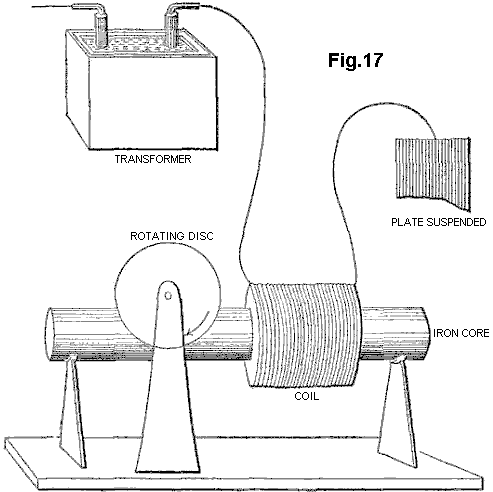
Tesla thought that his motor was particularly adequate to respond to windings which had “high-self-induction”, such as a single coil wound on an iron core. The basis of this self-induction is the magnetic reaction of a circuit, or an element of a circuit - an inductor - whereby it chokes, dims or dampens the amplitude of electric waves and retards their phase.
For the motor to respond to still higher frequencies, one needed to wind over the primary motor winding, a partial overlap secondary, closed through a capacitor, since "it is not at all easy to obtain rotation with excessive frequencies, as the secondary cuts off almost completely the lines of the primary" (Idem, L-71.).
Tesla stated that "an additional feature of interest about this motor" was that one could run it with a single connection to the earth ground, although in fact one end of the motor primary coil had to remain connected to the large, suspended metal plate, placed so as to receive or be bathed by "an alternating electrostatic field", while the other end was taken to ground. Thus Tesla had an ordinary induction coil that transmitted this "alternating electrostatic field", an untuned Tesla antenna receiving this "field", and a receiver circuit comprising his iron-core wound motor primary, a closely coupled, capacitatively closed secondary, and the coupled non-ferromagnetic disc rotor. Eventually, in his power transmission system, he would replace this transmitter with a Tesla coil, and place an identical receiving coil at the receiving end, to tune both systems and bring them into resonance. But his motor remained undeveloped, and so did the entire receiver system.
Tesla returned to this subject a year later, saying "on a former occasion I have described a simple form of motor comprising a single exciting coil, an iron core and disc" (Tesla, N (1893) "On light and other high frequency phenomena", in "Nikola Tesla Lectures", 1956, Beograd, pp. L-130, and L-131 with respect to Fig.16-II). He describes how he developed a variety of ways to operate such AC motors unipolarly from an induction transformer, and as well other arrangements for "operating a certain class of alternating motors founded on the action of currents of differing phase". Here, the connection to the induction transformer is altered so that the motor primary is driven from the coarse secondary of a transformer, whose finer primary is coupled, at one end, directly and with a single wire to the Tesla secondary, and at the other left unconnected. On this occasion, Tesla mentions that such a motor has been called a “magnetic lag motor”, but that this expression (which, incidentally, he had himself applied to his own invention of magnetic hysteresis motors) is objected to by "those who attribute the rotation of the disc to eddy currents when the core is finally subdivided" (Tesla, N (1893), op. cit., p. L-130).
In none of the other motor solutions, 2-phase or split-phase, that he suggests as unipolar couplings to the secondary of an induction coil, does the non-ferromagnetic disc rotor motor again figure. But he returns to it a page later, and indirectly so, by first addressing the disadvantages of ferromagnetic rotors: "Very high frequencies are of course not practicable with motors on account of the necessity of employing iron cores. But one may use sudden discharges of low frequency and thus obtain certain advantages of high-frequency currents-without rendering the iron core entirely incapable of following the changes and without entailing a very great expenditure of energy in the core. I have found it quite practicable to operate, with such low frequency disruptive discharges of condensers, alternating-current motors."
In other words--whereas his experiments with constant wave (CW) alternating currents, and as well with high-voltage dampened wave (DW) impulses from induction coils, indicated the existence of an upper frequency limit to iron core motor performance, one might employ instead high-current, DW impulses - of high DW frequencies but low impulse rates - to move these motors quite efficiently. Then he adds "A certain class of [AC] motors which I advanced a few years ago, that contain closed secondary circuits, will rotate quite vigorously when the discharges are directed through the exciting coils. One reason that such a motor operates so well with these discharges is that the difference of phase between the primary and secondary currents is 90 degrees, which is generally not the case with harmonically rising and falling currents of low frequency. It might not be without interest to show an experiment with a simple motor of this kind, inasmuch as it is commonly thought that disruptive discharges are unsuitable for such purposes."
What he proposes next, forms the basis of modern residential and industrial AC electric power meters, the AC copper disc motor whose rotor turns on the window of these meters, propelled forward by the supply frequency. But instead of employing any such Constant Wave input, Tesla uses the disruptive discharges of capacitors, incipiently operating as current rectifiers. With the proper conditions, e.g. correct voltage from the generator, adequate current from the capacitor, optimum capacitance for the firing rate, and tuned spark-gap, to mention a few, Tesla found that the non-ferromagnetic disc rotor turned but with considerable effort. But this hardly compared to the results obtained with a high-frequency CW alternator, which could drive the disc "with a much smaller effort". In summary then, Tesla went as far as being the first to devise a motor driven by Tesla waves, that employed a non-ferromagnetic rotor, and whose arrangement encompassed both transmitter and receiver circuits. For this purpose, he employed a single-phase method in which the signal is fed unipolarly to the winding, placed in series with a plate capacitance.
Tesla also later proposed driving a similar single-phase non-ferromagnetic disc motor from bipolar capacitative discharges through an atmospheric spark-gap now placed in parallel with the main motor winding, and again simulating a split-phase by a closely-wound secondary which was closed by a capacitance.
As Tesla admits, the results of all his AC eddy current motor solutions were meagre and limited by current and frequency problems. Likewise, the two-phase arrangements proposed by Reich for his OR motor, involving a superimposition of the Dampened Waves of a first phase on a fixed Continuous Wave second phase, require an external power source and a pulse amplifier circuit, and failed to meet Reich's own requirements.
We have previously proposed the use of squirrel cage motors with capacitative splitting of phase to convert the Dampened Wave output of plasma pulsers, but once a Squirrel Cage is introduced, the dampening effect which the non-ferromagnetic copper cage exerts in being dragged by the revolving stator field, is counteracted by the ferromagnetic cylinder of laminated iron, in which the copper cage is embedded, working to diminish the slip and bring the rotor to near synchronism. This is, in all likelihood, what limits Squirrel Cage motors responding to the DC component of the Dampened Wave impulse, and thus be limited to respond to fluxes of mass-bound charges. Historically, as we shall see, the obvious advantage of the Squirrel Cage servo motors lay in the fact that, in particular for 2-phase applications, they were far more efficient at performing work without evolution of heat. Indeed, if the eddy currents in the non-ferromagnetic rotor are permitted to circulate in non-ordered form, the rotor material and stator will heat up rapidly and consume much power in that heating. This is in fact considered to be a weakness of AC non-ferromagnetic-rotor induction motors.
SUMMARY OF
THE INVENTION
The present invention is concerned with conversion to conventional electrical energy of the variants of mass-free energy radiation considered above, referred to for convenience as Tesla waves, mass-free thermal radiation and latent mass-free radiation. The first variant of such radiation was recognised, generated and at least partially disclosed by Tesla about a hundred years ago, although his work has been widely misinterpreted and also confused with his work on the transmission of radio or electromagnetic waves. The Tesla coil is a convenient generator of such radiation, and is used as such in many of the embodiments of our invention described below, but it should be clearly understood that our invention in its broadest sense is not restricted to the use of such a coil as a source of mass-free radiation and any natural or artificial source may be utilised. For example, the sun is a natural source of such radiation, although interaction with the atmosphere means that it is largely unavailable at the earth's surface, limiting applications to locations outside of the earth's atmosphere.
According to the invention, a device for the conversion of mass-free radiation into electrical or mechanical energy comprises a transmitter of mass-free electrical radiation having a dampened wave component, a receiver of such radiation tuned to resonance with the dampened wave frequency of the transmitter, a co-resonant output circuit coupled into and extracting electrical or kinetic energy from the receiver, and at least one structure defining a transmission cavity between the transmitter and the receiver, a full-wave rectifier in the co-resonant output circuit, and an oscillatory pulsed plasma discharge device incorporated in the co-resonant output circuit. The output circuit preferably comprises a full-wave rectifier presenting a capacitance to the receiver, or an electric motor, preferably a split-phase motor, presenting inductance to the receiver. The transmitter and receiver each preferably comprise a Tesla coil and/or an autogenous pulsed abnormal glow discharge device. The transmission cavity is preferably at least partially evacuated, and comprises spaced plates connected respectively to the farthest out poles of the secondaries of Tesla coils incorporated in the transmitter and receiver respectively, the plates being parallel or concentric. The structure defining the cavity may be immersed in ion-containing water. The split-phase motor is preferably an inertially-dampened AC drag motor.
The invention, and experiments demonstrating its basis, are described further below with reference to the accompanying drawings.
SHORT
DESCRIPTION OF THE DRAWINGS
Fig.1 is a schematic view of a Tesla coil connected to a full-wave rectifier to form an energy conversion device:
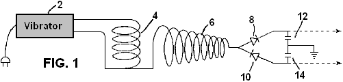
Fig.2 is a schematic view of a Tesla coil connected to a gold leaf electrometer:

Fig.3 to Fig.6 show alternative electrometer configurations:
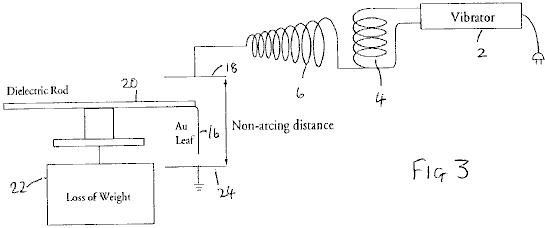

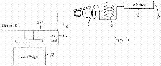
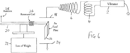
Fig.7 to Fig.11 show modifications of the circuit of Fig.1:
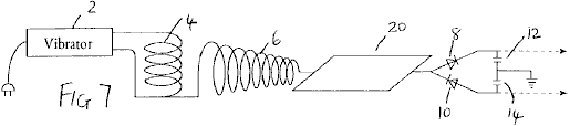
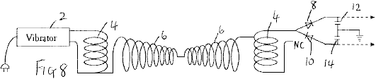
Fig.12 shows apparatus for investigating aspects of the experimental results obtained with the foregoing devices;
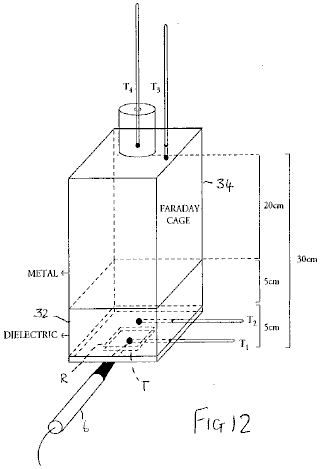
Fig.13 is a graph illustrating results obtained from the apparatus of Fig.12:
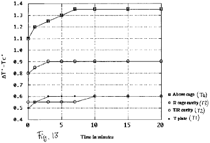
Fig.14 to Fig.17 show schematic diagrams of embodiments of energy conversion devices:
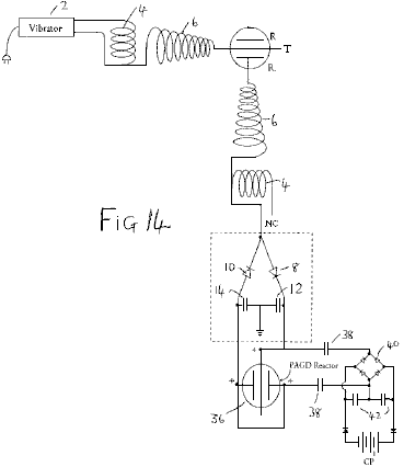
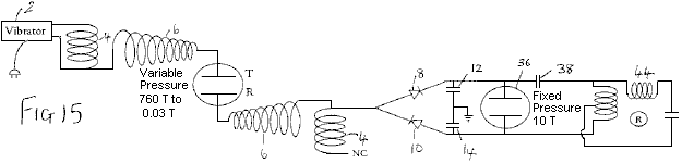
Fig.18 is a diagrammatic cross-section of an inertially dampened drag cup motor:
Fig.19 is a schematic diagram of a further embodiment of an energy conversion device incorporating such a motor:
DESCRIPTION
OF THE PREFERRED EMBODIMENTS
Based upon
observations of weight loss in metallic matter as induced by exposure to high
frequency alternating electric fields, we developed an experimental method to
optimise this-weight loss, and from this a device that treats the forces
causing weight loss as manifestations of intrinsic potential energy ![]() (or true "latent heat") of the
molecules of matter, and converts both "true latent heat" energy
present in the neighbourhood of a receiver, and "sensible" heat
induced within that receiver, into electric energy which can be used to drive a
motor, flywheel or charge batteries.
(or true "latent heat") of the
molecules of matter, and converts both "true latent heat" energy
present in the neighbourhood of a receiver, and "sensible" heat
induced within that receiver, into electric energy which can be used to drive a
motor, flywheel or charge batteries.
It is commonly believed that the output of the Tesla coil is ionising electromagnetic radiation. We have demonstrated that it is not, i.e. that it is neither electromagnetic radiation, nor ionising electromagnetic radiation. The output of an air-cored, sequentially-wound secondary, consists exclusively of electric energy: upon contact with the coil, a mass-bound AC current can be extracted at the resonant frequency, whilst across a non-sparking gap, mass-free AC-like electric wave radiation having the characteristics of longitudinal waves, can be intercepted anywhere in adjacent space. Accordingly, the radiation output from such coils is different to electromagnetic radiation.
The basic demonstration that the output of a Tesla coil does not consist of ionising radiation, is that it does not accelerate the spontaneous discharge rate of electroscopes, whether positively or negatively charged. In fact, in its immediate periphery, the coil only accelerates the spontaneous discharge rate of the negatively charged electroscope (i.e. the charge leakage rate), whereas it arrests the discharge of the positively charged electroscope (i.e. the charge seepage rate falls to zero). But this dual effect is not due to any emission of positive ions from the secondary, even if it can positively charge a discharged electroscope brought to its proximity. This charging effect is in fact an artifact, in that metals but not dielectrics are ready to lose their conduction and outer valence band electrons when exposed to the mass-free electric radiation of the coil.
This is simply demonstrated by the apparatus of Fig.1, in which the outer terminal of the secondary winding 6 of a Tesla coil having a primary winding 4 driven by a vibrator 2 is connected to the input of a full-wave voltage wave divider formed by diodes 8 and 10 and reservoir capacitors 12 and 14 (the same reference numerals are used for similar parts in subsequent diagrams). If the rectifiers employed are non-doped, then the coil appears to only charge the divider at the positive capacitance 10, but if doped rectifiers are employed, the coil will be observed to charge both capacitances equally. Whereas positive ionises can charge either doped or un-doped dividers positively, no positive ionise can charge a doped divider negatively, clearly demonstrating that the Tesla coil does not emit positive ions.
The basic demonstration that the output of a Tesla coil is not non-ionising electromagnetic radiation of high frequency, such as optical radiation, or of lower frequency, such as thermal photons, is also a simple one. Placement of a sensitive wide spectrum photoelectric cell (capable of detecting radiation to the limits of vacuum UV), wired in the traditional closed circuit manner from a battery supply, at any distance short of sparking from the outer terminal of the coil will show in the dark that the light output from the coil is negligible. This rules out optical radiation at high frequency. The demonstration that the sensible heat output from the Tesla coil is also negligible will be addressed below.
Our theory proposed the existence of physical processes whereby mass-free electric radiation can be converted into electromagnetic radiation. Such a process is at work whenever mass-free electric wave radiation interacts with electrons, such as those that remain in the valence bands of atoms. This mass-free electric energy interacts with charge carriers, such as electrons, to confer on them an electrokinetic energy which they shed in the form of light whenever that electrokinetic energy is dissociated from those carriers (e.g. by deceleration, collision or friction processes). Such a process is at work to a negligible extent in the coil itself and its usual terminal capacitance, hence the faint glow that can be seen to issue from it, but it can also be greatly amplified in the form of a corona discharge by connecting a large area plate to the output of the secondary, as Tesla himself did in his own experiments, and thus by increasing the capacitance of the coil system.
Now, what is interesting in this process is that, in the absence of virtually any I2R losses at the plate, and if the plate thus introduced is bent at the edges so that it has no pointed edges, or if it is in the form of a bowl, or in any other manner that precludes sparking at edges and specially corners, and thus enhances the corona discharge, any electroscope, whether negatively or positively charged, now brought close to the plate will show a tendency to arrest its spontaneous discharge rate. One might say that this is simply the result obtained in a Faraday cage which disperses charge on its outside and electrically insulates its interior, and indeed if an electroscope is placed inside a Faraday cage no amount of Tesla radiation on the outside of that cage, save direct sparking, adversely affects the leakage or seepage rate of the electroscope. In fact, since the effect of such a cage can be shown to be that of, by itself, inducing arrest of either spontaneous electroscopic discharge, this effect simply remains or is magnified when the cage is bathed by Tesla radiation. However, a cage constitutes an electrically isolated environment, whereas a plate with or without curved or bent edges does not. Furthermore, the change observed in the properties of the output radiation from a Tesla coil when certain metal plates or surfaces are directly connected to the outer terminal of the secondary, takes place whilst the capacitance of the coil is increased by the connected plate, and thus the plate is an electrically active element of the circuit - and hence the opposite of an electrically isolated element.
For a long time, we believed that the anomalous cathode reaction forces observed in autoelectronic discharges (atmospheric sparks, autogenous PAGD (pulsed abnormal glow discharge) and vacuum arc discharges) were exclusive to an autoelectronic emission mechanism prompted by a direct potential between discharging electrodes. Sparking driven by AC potentials could sustain the same forces, but their mutual cancellation over time would not deploy a net force. In this sense, when a large gold leaf connected directly to the ground (via a water pipe or any other suitable connection) or to another large area plate suspended at some height above the ground, is vertically placed at a sparking distance above the surface of another plate connected to the secondary of a Tesla coil, one would not expect the AC spark to sustain any net force across the gap between the gold leaf and the plate. In terms of cathode reaction forces, one would expect their cancellation to be simply brought about by the high frequency of the current alternation in the coil, as both leaf and plate would alternate between being the emitting cathode or the receiving anode. However, this is not what is observed - instead, the gold leaf 16 lifts away from the plate 18 (Fig.2). If instead, the suspended gold leaf is connected to the coil terminal, and the bottom plate is connected to the ground in the same manner as described above, this also yields the same result.
Even more curious is the finding that this anomalous reaction force deployed by an alternate current of mass-bound charges in the arc, remains present when the sparking is prevented and instead the corona effect is enhanced (by employing a large plate connected to the outer pole of the secondary, and by employing a distance at which sparking ceases), as if the lift itself were the property of the corona underlying the spark channels and not the property per se of the autoelectronic emission mechanism.
By mounting the suspended leaf 16 (41 mg of hammered 99.9996% pure gold) directly at the end of a long dielectric rod 20 balanced at the centre and placed on a light stand over an electronic balance 22, we sought to determine the observed lift of the leaf as weight lost. Surprisingly, and despite the most apparent lifting motion of the leaf, the balance registered a substantial weight gain, indicating the addition of 1 to 5 mg weight (with the same 14W input to the vibrator stage), independently of whether the leaf was connected to the terminal of the coil or instead to the earth ground via a water pipe. This suggested to us that, whether formed as a DC or AC spark channel, or whether in the form of a corona discharge, the electric gap develops an expansion force (exactly opposite to a Casimir force) on both electrodes, independently of their polarity, which force is responsible for the observed repulsion. Yet, this expansion goes hand in hand with an increase in their weight such that some other process is at work in that electric gap.
To examine this problem further, we assembled a different experiment where the gold leaf 16 was suspended between two large metal plates 18 and 24 placed 20 cm apart, and the leaf was not electrically connected to them or to any other circuit, while attached to the dielectric rod employed to suspend it over the electronic balance. Given that the leaf is suitably and equally spaced from both plates, there is no arcing between it and either plate. The obvious expectation is that, since the electric field bathing the leaf alternates at high frequency (measured in hundreds of kilohertz), and the corona from both electrodes should equalise and balance any electric wind, no lift should be observed. In fact, no lift is apparent, but a most curious observation is made: depending upon which orientation is employed for the plates, the gold leaf either gains or loses 4-6% of its weight. This gain or loss is registered for as long as the coil is on. If the top plate is grounded and the bottom one connected to the different terminal of the secondary, a gain in weight is observed (Fig.3). If the connections are reversed, an equal weight loss is registered (Fig.4).
Furthermore, in this last instance, if the grounded plate 24 is entirely removed (Fig.5), and only the top plate remains connected to the outer terminal of the secondary, the observed loss of weight continues to occur such that in effect, this reaction can be obtained with unipolar electric fields of high frequency, and it provides a unidirectional force which, once exerted upon metallic objects bathed by its field, can be made to oppose or augment gravity.
Now, these effects can be greatly magnified, in the order of 10-fold, if the same gold leaf is made part of a simple series floating electric circuit where the leaf functions as a large area plate, and is wired in series with a coil 26 which, for best results, should be wound so as to be of a length resonant with the secondary of the Tesla-type coil employed; and this coil is connected in turn to a point antenna 28 upwardly oriented (Fig.6). The entire floating circuit is mounted on the rod 20 and this in turn, is mounted over the sensitive balance. If both plates are kept as in Fig.3 and Fig.4, the observed weight loss and weight gain both vary between 30% and 95% of the total weight of the leaf. Again, the gain or loss of weight is registered for as long as the coil is on.
These anomalous findings suggested that, whatever is the nature of the energy responsible for the force observed in that high frequency alternating current gap, any metallic object placed in that gap will experience a force repelling it from the electric ground. This force will be maximised if the gap frequency is tuned to the elementary or molecular structure of the metallic object. If the electric ground is placed opposite the actual plane of the earth ground, that force will act in the direction of gravity. If, instead, the electric ground and the earth ground are made to coincide on the same plane, that force will act opposite the direction of gravity, i.e. will repel the metallic object from the ground.
No such weight alteration was observed with solid dielectrics, for instance with polyethylene and other thermoplastic sheets.
These facts rule out the possibility of a hidden electrostatic attraction force, acting between the plate connected to the different terminal of the secondary and the gold leaf. Firstly, such an attraction would be able to lift the gold leaf entirely, as is easily observed with the unipole of any electrostatic generator operating with a few milliwatts output with either negative or positive polarity; secondly, the same attraction, if it existed and were the product of an electric force, would surely be manifested independently from whether the experimental leaf was metallic or a dielectric (as again is observed with electrostatic generators).
The results suggest therefore, that whenever a large plate is connected to a Tesla-type coil, it induces in surrounding matter that is not part of its own circuit, a directional thrust which is oriented in a direction which is opposite to the electric ground and, if the electrical ground is on the same side as the surface of the Earth, then a thrust is produced which opposes gravity.
When this
thrust is made to oppose gravity, we believe that its effect upon the gold leaf
can be compared to the lifting power imparted to the water molecule when it
transits from the liquid to the vapour state and which is associated with the
increase in internal (or intrinsic) potential “thermal” energy ![]() (See Halliday D & ResnickR (1978)
"Physics", Vol. 1, section 22-8, p. 489). The "specific latent heat" of water
(m*L) contains indeed both an expression for the sensible radiant thermal work
involving volume and pressure relations:
(See Halliday D & ResnickR (1978)
"Physics", Vol. 1, section 22-8, p. 489). The "specific latent heat" of water
(m*L) contains indeed both an expression for the sensible radiant thermal work
involving volume and pressure relations:
W = P(VV-VL) where P = a pressure of 1 atmosphere, and VV and VL are the molar
volumes in the vapour and liquid phases respectively, and an expression for a quantity of
"latent" energy (![]() ) which is
associated with the molecule in the more rarefied state. Hence, the relation
for the latter with respect to water vapour is:
) which is
associated with the molecule in the more rarefied state. Hence, the relation
for the latter with respect to water vapour is: ![]() = mL - P(VV-VL)
= mL - P(VV-VL)
We propose
that likewise, if a very small portion of the energy of the mass-free electric
waves is indirectly transformed by mass-bound charge carriers on that plate into
blackbody photons (once those charge carriers shed their electrokinetic
energy), the greater portion of those waves are directly transformed in the
space adjacent to that plate into the latent energy equivalent to ![]() for the atoms of the surrounding air, and so
on, until this process itself is also occurring for the atoms of that gold
leaf, thus inducing their non-electrical weight loss and suggesting the
existence of a non-thermal "antigravitokinetic" energy term
previously unknown to mankind other than as "latent heat" or
"internal potential energy".
for the atoms of the surrounding air, and so
on, until this process itself is also occurring for the atoms of that gold
leaf, thus inducing their non-electrical weight loss and suggesting the
existence of a non-thermal "antigravitokinetic" energy term
previously unknown to mankind other than as "latent heat" or
"internal potential energy".
From this viewpoint, the energy released by any Tesla-type coil to its surroundings, would be tantamount to a radiative injection of "internal potential energy" which would confer on local gas molecules a weight cancellation (a cancellation of gravitational mass occurring in the absence of any cancellation of inertial mass - a process which the inventors theorise is explained by the neutralisation of elementary gravitons), and the same process would be equally at work for metallic solids but not dielectric solids.
Gold vapour also deploys a substantial intrinsic potential energy. With an enthalpy of vaporisation on the order of HV = 324 kJ mol-1, the molar volumetric work performed by gold vapour at atmospheric pressure at the temperature of vaporisation Tv (2,8560C., i.e. 3,129 degrees Kelvin) is:
W = P![]() VV-L = 23.58 kJ
mol.-1 where
VV-L = 23.58 kJ
mol.-1 where ![]() VV-L = 0.2327m3. The intrinsic potential energy of gold
vapour is then given by:
VV-L = 0.2327m3. The intrinsic potential energy of gold
vapour is then given by:
![]() = Hv - W = 300.4 kJ mol.-1 i.e. 12.74 times greater than the volumetric
work performed during the phase transition.
= Hv - W = 300.4 kJ mol.-1 i.e. 12.74 times greater than the volumetric
work performed during the phase transition.
It is our contention that this intrinsic potential energy, associated with molecules as their "latent heat", has fine structure that in turn is altered if this energy is released from these molecules and fails to gain a "sensible" thermal form. What is suggested is that the fine structure of "latent heat" is not electromagnetic and obeys instead the molecular function:
![]() / NA =
/ NA = ![]() n22c
n22c ![]() n2 where NA is Avogadro's number, the wavelength
denoted as
n2 where NA is Avogadro's number, the wavelength
denoted as ![]() n2 is the
wavelength-equivalent of the mass of the molecule to which the "latent
heat" is associated, obtained by a conversion method proposed in these
inventors' theory, and the frequency term
n2 is the
wavelength-equivalent of the mass of the molecule to which the "latent
heat" is associated, obtained by a conversion method proposed in these
inventors' theory, and the frequency term ![]() is a non-electromagnetic frequency term,
specifically in this case a gravitational frequency function.
is a non-electromagnetic frequency term,
specifically in this case a gravitational frequency function.
Employing the conversion of Joules into m3 sec-2 proposed by these inventors as being exactly:
1J = 10 NA m3 sec-2, and putting
the wavelength ![]() n2 down as the
wavelength-equivalent of the mass of the gold atom,
n2 down as the
wavelength-equivalent of the mass of the gold atom, ![]() Au, at 1.9698
m, that frequency term
Au, at 1.9698
m, that frequency term ![]() n2 can be
obtained as being equal to 2.6 x 10⁻³ sec-1.
n2 can be
obtained as being equal to 2.6 x 10⁻³ sec-1.
According to
the present inventors' theory, the wave function c constitutive of the fine
structure of "latent heat" associated with molecules of matter,
carries the same wavelength ![]() Au and its
frequency is given in the usual manner by c/
Au and its
frequency is given in the usual manner by c/![]() Au = 1.52 x 10³
sec-1. The resultant frequency for the non-Planckian
unit quantum of "latent energy" associated with each gold atom at the
vaporisation temperature is then obtained by the geometric mean of the two
synchronous frequency terms: [(c/
Au = 1.52 x 10³
sec-1. The resultant frequency for the non-Planckian
unit quantum of "latent energy" associated with each gold atom at the
vaporisation temperature is then obtained by the geometric mean of the two
synchronous frequency terms: [(c/![]() Au)
Au) ![]() n2]0.5 = 624
Hz. However, this is the signature of
that intrinsic potential energy when associated with that gold atom at its
vaporisation temperature. It is not the
signature of the energy quantum itself if it is released from that molecule,
nor prior to being absorbed (i.e. in transit), at that same temperature.
n2]0.5 = 624
Hz. However, this is the signature of
that intrinsic potential energy when associated with that gold atom at its
vaporisation temperature. It is not the
signature of the energy quantum itself if it is released from that molecule,
nor prior to being absorbed (i.e. in transit), at that same temperature.
The fine structure of the same non-Planckian "latent" energy quantum varies to encompass different determinations of the constituent wavelength and frequency functions. The basic relation for the determination of the wavelength of a "latent thermal" energy quantum not associated with matter, but corresponding to one that is, is:
![]() n1 = [ (
n1 = [ (![]() / NA) / c]0.666 meters-0.333 seconds0.666
/ NA) / c]0.666 meters-0.333 seconds0.666
which gives 0.046478 m for the unbound equivalent of the "latent heat" unit quantum of vaporisation associated with the gold atom at a pressure of one atmosphere. The fine structure of the free quantum is still parallel, as given by:
![]() / NA =
/ NA = ![]() n12c
n12c![]() n1
n1
but now notice
how the frequency terms have changed value, with the ![]() n1 function
having the value 4.65 sec-1 and c /
n1 function
having the value 4.65 sec-1 and c / ![]() n1 yielding
6.48 x 10⁹
sec-1. The geometric mean of the superimposition of
the two frequencies is then:
n1 yielding
6.48 x 10⁹
sec-1. The geometric mean of the superimposition of
the two frequencies is then:
[(c / ![]() n12)
n12)![]() n1]0.5 = 173.7 KHz
n1]0.5 = 173.7 KHz
We contend that it is at this frequency that the atoms of gold vapour absorb "latent heat".
However, this is just the overall scenario of what happens at the temperature of vaporisation of gold. But at room temperature (e.g. 293 degrees Kelvin), and with respect to processes where there is no sublimation of the atoms of that gold leaf under way (and indeed, once the coil is turned off, the leaf returns to its normal weight), one must infer to a different phase of matter what portion of "latent heat" energy, if any, do the atoms of gold hold in the solid phase lattice. Assuming the same proportionality between the "sensible" and "latent" thermal energy terms for atoms of gold at room temperature, where the unit thermal energy is NAkT = 2.436 kJ mol-1, we speculate that the gold atom could absorb up to 12.74 times the value of this "sensible" thermal energy, and thus hold NAkT = 31.053 kJ more energy in its own micro-atmosphere.
If this speculation is correct, and employing the above novel methodology, then the mean geometric frequency of the maximal "latent heat" energy quantum of a gold atom at room temperature would be 538 KHz (versus 174 KHz at the vaporisation temperature), and once absorbed its mean frequency mode would reduce to 201.5 Hz (versus 630 Hz once the atom has vaporised).
To test this hypothesis, we employed two different Tesla-type coils having output frequencies of 200 KHz and 394 KHz. The circuit tested was that shown in Fig.6, and both coils were operated at 50 KV outputs. Whereas the former coil, closer to the 174 KHz marker, could only systematically produce 10mg to 11 mg of weight cancellation in the gold leaf of the floating circuit, the second coil, closer to the speculated 538 KHz marker, could produce 15mg to 35 mg of weight cancellation in the same gold leaf. The empirical results appear therefore to suggest that our speculation may well be a valid one.
The above-mentioned full wave divider (see Fig.1) can be easily coupled to our autogenous Pulsed Abnormal Glow Discharge technology as described in our U.S. Pat. No. 5,416,391 to form an alternative source of direct current, ultimately powered by Tesla waves, and such a drive can equally be applied to any other vacuum device that can sustain endogenous oscillatory discharges, whether in the PAGD regime or any other pulsatory regime. For the purposes of experimental and visual determination of power outputs from the divider in question, we have utilised either 2 Torr vacuum tubes operating in the high-current PAGD regime, or 20-100 Torr spark tubes requiring high voltages (2 to 10 KV) for their spark breakdown. As taught in the above US Patent, the output from the full wave voltage divider can be assessed by the energy spent in driving the tube and the motor, whose rotary speed is proportional, within the limits chosen, to the power input.
Two separate sets of experiments presented in Table 1 below, showed that direct connection of the wave divider to the outer terminal of the coil (set constantly at 6 clicks on the vibrator stage in Fig.1) or to the same terminal but across a large (2 or 3 square feet) plate 30 that increased the capacitance of the secondary (Fig.7), presented the same power output in either case (the effect of the plate is to lower the voltage of the output proportional to the increase in current). A substantial increase in power output through the divider is observed only when an identically wound Tesla coil is connected in reverse (Fig.8) with the non-common end of its winding 4 not connected, in order to obtain a condition of resonance, and this observed increase is further augmented by now interposing either of the metal plates 18, 24 between the two chirally connected and identical coils (Fig.9). The increase in plate area appears to have the effect of increasing the output for as long as the plate is isolated between the two chiral image coils. Throughout these experiments, the input power to the vibrator was fixed at 14W (60 Hz AC). [Note: ‘Chirality’, or ‘handedness’, is a property of objects which are not symmetrical. Chiral objects have a unique three-dimensional shape and as a result a chiral object and its mirror image are not completely identical - PJK ].

In our loss of weight experiments described above, we noted that the phenomenon of weight loss by a metallic body placed in proximity of the coil output continued to be observed when only the plate connected to the distal pole of the secondary was retained. The leaf, although not part of the circuit of the secondary, could however be seen as part of a circuit for the capture of ambient radiant energy, specifically that generated by the coil and, as well, that also possibly picked up, in the process, from other ambient sources. To determine whether the last consideration is a possibility at all, or whether the energy picked up by an analogue of our metallic body or gold leaf in the experiments described above, is entirely a by-product of the energy transmitted by the plate connected to the outer pole of the secondary, we next determined what would happen if the pick-up for the full-wave divider were placed, not at the output from the secondary coil, but from an, in all respects identical, plate (the Receiver plate R, as opposed to the Transmitter plate T) placed a distance away from, and above, the first one. In other words, the gold leaf is replaced by a receiver plate, and this carries an attached test circuit identical to the test circuit employed to directly assess the coil output.
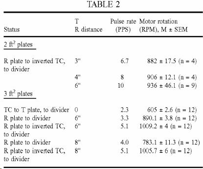
As shown in Table 2 above, the results of the experiment show that there is no loss of energy picked up at the R plate (Fig.10) when compared to the most favourable situation involving the plate 30 (Fig.9) interposed between the chirally connected coils. This observation is however not always the case. For best results one should employ iron, gold or silver plates placed parallel to the horizon, with the T plate underneath the R plate. In fact, if one employs instead aluminium plates and suspends these vertically, one can consistently register a loss of output at the divider when changing the divider input from the T to the R plates.
If however the plate R is connected in turn to a second identical coil, also wired in reverse, and this second coil in turn serves as input to the full-wave divider (Fig.11), then a most curious occurrence takes place - the power output increases considerably (see Table 2), as if the divider circuit had undergone an energy injection not present at the source. Note that the circuits are in fact resonant, but the energy injection contributing nearly 60-66% (for both plate areas in the previous experiment) of the input that we refer to, is not caused by inductive resonance, since the effect of resonance can be ascribed to the set-up described in Fig.9. The distance between the plates, as well as their orientation with respect to the local horizon system of the observer also appear to matter, best results being achieved at optimal distances (e.g. for 2 square feet plates the best gap, at 43% RH and room temperature, was at least 6 inches).
We tested the possibility that environmental heat produced by operation of the coil might be the source of the injected energy, the plate of the second system acting possibly as collector for the heat present in the gap. As it turned out, experiments showed repeatedly that in the gap between the T and R plates there was no significant thermal radiation propagating between one and the other. The more illustrative experiments are those in which we identified where the sensible thermal energy appears, and which involved coupling two cavities: the Transmitter-Receiver gap between plates T and R, and a Faraday cage enclosure 34 (see Fig.12). The first cavity appears to be much like that of a capacitor: the two identical parallel plates are surrounded by a thick dielectric insulator 32, and a thermometer T2 is inserted half-way through it. A thermometer T1 is also fixed to the T plate, to measure it’s temperature. The second cavity is a simple insulated metal cage with a thermometer T3 inserted 2 cm into its top. Some 2-4 cm above the top of the cage there is placed a fourth thermometer T4, inside an insulated cylinder.
If the Tesla
Coil is a source of thermal energy (e.g. IR radiation, microwaves, etc.) we
would expect the T plate to be the
hottest element from which, by radiation, thermal energy would reach the middle
of the first cavity making the next thermometer T2 second hottest, and that the third thermometer T3 inside the second cavity, even if it
might initially be slightly warmer than the other two, would, over time, become
comparatively cooler than either one of the other two thermometers, despite the
fact that the rising heat would still be seen to warm it up over time. One would expect a similar outcome for the
fourth thermometer T4, above the
cage. As shown by Fig.13, where only the temperature differences (![]() T0 - TC0) between the
experimental thermometers and the control thermometer reading the air
temperature TC0 of the laboratory are shown, the surface of the T plate warms up by 0.10C. at 3
minutes after initiation of the run (closed squares), whereas in the space of
the T/R gap a diminutive warming, by 0.050C., is registered after 10 minutes
(open circles). Conversely, the
temperature inside the cage, at the top (shaded circles) rises by 0.10C. also by the
third minute, and the temperature above the cage itself (shaded squares) rises
by a much greater difference of 0.350C., which remains stable after the
eighth minute.
T0 - TC0) between the
experimental thermometers and the control thermometer reading the air
temperature TC0 of the laboratory are shown, the surface of the T plate warms up by 0.10C. at 3
minutes after initiation of the run (closed squares), whereas in the space of
the T/R gap a diminutive warming, by 0.050C., is registered after 10 minutes
(open circles). Conversely, the
temperature inside the cage, at the top (shaded circles) rises by 0.10C. also by the
third minute, and the temperature above the cage itself (shaded squares) rises
by a much greater difference of 0.350C., which remains stable after the
eighth minute.
These results show that it is not sensible heat that radiates from the T plate. Instead, some other form of radiation traverses these cavities to generate sensible heat at their metallic boundaries, such that more heat is generated above the R plate (inside the cage) and again above the third plate, i.e. above the top of the cage, than is generated in the T/R gap, i.e. near the T plate. This clearly shows that the Tesla coil is not a significant source of thermal radiation, and that sensible heat can be detected inside and on top of the Faraday cage only as a further transformation of the radiant energy transmitted across the T/R cavity.
The same experiment also illustrates that, whatever is the nature of the additional environmental energy being injected at the surface of R plate (as shown by Table 2 results above), it is most likely not thermal radiation, at least not energy in the form of sensible heat. And whatever is the nature of this ambient radiant energy being mobilised by the electric radiant energy transmitted from the T plate, it can produce significant heat inside an enclosure adjacent to plate R.
Since we also
know experimentally, that this observation of an ambient energy injection at
the R plate or R cage depends upon relative humidity, being most easily observable
when the latter is low (<50% Relative Humidity), and being virtually
impossible to observe when air is saturated with water vapour, we can infer
that water vapour is a good absorber of the electric mass-free radiant energy
emitted from the T plate. This strongly
suggests that this absorption process is tantamount to increasing the potential
intrinsic energy ![]() of the water vapour molecules adjacent to the T plate. In the absence of significant quantities of
water vapour, when the atmosphere is dry, one may speculate that this
absorption process is replaced by what one presumes is a parallel process
involving the various gaseous molecules of air.
However, either because the air molecules involve molecular species that
readily give off this potential energy, as one might speculate is the case with
molecular oxygen, hydrogen and nitrogen, or because the air molecules absorb
far less "latent" energy (as appears to be the case with inert
gases), and therefore there is more of it in the molecularly unbound state (as
we explicitly propose as a possibility) and thus available for absorption by
the appropriately tuned receiver, the increased
of the water vapour molecules adjacent to the T plate. In the absence of significant quantities of
water vapour, when the atmosphere is dry, one may speculate that this
absorption process is replaced by what one presumes is a parallel process
involving the various gaseous molecules of air.
However, either because the air molecules involve molecular species that
readily give off this potential energy, as one might speculate is the case with
molecular oxygen, hydrogen and nitrogen, or because the air molecules absorb
far less "latent" energy (as appears to be the case with inert
gases), and therefore there is more of it in the molecularly unbound state (as
we explicitly propose as a possibility) and thus available for absorption by
the appropriately tuned receiver, the increased ![]() of air molecules conferred by the absorption
of the mass-free electric radiation in the T/R gap is transferred to the R conductor together with the latent
energy which those molecules already possessed before entering that gap. Hence the energy injection and its dependency
upon the partial pressure of water vapour, which absconds instead with this
"latent" energy and succeeds in withholding it from transmission to
the R plate.
of air molecules conferred by the absorption
of the mass-free electric radiation in the T/R gap is transferred to the R conductor together with the latent
energy which those molecules already possessed before entering that gap. Hence the energy injection and its dependency
upon the partial pressure of water vapour, which absconds instead with this
"latent" energy and succeeds in withholding it from transmission to
the R plate.
If the T/R gap can mobilise ambient energy which is neither electromagnetic nor thermal in nature, but which "latent" energy becomes injected into the divider circuit in electric form, the heat (i.e. sensible thermal energy) produced inside and on top of the cage, can also be mobilised electrically as input into the divider circuit. The obvious place to look for the positioning of the cool junction which could convert sensible heat into electrokinetic energy of mass-bound charges is at the top of the cage, where it is warmest (See top curve of Fig.13 in shaded squares). This is clearly observed from the results shown in Table 3 below, where the initial temperature difference between the top of the box and the T plate surface was 0.50C., and the top of the box temperature rose by 0.20C. after 2.5 minutes when the divider was connected at the junction, versus 0.350C. when it was not (and the transmitter coil was on).
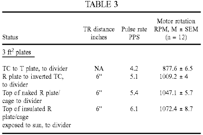
For the run performed with the naked R cage, the temperature directly above the top of the cage was 24.30C., at the outset, versus the control room temperature of 23.90C. For the run performed with the insulated R cage exposed directly to the sun at midday, on a cool and clear August day, the temperature directly above the top of the cage was 330C., versus the control air temperature of 18.40C. The temperature of the cool junction at the top of the cage was 31.90C. while the run was performed.
It is apparent from the data of Table 3, how a second injection of energy has occurred in the apparatus. If, within the T/R gap, the energy injected appears to be on the order of absorption of "latent heat", at the top of the cage cavity, at the cool junction, the injection is one of radiant "sensible" heat. Moreover, this secondary energy addition could be further enhanced by placing strong insulation around the whole apparatus or the cage itself, and further so, by exposing the whole apparatus to solar radiation.
We next turned our attention to the T/R gap cavity with the intention of determining whether atmospheric conditions or vacua yield the same or different results. We could not, of course, test the same large area plates as have been employed for the studies undertaken at atmospheric pressures. For the present purpose we employed instead large area electrodes (ca 0.2 ft2) made of high grade stainless steel or even aluminium. Preliminary results showed that these T/R gap tubes, when coupled to the divider circuit, yielded faster pulse rates in the secondary circuit when evacuated than at atmospheric pressure. The strength of the corona discharge also intensified, as it eventually became replaced by a normal glow discharge. For purposes of improved spatial capture of (1) the electric mass-free energy radiated from the T electrode and (2) the non-radiant latent thermal energy mobilised by it to be collected electrically at the R plate, an axial cylindrical T electrode was inserted inside a larger concentric cylinder or between two common plates of large surface area (e.g. >100 cm2) functioning as the R electrode(s), in a dielectric container suitable for evacuation (glass, polycarbonate), at a typical distance of at least 3 cm between electrodes, and the entire device was tested at different pressures.
The secondary circuit connected downstream from the full-wave divider was as shown in Fig.14 (employing an autogenous pulsed abnormal glow discharge, or PAGD, converter circuit), with the PAGD reactor 36 set at 10 Torr (in light of the high-voltage input, which varied between 1,500V and 3,200V) and gave the results presented in Table 4 below. We should remark also that these pulses charged the charge pack CP through the coupling capacitors 38, bridge rectifier 40 and reservoir capacitors 42, and blocking diodes 44, as expected from the prior art represented by our patents related to PAGD devices.
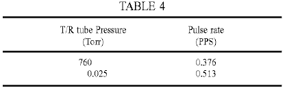
The effect of the vacuum in the T/R gap tube seems to be dual. By transforming the corona discharge into a normal glow discharge, it increases the local production of photons (probably associated to the formation and discharge of metastable states in the plasma), and at the same time, increases the pulse rate in the output circuit and thus, in all probability, the energy injected in the T/R gap cavity. But this did not yet permit us to confirm whether or not it is "latent heat" energy of the plasma molecules which is being tapped at the receiver plate, even if it be plausible in principle that plasmas may effect more efficient transfer of "latent heat" to tuned receivers than atmospheric gases.
The vacuum dependency of the pulse rate of the PAGD reactor employed as example in the secondary circuit downstream from the divider is also rather well marked, with the fastest pulse rates being registered at 1 Torr for the sample run shown in Table 5 below.
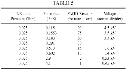
It is worth noting here that the illustrated polarity of the wiring of the PAGD reactor tube, as shown in Fig.14, is best for purposes of sustaining regular auto-electronic emission at high voltage. The reverse configuration, with the centre electrode negative and the plates positive favours instead heating of the cathode and a lapse into a normal glow discharge.
We tested a similar arrangement to that shown in Fig.14 above, but with a PAGD motor circuit (see our U.S. Pat. No. 5,416,391). A split-phase motor 44 replaces the rectifier and charge pack, and the PAGD reactor is operated at the same pressure of 15 Torr, as shown in Fig.15. The T/R gap tube tested had a longer plate distance (2''), with one plate now functioning as Transmitter and the other as Receiver. Note also the different wiring of the PAGD reactor. The results, as shown below in Table 6, present pulse per second (PPS) and motor revolutions per minute (RPM) curve trends that appear to be analogous and parallel to the well known Paschen curves for breakdown voltage in vacuum - such that the T/R gap performs better either in the atmospheric corona discharge mode, or in the high vacuum normal glow discharge (NGD) mode, than in the low breakdown voltage range of the curve where the discharge forms a narrow channel and takes on the appearance of an "aurora" transitional region discharge (TRD).
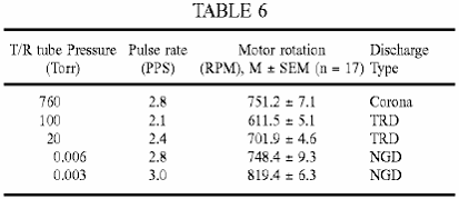
These results suggest that plasmas with high lateral dispersion, i.e. formed over large electrode areas (e.g. corona and NGD plasmas) and thus devoid of pinch, are more likely to mobilise electrically, the intrinsic potential energy of the molecular charges than pinch plasmas appear to be able to do (e.g. TRD plasmas). Apparently also, the greater the vacuum drawn from the T/R gap cavity, the more efficient does the transfer of this intrinsic potential energy become, i.e. the mass-bound latent heat, to the electrokinetic energy of the charges circulating in the receiver circuit. At about 0.06 Torr, this transfer in vacuo is comparable to that observed under atmospheric conditions and thus for a much greater density of molecules.
We investigated whether it Is possible to tap the latent heat energy of water molecules. It is possible that in the vapour phase they can effectively hold on to their latent energy - but could they give off some of it once closely packed in liquid phase? To test this hypothesis we immersed the T/R gap in a glass water tank. The motor employed for these tests was a high-speed 2-phase drag-cup motor (see Fig.18 and associated description), wired in split-phase with two identical phase windings capacitatively balanced, and the galvanised iron plates each had an area of one square foot. The results are shown in Table 7 below, and clearly indicate that it is possible to tap - within the T/R cavity - the `latent heat` of water in the liquid phase. As observed, immersion of the T/R cavity in water increased the motor output speed 22% (12,117 / 9,888) x 100). This corresponds to a 50% increase in power output, from 18W at 9,888 rpm to 27W at 12,117 rpm:
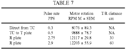
Thus the use of ion-containing water or other ion-containing aqueous liquid in the cavity promotes long distance propagation and a greater injection of latent and thermal energies in the receiver circuit. Such a result is not achieved if the cavity is filled with deionised water.
The preceding results lead therefore to the design of a presently preferred apparatus, based on these findings, for the conversion of mass-free electric energy, "latent heat" energy and "sensible" heat energy into conventional electric energy, as shown in Fig.16, which integrates all of the separate findings and improvements. The winding 6 of the Tesla coil at the bottom is driven in the usual manner employing a vibrator stage 2 to pulse the primary coil 4. The outer pole of the secondary 6 is then connected to a circular metal plate T which is one end of an evacuated cylindrical cavity, connected to a vacuum pump or sealed at a desired pressure, or which forms a still containing water or other aqueous solution or liquid. This cavity constitutes the transmitter/receiver gap, and is therefore bounded by a dielectric envelope and wall structure 32, with the circular receiver plate R as its top surface. In turn this plate R serves as the base of a conical Faraday cage 34, preferably air-tight and at atmospheric pressure, but which could also be subject to evacuation, which conical structure carries at its apex provisions for a cold junction 45 and any possible enhancement of the same junction by surface application of different metallic conductors that may optimise the Peltier-Seebeck effect. The output from the cold junction where sensible thermal energy is added to the electrokinetic energy of charge carriers, is also the input to the distal end of the winding 6 of the chiral coil arrangement that sustains resonant capture of all three energy flows ((1) mass-free electric waves of a longitudinal nature, (2) true "latent heat" or the intrinsic (thermal) potential energy, and (3) the thermokinetic energy of molecules, (i.e. "sensible" heat) and, placed in series with the input of the full wave divider 8, 10, feeds the circuit output from the series capacitors 12, 14 grounded at their common tap. In the T/R gap, the transmitted electric longitudinal wave energy is captured along with any intrinsic potential energy shed by molecules caught in the field. Within the R element, expanded into an enclosure that guides "sensible" radiant heat, the latter is generated and then recaptured at the cold junction.
The apparatus consisting of the cylindrical T/R gap cavity and the contiguous conical cage is then preferably finished in gloss white and cylindrically enveloped within a matt black container 46 by effective thermal insulation 48, the latter terminating at the height of the bottom disc T. Apparatus (not shown) may be provided to move the plate T vertically to adjust the T/R gap.
Another alternative embodiment of the apparatus is shown in Fig.17. Here the circuit driving the apparatus is as we have set forth in our prior patents, which employs an autogenous pulsed abnormal glow discharge tube 50 in the configuration shown, supplied by a battery pack DP through blocking diodes 52 and an RC circuit formed by resistor 54 and capacitor 56 to drive the primary 2 of a first Tesla coil to obtain at the distal pole of the secondary 6 the energy to be injected to plate T in the form of a central electrode of a coaxial vacuum chamber (sealed or not), of which the cylindrical metallic envelope forms the receiver plate R, the latter being placed centrally inside the conical cage 34 and contiguous with its walls and base. The top and bottom of the coaxial chamber carries suitable insulating discs, preferably with O-ring type fittings. Again, the apparatus is enclosed in insulation within a cylindrical container 46, and the input into the capture circuit driven from the full wave divider is taken from the cold junction 45 at the apex of the air-tight cage. The output circuit is similar to that of Fig.15.
We have found however that even when the component values in the motor driver and motor circuits are carefully selected so that these circuits are co-resonant with the dampened wave (DW) component of the motor driver pulses, the motor power output falls well short of that which should theoretically be attainable. In an endeavour to meet this problem, we replaced the squirrel-cage type induction motor 44 by a drag cup motor of type KS 8624 from Western Electric in the expectation that the low-inertia non-magnetic rotor would allow better response to the Dampened Wave component. This motor is similar to one of the types used by Reich in his experiments. Although results were much improved they still fell short of expectations. Replacement of this motor by an inertially dampened motor of type KS 9303, also from Western Electric, provided much better results as discussed below.
Fundamentally, the difficulties we encountered stemmed from the inability of motor couplings to respond efficiently and smoothly, and at the same time, to the pulse and wave components of Dampened Wave impulses: that is, simultaneously to the high-intensity peak current pulses (the front end event), the DC-like component, and to the dampened wave trains these cause, i.e. the pulse tails (or back end event)-or AC-like component. This difficulty is present even when we just seek to run induction motors from the DW impulses of a Tesla coil, the very difficulty that led Tesla to abandon his project of driving a non-ferromagnetic disc rotor mounted on an iron core bar stator with dampened waves.
We believe that the key to the capture of the mass-free energy flux output in electric form by Tesla transmitters, including any injected latent or thermal energy that have undergone conversion into electrical energy is to employ the tuned, unipolar, Y-fed, PAGD-plasma pulser driven split-phase motor drive we have invented (U.S. Pat. No. 5,416,391) in conjunction with an inertially dampened AC servomotor-generator (see Fig.18): this has a motor shaft 64 which couples a drag-cup motor rotor 60, preferably of aluminium, silver, gold or molybdenum, directly to a drag-cup generator rotor 62 that drives a permanent magnet (PM) flywheel 66, freely rotatable in bearings 67, that provides inertial damping. The shaft 64, journalled by bearings 61 in the casing of the motor 44, provides a power output through optional gearing 68. The phase windings of the motor 44 are wound on a stator core 70 having concentric elements between which the rotor or cup 60 rotates. This structure makes it ideal for the capture of the DW impulses, whether sourced in the transmitter, amplified in the T/R cavity or sourced in the plasma pulser, all in synchrony. Effectively the motor couples the damping action of the drag-cup sleeve motor rotor, which action, as we have already found for the KS-8624 motors, is quite effective at absorbing the front-end DC-like event, with the inertial damping of the PM flywheel upon the drag-cup sleeve generator rotor, that in turn is quite efficient at absorbing the back-end AC-like wavetrain event.
The KS-9154 motor used by Reich was not an inertial dampened AC drag-cup servomotor-generator. Had Reich succeeded in overcoming the limitations of his 2-phase OR Motor solution, as we have now shown it is possible to do (by applying the Function Y circuit to the PAGD split-phase motor drive which we invented), his motor would have suffered the same limitations which we encountered with the KS 8624 motor.
Any motor, by itself, has an internal or inherent damping whereby the acceleration only vanishes when the rotor is running at constant speed. For motors which operate on the basis of the drag principle, where the asynchronous slip is actually constitutive of the motor action, by inducing eddy currents in the rotor, the inherent damping is always more pronounced than for other induction motors. The damping or braking torque is produced when a constant current flows through a rotating drag disc or cup.
Aside from this inherent braking, dampers can also be applied to servo motors to further stabilise their rotation. They absorb energy, and the power output and torque of the motor is thereby reduced. Optimal operation of servo motors requires both rapid response on the part of the rotor to changes in the variable or control phase, and a stable response that is free from oscillation, cogging and overshooting. The rapid response is assured by employing low inertia rotors, such as drag-cups or cast alloy squirrel-cages, and the overshooting and oscillation are reduced to a minimum by damping or a retarding torque that increases with increasing motor speed. Typically, in a viscous-dampened servomotor, the damper is a drag-cup generator mounted rigidly on the shaft of the motor rotor, and the generator drag-cup rotates against the stator field of a static permanent magnet field. The generator develops a retarding torque directly proportional to speed, and the energy absorbed by the damper is proportional to speed squared. The damping can be adjusted and, as it increases, the same amount of input power yields lower torque and motor speeds. Inertial-dampened servo motors differ from viscous dampened motors in that the permanent magnet stator of the drag-cup generator is now mounted in its own bearings, either in the motor shaft or on a separate aligned shaft, forming a high-inertia flywheel.
This means that, whereas the motor rotor always experiences a viscous damping in viscous-dampened servo motors, in inertial-dampened servo motors the drag cup motor rotor only experiences a viscous damping while accelerating the flywheel, with the damping torque always opposing any change in rotor speed. Once the flywheel rotates synchronously with the rotor, all damping ceases. Note that this viscous damping is carried out via the coupling of the drag-cup generator rotor, rigidly affixed to the motor rotor, to the PM flywheel, so that their relative motion generates the viscous torque proportional to the relative velocity. Use of drag-cup sleeve rotors in inertially dampened servo motors was largely supplanted by squirrel-cage rotors once the latter became produced as cast alloy rotors. Since inertially dampened motors can be used in open and closed-loop servo applications, and present better stability - even in the presence of non-linearities - and higher velocity characteristics than other induction motors do (Diamond, A (1965) "Inertially dampened servo motors, performance analysis", Electro-Technology, 7:28-32.), they have been employed in antenna tracking systems, stable inertial-guidance platforms, analogue to digital converters, tachometers and torque tables.
The typical operation of an inertially dampened servomotor is as follows: with the reference phase fully excited, the motor rotor -fixedly linked to the generator rotor, as well as the flywheel - remain immobile; once power is applied to the control phase, the motor rotor immediately responds but the flywheel remains at rest. However, as the drag-cup generator 62 is forced to move through the permanent magnetic field of the flywheel, it creates a drag torque that slows down the attached motor rotor proportionally to the acceleration that it imparts to the flywheel that it now sets into motion, thus creating the viscous damper. As the flywheel accelerates, the relative speed of the motor with respect to the flywheel, as well as the damping torque, decrease until both motor and flywheel rotate synchronously and no damping torque is exercised - at which point the drag on the motor cup exerted by the generator cup is negligible.
The KS-9303 motor is an inertial dampened servomotor but is differentiated with respect to other inertially dampened motors, in that (1) it employs a drag-cup sleeve motor rotor made of aluminium, very much like that of the KS-8624, but with slightly altered dimensions and with a shaft extension for the drag-cup copper generator rotor, and (2) the moving flywheel structure was journalled on a separate, fixed shaft, as already described with reference to Fig.18. Now, in principle, even application of minimal damping decreases motor efficiency, resulting in diminished torque and speed. Whether the inertial-dampened motor has a drag-cup rotor, a sleeve rotor or a squirrel-cage rotor, the damping increases the rotor slip. Laithwaite considers drag-cup motors as being "dynamically inferior to their cage counterparts" (Laithwaite, E R (1957) "Induction machines for special purposes", London, England, p. 323). If we now add a viscous damping and retarding torque, we should not be able to get much more than a 55% efficiency in the best of conditions. On the other hand, the inertial damping arrangement described will only abstract or supply energy when the motor rotor is accelerating or decelerating relative to the flywheel.
These drag-cup motors, whether inertially dampened or not, develop a constant torque at constant rpm for a given supply frequency and a suitable phase shift capacitance. For each frequency the motors respond to, there is an optimum resonant split-phase capacitance, but other values nearby are still suited for operation, and for each value of capacitance, there is an optimum frequency to which the motors respond. For example the KS-8624 motor responds best at 450 Hz when a 1 microfarad capacitance is employed, responds best at 250 Hz when a capacitance of 10 microfarads is employed, and responds best at 60 Hz, when a capacitance of 100 microfarads is employed. As the capacitance increases, the resonant CW frequency of the motor is displaced to lower values. If we fix the capacitance at a value (e.g. 10 microfarads) suitable for testing the frequency response at a fixed voltage of 12 VAC, the observed result for both the KS-8624 and KS-9303 motors show a response distribution of the motor rotary velocity that has an identical peak at 250 Hz for both motors, with the response decreasing to zero smoothly on both sides of the peak.
These results indicate that, when wired as a split-phase motor, the motor rotary velocity varies not as a function of voltage or current, but as a function of frequency when the phase-splitting capacitance is fixed within a suitable range, there being an optimum frequency mode for each value of suitable capacitance, with lower values of capacitance favouring higher frequency modes. For a given frequency and capacitance, the motor rotary velocity remains essentially constant and independent from voltage and current input, and thus at a plateau. Torque, in the same circuit arrangement, follows exactly the same pattern as rotary velocity, as a function of input frequency at a fixed potential. Torque is linearly proportional to rpm in these motors when they are split-phase wired, and rpm linearly proportional to CW frequency, which makes them ideal for experimentation and determination of power output computations. Moreover, since these are drag machines, the slip itself determines the rotor currents and these are susceptible to tuning such that their retardation and relative position in the field can find resonant modes for varying CW frequency and capacitance.
In the circuit of Fig.17 when using the KS 9303 motor, the inertial damping of the flywheel coupling retards the motor rotor currents sufficiently to allow them to build up torque, with the entire motor assembly serving as the preferred sink for all of the energy, mass-free and mass-bound, captured by the receiving coil circuit with a drawing action established by the motor on the circuit, and providing satisfactory absorption by an inertial damper of the combined, synchronised, dampened wave impulses, those occurring at a low frequency as a result of the firing of the PAGD reactor, and those occurring at a higher superimposed frequency -sourced in the transmitter circuit and picked-up by the receiver plate and coil. The action of each DW impulse train itself generates two different events: the DC-like auto-electronic-like discontinuity which sets the motor in motion and initiates the rotor currents, and the AC-like dampened wavetrain which supports the consistency of those rotors. The concentration of current required to kick-start the motor is provided by the DW impulses of the PAGD reactor, whereas, once the motor is in motion, and particularly, once it is stabilised by the flywheel, the cumulative action of the higher frequency DW impulses makes itself felt by accelerating the rotor to an optimum rotary velocity.
For the next series of tests we employed the basic circuit diagram of the improved motor shown in Fig.19. The transmission station is the typical Tesla transmitter with a line-fed, 60 Hz vibrator stage. At the line input to the first stage, we place a calibrated AC wattmeter (Weston Model 432), and a Beckman 330B rms ammeter in series with the hot lead, we set the vibrator stage for 41 clicks, consuming between 28.5W and 35W, depending upon circumstances yet to be described. This consumption was confirmed by driving the coil from an inverter powered by a 12 volt battery. The inverter consumes 2.16 watts, and is 90% efficient. The total consumption from the battery was 42 watts (12V at 3.5A); once the 2.16 watts is deducted and the efficiency taken into account, we obtain the same 36W (vibrator stage at max., i.e. 47 clicks, in this experiment). The T/R gap is adjusted to 3'', and 2 square foot plates are used. Transmitter and receiver coils are tuned, and so are the plate capacitances, to 250 kHz, also the capacitances of the Function Y circuit connected at the output of the receiving coil.
The rectified voltage and current generated by the transmitter secondary and by the transmitter plate was ascertained with a coil-tuned wave-divider (Function Y) circuit by loading it with different resistive values. The results constitute a measure of the mass-bound electrical power output directly from the transmitter apparatus. The same method was employed to ascertain the voltage, current and power of the mass-bound charges circulating in the receiving plate and coil circuit. The results are shown in Table 8 below:
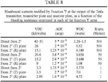
The results indicate that the highest mass-bound power assembled by the secondary transmitter circuit does not exceed 7 watts - and this is directly output from the secondary 26 when the load is 50 Megohm, or from the transmitter plate when the load is 1 Megohm. The mass-bound electric power emulated by the receiving circuit (plate, coil and Function Y without the plasma pulser circuitry) never exceeds the mass-bound electric power outputted directly by the transmitter, and peaks when the resistive load value (1 Megohm) approaches the pre-breakdown resistance range of the vacuum tube, at 4.72W. These findings then indicate that when the transmitter circuit is consuming a maximum of 35W, a typical output from the secondary of the transmitter is 7W, and at 3'' of distance within the proximal field of the latter, the pick-up by a tuned receiver will be of the order of 5W of mass-bound current duplicated within the receiving coil. The loss in the first stage is therefore on the order of sevenfold.
Continuing with the description of the circuit of Fig.19, a 128 cm2 plate area, 6 cm gap PAGD reactor is used, connected as described in our prior art to a high-vacuum rotary pump (Correa, P & Correa, A (1995) "Energy conversion system", U.S. Pat. No. 5,449,989). Pressure readings were obtained with a thermocouple gauge during the operational runs. The KS-9303 motors to be tested are then connected to the PAGD reactor in the usual capacitatively-coupled, inverter fashion described in our prior art (Correa, P & Correa, A (1995) "Electromechanical transduction of plasma pulses", U.S. Pat. No 5,416.391). Their rpm is detected by a stroboscopic tachometer and fed to a Mac Performa 6400 running a motor algorithm program calculating the power output. Motor measurements were made at five minutes into each run for the unloaded motors, and at ten minutes for the inertially dampened motors.
All experiments were carried out in the same work session. The experimental determination of the continuous rotary power output as a function of the reactor pulse rate confirmed that the improved circuit develops maximum rotary capture of the mass-free energy in the receiver circuit at the lowest rates of pulsation, just as we have previously found for the conversion system of U.S. Pat. No. 5,449,989. Furthermore, the data showed that even motors of type KS-8624 are able to output power mechanically in excess of the mass-bound power output by the transmitter (7W) or captured by the receiver (5 to a max. of 7W), once the PAGD rate decreases to 1.5 PPS. Such an anomaly can only be explained by the system having become able to begin capturing the mass-free energy flux in the receiver circuit that we know already is output by the transmitter circuit. But this excess mechanical power is still less than the power input into the transmitter, and clearly so. It represents a power gain with respect to the secondary, but a loss with respect to the primary. The full breadth of the capture of the mass-free electric energy flux circulating in the receiver circuit is not seen until the motors are resonantly loaded because they are inertially dampened.
The KS-9303 motors, once inertially dampened, and thus loaded, are able to recover enough power from the mass-free energy field to develop a mechanical power, not just greatly in excess of the mass-bound power of the secondary, but also greatly in excess of the mass-bound power input to the vibrator stage and the primary, at 28 to 35W. Once the pulse rate approaches the same 1.5 PPS marker, mechanical power in excess of the mass-bound electric power input to the primary becomes evident, peaking at nearly three times that input. In fact, the highest output recorded was also obtained with the lowest input to the transmitter circuit, the highest exact coefficient observed in this experiment being 100.8W / 28W = 3.6. Furthermore, with respect to the secondary mass-bound output, the same mechanical rotary output represents a much greater overunity coefficient of performance, on the order of 14.4 times greater. This is at least partly the result of the receiver and motor capture of the mass-free electric energy output by the transmitter, and may be partly the result of mass-free energy engrafted by the PAGD regime in the PAGD reactor.
Reviewing the mechanical power output results as a function of increasing vacuum in the PAGD reactor and at different output power levels, any motor performance below the 5-7W limit of the traditional mass-bound output power of the secondary represents an output mechanical power loss with respect to both the mass-bound secondary output and the mass-bound primary input. All the results for pressures down to 0.03 Torr fall into this category, and thus represent a very inefficient coupling to the PAGD regime. Any motor performance between 7W and 28-35W represent a loss with respect to the electrical power input to the transmitter system, but a net gain of power with respect to the mass-bound secondary power output. None of the non-inertially dampened motors tested were able to perform outside of this area, under the test conditions. With more efficient primary to secondary couplings in the transmitter station, however, one could advantageously employ these motors alone to extract some of the mass-free power of the secondary or to operate them in enclosed vessels without conventional external electrical connections.
To reach satisfactory levels of recovery of mass-free energy, one must dampen the superimposed DW impulses. Hence, all results showing outputs in excess of 35W were obtained using the inertially dampened KS-9303 motors, and represent a net overunity power gain over both the power input to the primary and the mass-bound power output by the secondary, or the mass-bound power emulated by the receiver circuitry. This happens when the PAGD pulse rate falls to 2 PPS, with the rotary power output steeply increasing as the rate falls to 1 PPS.
One of the interesting features of the motor circuitry we have proposed is that it can operate with pulsed plasmas in both the TRD and the AGD regions, the least efficient response occurring in the NGD region near the Paschen minimum. One might think that the voltage depression would allow increased current intensity supplied to the motors, but in fact that is not observed, with the flashing of the NGD yielding erratic oscillations and low values of current. In keeping with the notion that the TRD plasma is mainly composed of lagging positive ions, whereas the PAGD plasma is mostly an electron plasma, the observed direction of rotation of the motors is opposite in the TRD region to that of the AGD region. The NGD region therefore marks the depression where the velocity vectors change direction. In the second or PAGD region, motor operation is very quiet, unlike what is observed in the TRD region.
Part and parcel of the tuning of the circuit components is the selection of the optimum capacitances employed to couple the PAGD reactor to the motor circuit and split the phase to feed the auxiliary winding of the motor. We have experimented with capacitances ranging from 0.5 to 100 microfarads, and found that best results (for the specific circuit in question - including the characteristics of the transmission), were such that the optimum value of the PAGD coupling capacitance lay near 4 microfarads, and the phase splitting capacitance, near 1 to 4 microfarads, depending upon weather conditions. In good weather days lower capacitance values can be used, while in bad weather days higher capacitances are needed. For ease of comparison in demonstrating the need to tune the circuit by employing optimum capacitances in those two couplings (reactor to motor, and motor phase coupling), we employed the same capacitances in both circuit locations.
A comparison of tests using 1 and 4 microfarad values shows the difference caused by changing those capacitances from their optimum value: across all discharge regions of the pressure range that was examined, the four motors tested, operated with greater motor speeds when the capacitances are set to 4 microfarads rather than to 1 microfarad. The less efficient performance obtained with 1 microfarad capacitance fits the inverse correlation of pulse power with increasing pulse frequency, such as we have found for the PAGD regime. This is made evident by a comparison of rpm versus pulse rate for the two capacitance values being considered. They demonstrate the higher pulse rates observed with the lower capacitance, that correlate with the lower motor speeds, and result in lower efficiency of the motor response. The results equally indicate that low capacitance values increase the pulse rate, but if this increase is out of tune with the rest of the circuit values, it results in power waste because it imposes a rate that is not optimum.
We have also determined experimentally that the efficiency of the system is affected by external weather conditions, higher efficiencies being noted on a fine bright day than under poor weather conditions even though the apparatus is not exposed to such conditions. This may reflect a diminution under poor weather conditions of latent mass-free energy that can be taken up by the system.
The observed high efficiency of circuits including inertially dampened motors indicates that the phenomenon does not reduce to a mere optimum capture of, DC-like pulses produced by the reactor in what is essentially an AC motor circuit. Effectively, the pulsed plasma discharge deploys a front-end, DC-like pulse, or discontinuity, but this is followed by an AC-like dampened wave of a characteristic frequency (having a half-cycle periodicity identical to that of the front-end pulse) to which the motor circuit also responds. Moreover, the mass-free electric radiation from the transmitter circuit itself induces, in the receiver antenna, coil and circuit, and in the reactor discharge itself, the train of finer dampened wave impulses responsible, after conversion through the wave-divider, for the mass-bound rectified current which is employed to charge the plasma reactor to begin with. Serving as trigger of the plasma discharges in the reactor are the DW impulses circulating in the receiver circuit, such that the two different lines of DW impulses, in the receiver circuit (for example 120 PPS for the pulses and 154 kHz for the waves) and from the reactor, are synchronised by interpolated coincidences, since their pulse and wave frequencies are different. Ideally, these two superimposed DW frequencies are harmonics or made identical. The receiver stage involves capture of the mass-free electric energy received from the transmitter, duplication of the mass-bound current in the receiver coil, and injection of latent and sensible thermal energy in the T/R gap cavity which augments the emulated mass-bound current.
The mass-bound current is employed to charge the wave-divider capacitance bridge and therefore the reactor. In turn, the plasma pulses from the reactor are superimposed with the DW impulses from the receiving coil, and together they are coupled to the split-phase motor drive. Hence the first receiver stage employs the totality of the energy captured in the T/R gap cavity - mass-free electric energy transmitted by the T plate, latent and sensible thermal energy injected at the surface of the R plate - and produces in the receiving coil a mass-bound current comparable to that assembled in the transmitter coil by the action of the primary. The mass-bound current is stored in the wave-divider bridge and used to drive the plasma reactor in the PAGD region. Subsequently, the autogenous disruptive discharge that employs a substantial electron plasma generates both a concentrated, intense flux of mass-bound charges in the output circuit, and a mass-free oscillation of its own. The dampened motor is therefore fed directly with (1) the intense mass-bound current output from the reactor; (2) the pulse and wave components of the mass-free electric energy captured by the receiver plate and coil (and matched by conduction through the earth), and which are gated through the wave-divider and the reactor for the duration of the PAGD channel; and (3) any mass-free latent energy taken up from the vacuum by the PAGD event. Once the motor is set into motion, and is resonantly loaded with an inertial damper, we believe that it will also respond to the much weaker DW impulses captured by the receiver, since these impulses encompass both a DC-like front end - further enhanced by analytic separation through the wave-divider - and a dampened wave at 154 kHz.
Essentially, the DW impulses that are ultimately sourced in the transmitter - and received unipolarly through the T/R gap - have sufficient DC-like potential (plus all the other requisite physical characteristics, such as frequency) to contribute directly to the motor response, once the motor has gained substantial speed (for they lack the current to set it into motion, one of the contributions from the plasma pulser). This is the case, provided that the motor itself is suited for absorption of both DC-like pulses and AC-like dampened waves, which is precisely the case with motors of the type shown in Fig.18 since the inertia of the flywheel is overcome through homopolar absorption of the dampened oscillations simultaneously in the motor drag-cup rotor and in the generator drag-cup rotor.
We also tested these inertially dampened motors in the traditional DC power supply-driven PAGD circuit we have taught in our previous patents, that is, circuits with an overt HV DC power source, and thus in the absence of any Function Y circuit or transmitter circuit. Here then, only the DW impulses generated by the PAGD reactor can account for the motor response. The tube employed (A31) had an area of 256 cm2, and a gap distance of 4 cm. Coupling capacitances employed were 4 microfarads for the inverter coupling, and 1 microfarad for the split phase motor coupling. The DC power supply delivered up to 1 ampere of current between 150 and 1,000 VDC, and the ballast resistor was adjusted to 215 ohms. Having determined the basic physical characteristics of the reactor's behaviour in the circuit under consideration, we conducted our experiment in the PAGD region. We chose a pressure of 0.6 Torr, just off from the Paschen minimum, as we intended to benefit from the lower sustaining voltage which it affords.
The experiment basically consisted of increasing the sustaining voltage at this fixed pressure in the PAGD regime, and measuring the diverse physical parameters of the circuit and motor response in order to ultimately ascertain the difference between the input electric DC power and the output mechanical rotary power. We first looked at how the motor rpm response varied as a function of the sustaining voltage (Vs): the results illustrate the importance of starting close to the Paschen minimum in the pressure scale, since the KS-9303 motors reach plateau response (at 17,000 rpm) when the reactor output voltage nears 450V. Any further increase in potential is simply wasted. Likewise, the same happened when we measured motor speed as a function of increasing peak DC current, plateau response being reached at 0.1 ADC. Again, any further increase in current is wasted. Essentially then, the optimal power input to the reactor when the output of the latter is coupled to the motor, lies around 45 watts. This is a typical expenditure in driving a PAGD reactor. As for pulse rate we once again find a motor response that is frequency proportional in the low frequency range, between 10 and 40 PPS (all pulse rates now refer solely to PAGDs per sec), but once rates of >40 PPS are reached, the response of the motor also reaches a plateau.
The observed increment in speed from 40 to 60 PPS translates only into an increase of 1,000 RPM, from 16,000 to 17,000 RPM. So, we can place the optimal PAGD rate at ca 40 PPS. The DC electric power input to drive the PAGD reactor was next compared to the rotary mechanical power output by the inertially loaded motor, driven in turn by the reactor. This comparison was first carried out with respect to the PAGD rates. The motor response far exceeds the conventional input power, indicating that the whole system can be tuned to resonance such that optimal power capture inside the reactor takes place, the critical limit rate lying at around 60 PPS, when the motor response is firmly within the pulse response plateau. At this juncture, the break-even efficiency for the measured rates of energy flux over time reach 700% (overunity coefficient of 7), in keeping with the observations and the values we have made in the PAGD conversion system. In the proportional part of the curve, before the plateau is reached, even greater rates of break-even efficiency - up to >1,000% were registered.
These results constitute the first time we have been able to confirm the presence of output energy in excess of break-even over conventional mass-bound energy input in the PAGD inverter system, and the results are comparable to what we have observed and previously reported for the PAGD converter system. At pulse rates greater than 60 PPS a greater input power results in decreased efficiency, also translated into a noticeable heating of the reactor and motor. And this is all the more remarkable as experiments we have conducted with inductive tuning of PAGD reactors, or employing PAGD reactors as replacements for the primaries of Tesla coil assemblies, and still, more recently, with the PAGD inverter circuit driving motors, have all shown that it is possible to operate these reactors with minimal mirroring and heating, preserving essentially the cold-cathode conditions and yet focusing the plasma column so that deposition on the insulator is negligible. It appears that above a certain threshold of optimal efficiency, surplus input energy is just dissipated thermally by both the reactor and the motors.
It should be understood that the above described embodiments are merely exemplary of our invention, and are, with the exception of the embodiments of Figs. 16 to 19 designed primarily to verify aspects of the basis of the invention. It should also be understood that in each of these embodiments, the transmitter portion may be omitted if an external or natural source of Tesla waves is available, provided that the receiver is tuned to the mass-free radiation mode of the source. For example if solar radiation is available in which the mass-free component has not interacted with the earth's atmosphere (as in space applications), the receiver is tuned to the voltage wave of the mass-free radiation sourced in the sun, e.g. by using a Tesla coil in the receiver constructed to have an appropriate voltage wave close to the 51.1 kV characteristic of such radiation.
US Patent 4,936,961 June 26, 1990 Inventor:
METHOD FOR
THE PRODUCTION OF A FUEL GAS
Please note
that this is a re-worded excerpt from this patent. It describes one of the methods which Stan
used to split water into hydrogen and oxygen using very low levels of input
power.
OBJECTS OF
THE INVENTION
It is an object of the invention to provide a fuel cell and a process in which molecules of water are broken down into hydrogen and oxygen gases, and other formerly dissolved within the water is produced. As used herein the term "fuel cell" refers to a single unit of the invention comprising a water capacitor cell, as hereinafter explained, that produces the fuel gas in accordance with the method of the invention.
BRIEF
DESCRIPTION OF THE DRAWINGS:
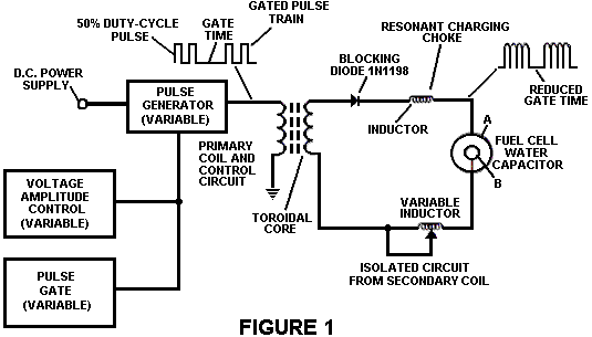
Fig.1 Illustrates a circuit
useful in the process.
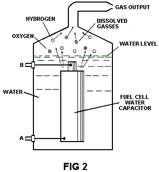
Fig.2 Shows a perspective of a "water capacitor" element used in the fuel cell circuit.
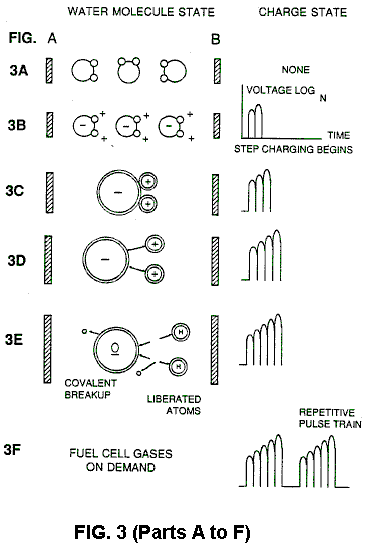
Figs. 3A through 3F are illustrations depicting the theoretical bases for the phenomena encountered during operation of the invention herein.
DESCRIPTION
OF THE PREFERRED EMBODIEMENT
In brief, the invention is a method of obtaining the release of a gas mixture including hydrogen on oxygen and other dissolved gases formerly entrapped in water, from water consisting of:
(a) Providing a capacitor, in which the water is included as a dielectric liquid between capacitor plates, in a resonant charging choke circuit that includes an inductance in series with the capacitor;
(b) Subjecting the capacitor to a pulsating, unipolar electric voltage field in which the polarity does not pass beyond an arbitrary ground, whereby the water molecules within the capacitor are subjected to a charge of the same polarity and the water molecules are distended by their subjection to electrical polar forces;
(c) Further subjecting in said capacitor to said pulsating electric field to achieve a pulse frequency such that the pulsating electric field induces a resonance within the water molecule;
(d) Continuing the application of the pulsating frequency to the capacitor cell after resonance occurs so that the energy level within the molecule is increased in cascading incremental steps in proportion to the number of pulses;
(e) Maintaining the charge of said capacitor during the application of the pulsing field, whereby the co-valent electrical bonding of the hydrogen and oxygen atoms within said molecules is destabilised such that the force of the electrical field applied, as the force is effective within the molecule, exceeds the bonding force of the molecule, and hydrogen and oxygen atoms are liberated from the molecule as elemental gases; and
(f) Collecting said hydrogen and oxygen gases, and any other gases that were formerly dissolved within the water, and discharging the collected gases as a fuel gas mixture.
The process follows the sequence of steps shown in the following Table 1 in which water molecules are subjected to increasing electrical forces. In an ambient state, randomly oriented water molecules are aligned with respect to a molecule polar orientation.
They are next, themselves polarised and "elongated" by the application of an electrical potential to the extent that covalent bonding of the water molecule is so weakened that the atoms dissociate and the molecule breaks down into hydrogen and oxygen elemental components.
Engineering design parameters based on known theoretical principles of electrical circuits determine the incremental levels of electrical and wave energy input required to produce resonance in the system whereby the fuel gas comprised of a mixture of hydrogen, oxygen, and other gases such as air were formerly dissolved within the water, is produced.
TABLE
1
----------------------------------------------------------------------------------------------------------------------------
Process Steps:
The sequence of the relative state of the water molecule and/or hydrogen/oxygen/other atoms:
----------------------------------------------------------------------------------------------------------------------------
A. (ambient state)
random
B. Alignment of polar fields
C. Polarisation of molecule
D. Molecular elongation
E. Atom liberation by breakdown of covalent bond
F. Release of gases
----------------------------------------------------------------------------------------------------------------------------
In the
process, the point of optimum gas release is reached at a circuit resonance.
Water in the fuel cell is subjected to a pulsating, polar electric field
produced by the electrical circuit whereby the water molecules are distended by
reason of their subjection to electrical polar forces of the capacitor plates.
The polar pulsating frequency applied is such that the pulsating electric field
induces a resonance in the molecule. A cascade effect occurs and the overall
energy level of specific water molecules is increased in cascading, incremental
steps. The hydrogen and oxygen atomic gases, and other gas components formerly
entrapped as dissolved gases in water, are released when the resonant energy
exceeds the covalent bonding force of the water molecule. A preferred
construction material for the capacitor plates is T304-grade stainless steel
which is
non-chemical reactive with water,
hydrogen, or oxygen. An electrically conductive material which is inert in the
fluid environment is a desirable material of construction for the electrical
field plates of the "water capacitor" employed in the circuit.
Once triggered, the gas output is controllable by the attenuation of operational parameters. Thus, once the frequency of resonance is identified, by varying the applied pulse voltage to the water fuel cell assembly, gas output is varied. By varying the pulse shape and/or amplitude or pulse train sequence of the initial pulsing wave source, final gas output is varied. Attenuation of the voltage field frequency in the form of OFF and ON pulses likewise affects output.
The overall apparatus thus includes an electrical circuit in which a water capacitor having a known dielectric property is an element. The fuel gases are obtained from the water by the disassociation of the water molecule. The water molecules are split into component atomic elements (hydrogen and oxygen gases) by a voltage stimulation process called the electrical polarisation process which also releases dissolved gases entrapped in the water.
From the outline of physical phenomena associated with the process described in Table 1, the theoretical basis of the invention considers the respective states of molecules and gases and ions derived from liquid water. Before voltage stimulation, water molecules are randomly dispersed throughout water in a container. When a unipolar voltage pulse train such as shown in Figs.3B through 3F is applied to positive and negative capacitor plates, an increasing voltage potential is induced in the molecules in a linear, step like charging effect. The electrical field of the particles within a volume of water including the electrical field plates increases from a low energy state to a high energy state successively is a step manner following each pulse-train as illustrated figuratively in the depictions of Figs.3A through 3F. The increasing voltage potential is always positive in direct relationship to negative ground potential during each pulse. The voltage polarity on the plates which create the voltage fields remains constant although the voltage charge increases. Positive and negative voltage "zones" are thus formed simultaneously in the electrical field of the capacitor plates.
In the first stage of the process described in Table 1, because the water molecule naturally exhibits opposite electrical fields in a relatively polar configuration (the two hydrogen atoms are positively electrically charged relative to the negative electrically charged oxygen atom), the voltage pulse causes initially randomly oriented water molecules in the liquid state to spin and orient themselves with reference to positive and negative poles of the voltage fields applied. The positive electrically charged hydrogen atoms of said water molecule are attracted to a negative voltage field; while, at the same time, the negative electrically charged oxygen atoms of the same water molecule are attracted to a positive voltage field. Even a slight potential difference applied to inert, conductive plates of a containment chamber which forms a capacitor will initiate polar atomic orientation within the water molecule based on polarity differences.
When the potential difference applied causes the orientated water molecules to align themselves between the conductive plates, pulsing causes the voltage field intensity to be increased in accordance with Fig.3B. As further molecule alignment occurs, molecular movement is hindered. Because the positively charged hydrogen atoms of said aligned molecules are attracted in a direction opposite to the negatively charged oxygen atoms, a polar charge alignment or distribution occurs within the molecules between said voltage zones, as shown in Fig.3B. And as the energy level of the atoms subjected to resonant pulsing increases, the stationary water molecules become elongated as shown in Fig.3C and Fig.3D. Electrically charged nuclei and electrons are attracted toward opposite electrically charged equilibrium of the water molecule.
As the water molecule is further exposed to an increasing potential difference resulting from the step charging of the capacitor, the electrical force of attraction of the atoms within the molecule to the capacitor plates of the chamber also increase in strength. As a result, the covalent bonding between which form the molecule is weakened --- and ultimately terminated. The negatively charged electron is attracted toward the positively charged hydrogen atoms, while at the same time, the negatively charged oxygen atoms repel electrons.
In a more specific explanation of the "sub-atomic" action the occurs in the water fuel cell, it is known that natural water is a liquid which has a dielectric constant of 78.54 at 20 degrees C. and 1 atmosphere pressure. [Handbook of Chemistry & Physics, 68th ed., CRC Press(Boca Raton, Florida (1987-88)), Section E-50. H20(water)].
When a volume of water is isolated and electrically conductive plates, that are chemically inert in water and are separated by a distance, are immersed in water, a capacitor is formed, having a capacitance determined by the surface area of the plates, the distance of their separation and the dielectric constant of water.
When water molecules are exposed to voltage at a restricted current, water takes on an electrical charge. By the laws of electrical attraction, molecules align according to positive and negative polarity fields of the molecule and the alignment field. The plates of the capacitor constitute such as alignment field when a voltage is applied.
When a charge is applied to a capacitor, the electrical charge of the capacitor equals the applied voltage charge; in a water capacitor, the dielectric property of water resists the flow of amps in the circuit, and the water molecule itself, because it has polarity fields formed by the relationship of hydrogen and oxygen in the covalent bond, and intrinsic dielectric property, becomes part of the electrical circuit, analogous to a "microcapacitor" within the capacitor defined by the plates.
In the Example
of a fuel cell circuit of Fig.1, a
water capacitor is included. The step-up coil is formed on a conventional
toroidal core formed of a compressed ferromagnetic powered material that will
not itself become permanently magnetised, such as the trademarked
"Ferramic 06# "Permag" powder as described in Siemens Ferrites
Catalogue, CG-2000-002-121, (
In the circuit of Fig.1, the diode is a 1N1198 diode which acts as a blocking diode and an electric switch that allows voltage flow in one direction only. Thus, the capacitor is never subjected to a pulse of reverse polarity.
The primary coil of the toroid is subject to a 50% duty cycle pulse. The toroidal pulsing coil provides a voltage step-up from the pulse generator in excess of five times, although the relative amount of step-up is determined by preselected criteria for a particular application. As the stepped-up pulse enters first inductor (formed from 100 turns of 24 gauge wire 1 inch in diameter), an electromagnetic field is formed around the inductor, voltage is switched off when the pulse ends, and the field collapses and produces another pulse of the same polarity i.e., another positive pulse is formed where the 50% duty cycle was terminated. Thus, a double pulse frequency is produced; however, in pulse train of unipolar pulses, there is a brief time when pulses are not present.
By being so subjected to electrical pulses in the circuit of Fig.1, water confined in the volume that includes the capacitor plates takes on an electrical charge that is increased by a step charging phenomenon occurring in the water capacitor. Voltage continually increases (to about 1000 volts and more) and the water molecules starts to elongate.
The pulse train is then switched off; the voltage across the water capacitor drops to the amount of the charge that the water molecules have taken on, i.e., voltage is maintained across the charged capacitor. The pulse train is the reapplied.
Because a voltage potential applied to a capacitor can perform work, the higher the voltage the higher the voltage potential, the more work is performed by a given capacitor. In an optimum capacitor that is wholly non-conductive, zero (0) current flow will occur across the capacitor. Thus, in view of an idealised capacitor circuit, the object of the water capacitor circuit is to prevent electron flow through the circuit, i.e. such as occurs by electron flow or leakage through a resistive element that produces heat. Electrical leakage in the water will occur, however, because of some residual conductivity and impurities or ions that may be otherwise present in the water. Thus, the water capacitor is preferably chemically inert. An electrolyte is not added to the water.
In the isolated water bath, the water molecule takes on charge, and the charge increases. The object of the process is to switch off the covalent bonding of the water molecule and interrupt the subatomic force, i.e. the electrical force or electromagnetic force, that binds the hydrogen and oxygen atoms to form a molecule so that the hydrogen and oxygen separate.
Because an electron will only occupy a certain electron shell (shells are well known) the voltage applied to the capacitor affects the electrical forces inherent in the covalent bond. As a result of the charge applied by the plates, the applied force becomes greater than the force of the covalent bonds between the atom of the water molecule; and the water molecule becomes elongated. When this happens, the time share ratio of the electron shells is modified.
In the process, electrons are extracted from the water bath; electrons are not consumed nor are electrons introduced into the water bath by the circuit as electrons are conventionally introduced in as electrolysis process. There may nevertheless occur a leakage current through the water. Those hydrogen atoms missing electrons become neutralised; atoms are liberated from the water. The charged atoms and electrons are attracted to the opposite polarity voltage zones created between the capacitor plates. The electrons formerly shared by atoms in the water covalent bond are reallocated such that neutral elemental gases are liberated.
In the
process, the electrical resonance may be reached at all levels of voltage
potential. The overall circuit is characterised as a "resonant charging
choke" circuit which is an inductor in series with a capacitor that
produces a resonant circuit. [SAMS Modern Dictionary of Electronics, Rudolf
Garff, copyright 1984, Howard W. Sams & Co. (
As noted initially, the capacitance depends on the dielectric properties of the water and the size and separation of the conductive elements forming the water capacitor.
EXAMPLE 1
In an example of the circuit of Fig.1 (in which other circuit element specifications are provided above), two concentric cylinders 4 inches long formed the water capacitor of the fuel cell in the volume of water. The outside cylinder was 0.75 inch in outside diameter; the inner cylinder was 0.5 inch in outside diameter. Spacing from the outside of the inner cylinder to the inner surface of the outside cylinder was 0.0625 inch. Resonance in the circuit was achieved at a 26 volt applied pulse to the primary coil of the toroid at 0 KHz (suspected mis-typing for 10KHz), and the water molecules disassociated into elemental hydrogen and oxygen and the gas released from the fuel cell comprised a mixture of hydrogen, oxygen from the water molecule, and gases formerly dissolved in the water such as the atmospheric gases or oxygen, nitrogen, and argon.
In achieving resonance in any circuit, as the pulse frequency is adjusted, the flow of amps is minimised and the voltage is maximised to a peak. Calculation of the resonance frequency of an overall circuit is determined by known means; different cavities have a different frequency of resonance dependant on parameters of the water dielectric, plate size, configuration and distance, circuit inductors, and the like. Control of the production of fuel gas is determined by variation of the period of time between a train of pulses, pulse amplitude and capacitor plate size and configuration, with corresponding value adjustments to other circuit components.
The wiper arm on the second conductor tunes the circuit and accommodates to contaminants in water so that the charge is always applied to the capacitor. The voltage applied determines the rate of breakdown of the molecule into its atomic components. As water in the cell is consumed, it is replaced by any appropriate means or control system.
Variations of the process and apparatus may be evident to those skilled in the art.
US Patent 4,389,981 28th June 1983 Inventor:
HYDROGEN GAS
INJECTOR SYSTEM FOR INTERNAL COMBUSTION ENGINES
Please note
that this is a re-worded excerpt from this patent. It describes one method for using hydrogen
and oxygen gases to fuel a standard vehicle engine.
ABSTRACT
System and apparatus for the controlled intermixing of a volatile hydrogen gas with oxygen and other non-combustible gasses in a combustion system. In a preferred arrangement the source of volatile gas is a hydrogen source, and the non-combustible gasses are the exhaust gasses of the combustion system in a closed loop arrangement. Specific structure for the controlled mixing of the gasses, the fuel flow control, and safety are disclosed.
CROSS
REFERENCES AND BACKGROUND
There is
disclosed in my co-pending
In my co-pending patent application filed May 5, 1981, U.S. Serial No. 262,744 now abandoned for Hydrogen-Airdation Processor, non-volatile and non-combustible gasses are controlled in a mixing stage with a volatile gas. The hydrogen airdation processor system utilises a rotational mechanical gas displacement system to transfer, meter, mix, and pressurise the various gasses. In the gas transformation process, ambient air is passed through an open flame gas-burner system to eliminate gasses and other substances present. After that, the non-combustible gas-mixture is cooled, filtered to remove impurities, and mechanically mixed with a pre-determined amount of hydrogen gas. This results in a new synthetic gas.
This synthetic gas-formation stage also measures the volume and determines the proper gas-mixing ratio for establishing the desired burn-rate of hydrogen gas. The rotational mechanical gas displacement system in that process determines the volume of synthetic gas to be produced.
The above-noted hydrogen airdation processor, of my co-pending application, is a multi-stage system suited to special applications. Whereas the hydrogen generator system of my other mentioned co-pending application does disclose a very simple and unique hydrogen generator.
In my co-pending patent application Serial No. 315,945, filed Oct. 18, 1981 there is disclosed a combustion system incorporating a mechanical drive system. In one instance, this is designed to drive a piston in an automotive device. There is shown a hydrogen generator for developing hydrogen gas, and perhaps other non-volatile gasses such as oxygen and nitrogen. The hydrogen gas with the attendant non-volatile gasses is fed via a line to a controlled air intake system. The combined hydrogen, non-volatile gasses, and the air, after inter-mixing, are fed to a combustion chamber where they are ignited. The exhaust gasses of the combustion chamber are returned in a closed loop arrangement to the mixing chamber to be used again as the non-combustible gas component. Particular applications and structural embodiments of the system are disclosed.
SUMMARY OF
THE INVENTION
The system of the present invention in its most preferred embodiment is for a combustion system utilising hydrogen gas; particularly to drive the pistons in an car engine. The system utilises a hydrogen generator for developing hydrogen gas. The hydrogen gas and other non-volatile gasses are then fed, along with oxygen, to a mixing chamber. The mixture is controlled in such a way as to lower the temperature of the combustion to bring it in line with that of the currently existing commercial fuels. The hydrogen gas feed line to the combustion chamber includes a fine linear control gas flow valve. An air intake is the source of oxygen and it also includes a variable valve. The exhaust gasses from the combustion chamber are utilised in a controlled manner as the non-combustible gasses.
The hydrogen generator is improved by the inclusion of a holding tank which provides a source of start-up fuel. Also, the hydrogen gas generator includes a pressure-controlled safety switch on the combustion chamber which disconnects the input power if the gas pressure rises above the required level. The simplified structure includes a series of one-way valves, safety valves, and quenching apparatus. The result is an apparatus which comprises the complete assembly for converting a standard car engine from petrol (or other fuels) to use a hydrogen/gas mixture.
OBJECTS
It is accordingly a principal object of the present invention to provide a combustion system of gasses combined from a source of hydrogen and non-combustible gasses.
Another object of the invention is to provide such a combustion system that intermixes the hydrogen and non-combustible gasses in a controlled manner and thereby control the combustion temperature.
A further object of the invention is to provide such a combustion system that controls the fuel flow to the combustion chamber in s system and apparatus particularly adapted to hydrogen gas.
Still other objects and features of the present invention will become apparent from the following detailed description when taken in conjunction with the drawings in which:
BRIEF
DESCRIPTION OF THE DRAWINGS
Fig.1 is a mechanical schematic illustration partly in block form of the present invention in its most preferred embodiment.
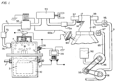
Fig.2 is a block schematic illustration of the preferred embodiment of the hydrogen injector system shown in Fig.1.
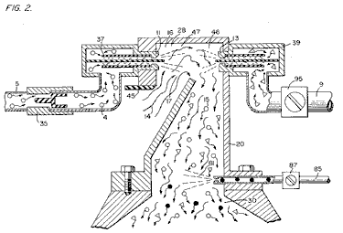
Fig.3 is the fine linear fuel flow control shown in Fig.1.
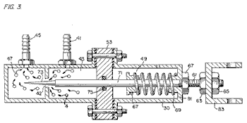
Fig.4 is cross-sectional illustration of the complete fuel injector system in an car utilising the concepts of the present invention.
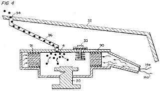
Fig.5 is a schematic drawing in a top view of the fuel injector system utilised in the preferred embodiment.
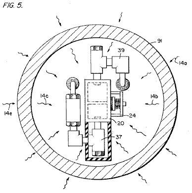
Fig.6 is a cross-sectional side view of the fuel injector system in the present invention.
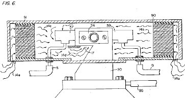
Fig.7 is a side view of the fuel mixing chamber.
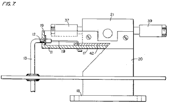
Fig.8 is a top view of the air intake valve to fuel mixing chamber.
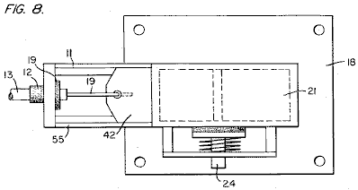
Fig.9 is a comparison of the burning velocity of hydrogen with respect to other fuels.
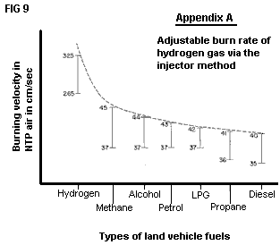
DETAILED DESCRIPTION OF INVENTION TAKEN
WITH DRAWINGS:
Referring to Fig.1 the complete overall gas mixing and fuel flow system is illustrated together for utilisation in a combustion engine, particularly an engine in a car. With specific reference to Fig.1, the hydrogen source 10 is the hydrogen generator disclosed and described in my co-pending application, supra. The container 10 is an enclosure for a water bath 2. Immersed in the water 2 is an array of plates 3 as further described in my co-pending application, supra. Applied to plates 3 is a source of direct current potential via electrical inlet 27. The upper portion 7 of the container 10 is a hydrogen storage area maintaining a predetermined amount of pressure. In this way, there will be an immediate flow of hydrogen gas at start-up.
To replenish the expended water, the generator provides a continuous water source 1. Thereafter, the generator is operable as described in the aforesaid patent application. The safety valve 28 is designed to rupture should there be an excessive build-up of gas. Switch 26 is a gas-pressure switch included to maintain a predetermined gas pressure level about a regulated low-volume.
The generated hydrogen gas 4 is fed from the one-way check valve 16 via pipe 5 to a gas-mixing chamber 20, where the hydrogen gas is mixed with non-combustible gasses via pipe 9 from a source described later.
If the one-way valve 75 failed, there could be a return spark which could ignite the hydrogen gas 4 in the storage area 7 of the hydrogen generator 10. To prevent this, the quenching assembly 76 has been included to prevent just such an ignition.
With particular reference to Fig.2, the hydrogen gas (via pipe 5) and non-combustible gasses (via pipe 9), are fed to a carburettor (air-mixture) system 20 also having an air intake 14 for ambient air.
The hydrogen gas 4 is fed via line 5 through nozzle 11 in a spray 16 in to the trap area 46 of the mixing chamber 20. Nozzle 11 has an opening smaller than the plate openings in the quenching assembly 37, thereby preventing flash-back in the event of sparking. The non-volatile gasses are injected into mixing chamber 20 trap area 47 in a jet spray 17 via nozzle 13. Quenching assembly 39 is operable much in the same manner as quenching assembly 37.
In the preferred arrangement, the ambient air is the source of oxygen necessary for the combustion of the hydrogen gas. Further, as disclosed in the aforesaid co-pending application, the non-volatile gasses are in fact, the exhaust gasses passed back via a closed loop system. It is to be understood that the oxygen and/or the non-combustible gasses might also be provided from an independent source.
With continued reference to Fig.2 the gas trap area 47 is a predetermined size. As hydrogen is lighter than air, the hydrogen will rise and become trapped in area 47. Area 47 is large enough to contain enough hydrogen gas to allow instant ignition upon the subsequent start-up of the combustion engine.
It will be noted that the hydrogen gas is injected in the uppermost region of the trap area 47. Hydrogen rises at a much greater rate than oxygen or the non-combustible gasses; perhaps three times or greater. Therefore, if the hydrogen gas entered the trap area 47 (mixing area) at its lowermost region the hydrogen gas would rise so rapidly that the air could not mix with the oxygen. With the trap area 47 shown in Fig.2, the hydrogen is forced downwards into the air intake 15. That is, the hydrogen gas is forced downwards into the upwardly forced air and this causes adequate mixing of the gasses.
The ratio of the ambient air (oxygen) 14 and the non-combustible gas via line 9 is a controlled ratio which is tailored to the particular engine. Once the proper combustion rate has been determined by the adjustment of valve 95 (for varying the amount of the non-combustible gas) and the adjustment of valve 45 (for varying the amount of the ambient air), the ratio is maintained thereafter.
In a system where the non-combustible gasses are the exhaust gasses of the engine itself, passed back through a closed loop-arrangement, and where the air intake is controlled by the engine, the flow velocity and hence the air/non-combustible mixture, is maintained by the acceleration of the engine.
The mixture of air with non-combustible gasses becomes the carrier for the hydrogen gas. That is, the hydrogen gas is mixed with the air/non-combustible gas mixture. By varying the amount of hydrogen gas added to the air/non-combustible mixture, the engine speed is controlled.
Reference is made to Fig.3 which shows in a side view cross-section, the fine linear fuel flow control 53. The hydrogen gas 4 enters chamber 43 via gas inlet 41. The hydrogen gas passes from chamber 43 to chamber 47 via port or opening 42. The amount of gas passing form chamber 43 to chamber 47 is dictated by the setting of the port opening 42.
The port opening is controlled by inserting the linearly tapered pin 73 into it. The blunt end of pin 73 is fixed to rod 71. Rod 71 is passed, (via supporting O-ring 75), through opening 81 in housing 30, to the manual adjustment mechanism 83.
Spring 49 retains the rod 71 in a fixed position relative to pin 73 and opening 42. When mechanism 83 is operated, pin 73 moves back from the opening 42. As pin 73 is tapered, this backward movement increases the free area of opening 42, thereby increasing the amount of gas passing from chamber 43 to chamber 47.
The stops 67 and 69 maintain spring 49 in its stable position. The nuts 63 and 67 on threaded rod 61 are used to set the minimum open area of opening 42 by the correct positioning of pin 73. This minimum opening setting, controls the idle speed of the engine, so pin 73 is locked in its correct position by nuts 63 and 67. This adjustment controls the minimum rate of gas flow from chamber 43 to chamber 47 which will allow continuous operation of the combustion engine.
Referring now to Fig.8 which illustrates the air adjustment control for manipulating the amount of air passing into the mixing chamber 20. The closure 21 mounted on plate 18 has an opening 17 on end 11. A plate-control 42 is mounted so as to slide over opening 17. The position of this plate, relative to opening 17, is controlled by the position of the control rod 19 which passes through grommet 12 to control line 13. Release valve 24 is designed to rupture should any malfunction occur which causes the combustion of the gasses in mixing chamber 20.
With reference now to Fig.4, if hydrogen gas 4 were to accumulate in mixing chamber 20 and reach an excessive pressure, the escape tube 36 which is connected to port 34 (located on the car bonnet 32), permits the excess hydrogen gas to escape safely to the atmosphere. In the event of a malfunction which causes the combustion of the gasses in mixing chamber 20, the pressure relief valve 33 will rupture, expelling the hydrogen gas without combustion.
In the constructed arrangement of Fig.1, there is illustrated a gas control system which may be fitted to an existing car’s internal combustion engine without changing or modifying the car's design parameters or characteristics. The flow of the volatile hydrogen gas is, of course, critical; therefore, there is incorporated in line 5 a gas-flow valve 53, and this is used to adjust the hydrogen flow. This gas-flow valve is shown in detail in Fig.3.
The intake air 14 may be in a carburettor arrangement with an intake adjustment 55 which adjusts the plate 42 opening. This is shown more fully in Fig.8. To maintain constant pressure in hydrogen gas storage 7 in the on-off operation of the engine, the gas flow control valve is responsive to the electrical shut-off control 33. The constant pressure permits an abundant supply of gas on start-up and during certain periods of running time in re-supply.
The switch 33 is in turn responsive to the vacuum control switch 60. During running of the engine vacuum will be built up which in turn leaves switch 33 open by contact with vacuum switch 60 through lead 60a. When the engine is not running the vacuum will decrease to zero and through switch 60 will cause electrical switch 33 to shut off cutting off the flow of hydrogen gas to the control valve 53.
As low-voltage direct current is applied to safety valve 28, solenoid 29 is activated. The solenoid applies a control voltage to the hydrogen generator exciter 3 via terminal 27 through pressure switch 26. As the electrical power activates solenoid 29, hydrogen gas is caused to pass through flow adjustment valve 16 and then outlet pipe 5 for utilisation. The pressure differential hydrogen gas output to gas mixing chamber 20 is for example 30 lbs. to 15 lbs. Once hydrogen generator 10 reaches an optimum gas pressure level, pressure switch 26 shuts off the electrical power to the hydrogen excitors. If the chamber pressure exceeds a predetermined level, the safety release valve 28 is activated disconnecting the electrical current and thereby shutting down the entire system for safety inspection.
With particular reference now to Fig.6 which illustrates the fuel injector system in a side cross-sectional view and to Fig.5 the top view. The structural apparatus incorporated in the preferred embodiment comprises housing 90 which has air intakes 14a and 14e. The air passes through filter 91 around the components 14b and 14c and then to intake 14d of the mixing chamber 20. The hydrogen enters via line 5 via quenching plates 37 and into the mixing chamber 20. The non-volatile gasses pass via line 9 to the quenching plates 39 and into the mixing chamber 20.
Fig.7 illustrates the mechanical arrangement of the components which make up the overall structure of mixing chamber 20 (shown independently in the other figures).
Returning to Fig.1 there is illustrated the non-volatile gas line 9 passing through mixture pump 91 by engine pulley 93. Valve 95 controls the rate of flow. Also driven by pulley 93 is pump 96 having line 85 connected to an oil reservoir 92 and valve 87 and finally to mixing chamber 20. As a practical matter, such as in a non-oil lubricated engine, lubricating fluid such as oil 81 is sprayed in the chamber 20, via oil supply line 85 for lubrication.
There have been several publications in the past year or so, delving into the properties of Hydrogen gas, its potential use, generating systems, and safety. One such publication is "Selected Properties of Hydrogen" (Engineering Design Data) issued February 1981 by the National Bureau of Standards.
These publications are primarily concerned with the elaborate and costly processes for generating hydrogen. Equally so, they are concerned with the very limited use of hydrogen gas because of its extremely high burning velocities. This in turn reflects the danger in the practical use of hydrogen.
With reference to the graph of the Appendix A, it is seen that the burning velocities of alcohol, propane, methane, petrol, Liquid Petroleum Gas, and diesel oil are in the range of minimum 35 to maximum 45. Further, the graph illustrates that the burning velocity of hydrogen gas is in the range of 265 minimum to 325 maximum. In simple terms, the burning velocity of hydrogen is of the order of 7.5 times the burning velocity of ordinary commercial fuels.
Because of the unusually high burning velocity of hydrogen gas, it has been ruled out as a substitute fuel, by these prior investigators. Further, even if an engine could be designed to accommodate such high burning velocities, the danger of explosion would eliminate any thoughts of commercial use.
The present invention, as above described, has resolved the above-noted criteria for the use of hydrogen gas in a standard commercial engine. Primarily, the cost in the generation of hydrogen gas, as noted in the aforementioned co-pending patent applications, is minimal. Water with no chemicals or metals is used. Also, as noted in the aforementioned co-pending patent applications, the reduction in the hydrogen gas burn velocity has been achieved. These co-pending applications not only teach the reduction in velocity, but teach the control of the velocity of the hydrogen gas.
In the preferred embodiment, practical apparatus adapting the hydrogen generator to a combustion engine is described. The apparatus linearly controls the hydrogen gas flow to a mixing chamber mixing with a controlled amount of non-combustible gas oxygen, hence, the reduction in the hydrogen gas velocity. The reduction in the hydrogen gas velocity makes the use of hydrogen as safe as other fuels.
In more practical terms the ordinary internal combustion engine of any size or type of fuel, is retrofitted to be operable with only water as a fuel source. Hydrogen gas is generated from the water without the use of chemicals or metals and at a very low voltage. The burning velocity of the hydrogen gas has been reduced to that of conventional fuels. Finally, every component or step in the process has one or more safety valves or features thereby making the hydrogen gas system safer than that of conventional cars.
In the above description the terms ‘non-volatile’ and ‘non-combustible’ were used. It is to be understood they are intended to be the same; that is, simply, gas which will not burn.
Again, the term ‘storage’ has been used, primarily with respect to the hydrogen storage area 7. It is not intended that the term ‘storage’ be taken literally - in fact, it is not storage, but a temporary holding area. With respect to area 7, this area retains a sufficient amount of hydrogen for immediate start-up.
Other terms, features, apparatus, and the such have been described with reference to a preferred embodiment. It is to be understood modifications and alternatives can be had without departing from the spirit and scope of the invention.
US Patent 4,421,474 December 1983 Inventor:
HYDROGEN GAS
BURNER
Please note
that this is a re-worded excerpt from this patent. It describes how to burn the hydrogen and
oxygen gas mix produced by electrolysis of water. Normally, the flame produced is too hot for
practical use other than cutting metal or welding. This patent shows a method of reducing the
flame temperature to levels suitable for general use in boilers, stoves,
heaters, etc.
ABSTRACT
A hydrogen gas burner for the mixture of hydrogen gas with ambient air and non-combustible gasses. The mixture of gasses when ignited provides a flame of extremely high, but controlled intensity and temperature.
The structure comprises a housing and a hydrogen gas inlet directed to a combustion chamber positioned within the housing. Air intake ports are provided for adding ambient air to the combustion chamber for ignition of the hydrogen gas by an ignitor therein. At the other end of the housing there is positioned adjacent to the outlet of the burner (flame) a barrier/heating element. The heating element uniformly disperses the flame and in turn absorbs the heat. The opposite side to the flame, the heating element uniformly disperses the extremely hot air. A non-combustible gas trap adjacent to the heating element captures a small portion of the non-combustible gas (burned air). A return line from the trap returns the captured non-combustible gas in a controlled ratio to the burning chamber for mixture with the hydrogen gas and the ambient air.
CROSS
REFERENCE
The hydrogen/oxygen generator utilised in the present invention is that disclosed and claimed in my co-pending patent application, Serial. No.: 302,807, filed: Sept. 16, 1981, for: HYDROGEN GENERATOR SYSTEM. In that process for separating hydrogen and oxygen atoms from water having impurities, the water is passed between two plates of similar non-oxidising metal. No electrolyte is added to the water. The one plate has placed thereon a positive potential and the other a negative potential from a very low amperage direct-current power source. The sub-atomic action of the direct current voltage on the non-electrolytic water causes the hydrogen and oxygen atoms to be separated--and similarly other gasses entrapped in the water such as nitrogen. The contaminants in the water that are not released are forced to disassociate themselves and may be collected or utilised and disposed of in a known manner.
The direct current acts as a static force on the water molecules; whereas the non-regulated rippling direct current acts as a dynamic force. Pulsating the direct current further enhances the release of the hydrogen and oxygen atoms from the water molecules.
In my co-pending patent application, Serial. No. 262,744, filed: May 11, 1981, for: HYDROGEN AERATION PROCESSOR, there is disclosed and claimed the utilisation of the hydrogen/oxygen gas generator. In that system, the burn rate of the hydrogen gas is controlled by the controlled addition of non-combustible gasses to the mixture of hydrogen and oxygen gasses.
SUMMARY OF
INVENTION
The present invention is for a hydrogen gas burner and comprises a combustion chamber for the mixture of hydrogen gas, ambient air, and non-combustible gasses. The mixture of gasses is ignited and burns at a retarded velocity rate and temperature from that of hydrogen gas, but at a higher temperature rate than other gasses.
The extremely narrow hydrogen gas mixture flame of very high temperature is restricted from the utilisation means by a heat absorbing barrier. The flame strikes the barrier which in turn disperses the flame and absorbs the heat therefrom and thereafter radiates the heat as extremely hot air into the utilisation means.
Positioned on the opposite side of the heat radiator/barrier is a hot air trap. A small portion of the radiated heat is captured and returned to the combustion chamber as non-combustible gasses. Valve means in the return line regulates the return of the non-combustible gas in a controlled amount to control the mixture.
The present invention is principally intended for use with the hydrogen generator of my co-pending patent application, supra; but it is not to be so limited and may be utilised with any other source of hydrogen gas.
OBJECTS
It is accordingly a principal object of the present application to provide a hydrogen gas burner that has a temperature controlled flame and a heat radiator/barrier.
Another object of the present invention is to provide a hydrogen gas burner that is capable of utilising the heat from a confined high temperature flame.
Another object of the present invention is to provide a hydrogen gas burner that is retarded from that of hydrogen gas, but above that of other gasses.
Another object of the present invention is to provide a hydrogen gas burner that utilises the exhaust air as non-combustible gas for mixture with the hydrogen gas.
Another object of the present invention is to provide a hydrogen gas burner that is simple but rugged and most importantly safe for all intended purposes.
Other objects and features of the present invention will become apparent from the following detailed description when taken in conjunction with the drawings in which:
BRIEF DESCRIPTION OF THE DRAWINGS
Fig.1 is an overall cross-sectional
view of the present invention in its most preferred embodiment.
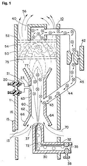
Fig.2 is a graphical illustration of
the burning of various standard fuels with that of hydrogen velocities.
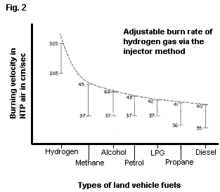
DETAILED
DESCRIPTION OF INVENTION
With particular reference Fig.1 there is illustrated in a schematic cross-section the principals of the present invention. The structure of the preferred embodiment comprises a housing 10, having an igniter 20 extending through the wall 11 thereof. A combustion chamber 60 positioned within the housing 10 has a first open end 62. A hydrogen gas 72 inlet 30 directs hydrogen gas via port 37 from a source 35 to the inlet 62 of the combustion chamber 68. Also directed to the same inlet 62, and assisted by flanges 64 and 66, is ambient air 70 entering through ports 13 in the housing 10.
Adjacent the opposite end of the combustion chamber 60 the gas mixture 75 is ignited by the ignitor 20 to produce flame 77. The velocity of the flame 77 causes it to strike and penetrate the barrier/radiator 50. The barrier 50 is of a material, such as metallic mesh or ceramic material, to disperse therein the flame and in turn become saturated with heat. The flame 77 is of a size sufficient to be dispersed throughout the barrier 50, but yet, not penetrate through the barrier 50.
Radiated from the surface 52 of the barrier 50 is superheated air 56 (gasses) to be passed on to a utilisation device. Adjacent to surface 52 of barrier/radiator 50 is a hot air trap 40 with closed loop line 45 returning non-combustible gas 44 to the combustion chamber 60. Control valve 42 is intermediate the line 45.
In operation of the preferred embodiment hydrogen gas, 72, emitted from the nozzle 37 is directed to the combustion chamber 60. The flanges 64 and 66 on the open end of housing 63 of the combustion chamber 60 enlarges the open end of 62. In the enlargement ambient air from the opening 13 in the housing 10 is also directed to the combustion chamber 60.
The ambient air and hydrogen traverses the opening 43 and further mixes with the non-combustible gas 44 from the closed loop line 45 with the hot air trap 40. The mixture of hydrogen gas 72, ambient air 70, and non-combustible gas 44, is ignited by the ignitor 20 having electrical electrodes 21 and 23. Upon ignition flame 77 ensues. The mixture is controlled with each of three gasses. That is, the line 32 from the hydrogen source 35 has a valve 38 therein for controlling the amount of hydrogen 72 emitted from the nozzle 37. The opening 13 has a plate adjustment 15 for controlling the amount of ambient air 60 directed to the combustion chamber 60, and the closed-loop line has valve 42, as aforesaid, for controlling the amount of non-combustible gasses in the mixture.
It can be appreciated that the temperature of the flame 77 and the velocity of the flame 77 is a function of the percentage of the various gasses in the mixture. In a practical embodiment, the flame 70 temperature and velocity was substantially retarded from that of a hydrogen flame per se; but yet, much greater than the temperature and velocity of the flame from the gasses utilised in a conventional heating system.
To maintain a sufficient pressure for combustion of the hydrogen gas mixture with a minimum of pressure (for safety) and to limit blow-out, the nozzle 37 opening 39 is extremely small. As a consequence, if the hydrogen gas were burned directly from the nozzle 37, the flame would be finite in diameter. Further, its velocity would be so great it is questionable whether a flame could be sustained. The mixing of ambient air and non-combustible gas does enlarge the flame size and reduce its velocity. However, to maintain a flame higher in temperature and velocity than the conventional gasses, the size and temperature of the flame is controlled by the mixture mentioned earlier.
Therefore, to utilise the flame 77 in a present day utilisation means, the flame is barred by the barrier 50. The barrier 50 is of a material that can absorb safely the intense flame 77 and thereafter radiate heat from its entire surface 52. The material 54 can be a ceramic, metallic mesh or other heat absorbing material known in the art. The radiated heat 56 is directed to the utilisation means.
As stated earlier, the mixture of gasses which are burned include non-combustible gasses. As indicated in the above-noted co-pending patent applications, an excellent source of non-combustible gasses is exhaust gasses. In this embodiment, the trap 50 entraps the hot air 74 and returns the same, through valve 42, to the combustion chamber 60 as non-combustible gas.
With reference to Fig.2 there is illustrated the burning velocity of various standard fuels. It can be seen the common type of fuel burns at a velocity substantially less than hydrogen gas. The ratio of hydrogen with non-combustible oxygen gasses is varied to obtain optimum burning velocity and temperature for the particular utilisation. Once this is attained, the ratio, under normal conditions, will not be altered. Other uses having different fuel burn temperature and velocity will be adjusted in ratio of hydrogen/oxygen to non-combustible gasses in the same manner as exemplified above.
Further, perhaps due to the hydrogen gas velocity, there will occur unburned gas at the flame 77 output. The barrier 50, because of its material makeup will retard the movement and trap the unburned hydrogen gas. As the superheated air 77 is dispersed within the material 54, the unburned hydrogen gas is ignited and burns therein. In this way the barrier 50 performs somewhat in the nature of an after-burner.
US Patent 5,149,407 22nd September 1992 Inventor:
PROCESS AND
APPARATUS FOR THE PRODUCTION OF FUEL GAS AND
THE ENHANCED RELEASE OF THERMAL ENERGY FROM SUCH GAS
Please note
that this is a re-worded excerpt from this patent. It describes in considerable detail, one of
Stan’s methods for splitting water into hydrogen and oxygen gasses and the
subsequent methods for using those gasses.
ABSTRACT
Water molecules are broken down into hydrogen and oxygen gas atoms in a capacitive cell by a polarisation and resonance process dependent on the dielectric properties of water and water molecules. The gas atoms are then ionised or otherwise energised and thermally combusted to release a degree of energy greater than that of combustion of the gas in air.
OBJECTS OF
THE INVENTION
A first object of the invention is to provide a fuel cell and a process in which molecules of water are broken down into hydrogen and oxygen gasses, and a fuel gas mixture comprised of hydrogen, oxygen and other gasses formerly dissolved in the water, is produced. A further object of the invention is to realise significant energy-yield from a fuel gas derived from water molecules. Molecules of water are broken down into hydrogen and oxygen gasses. Electrically charged hydrogen and oxygen ions of opposite electrical polarity are activated by electromagnetic wave energy and exposed to a high temperature thermal zone. Significant amounts of thermal energy with explosive force beyond the gas burning stage are released.
An explosive
thermal energy under a controlled state is produced. The process and apparatus provide a heat
energy source useful for power generation, aircraft rocket engines or space
stations.
BRIEF DESCRIPTION OF THE DRAWINGS
Figs.1A through 1F are illustrations depicting the theoretical bases for phenomena encountered during operation of the fuel gas production stage of the invention.
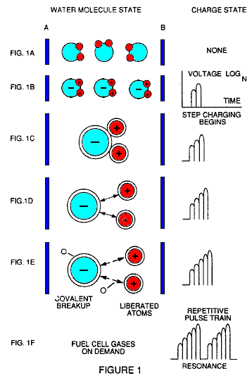
Fig.2 illustrates a circuit which is useful in the fuel gas generation process.
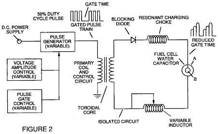
Fig.3 shows a perspective of a “water capacitor” element used in the fuel cell circuit.
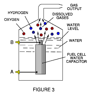
Fig.4 illustrates a staged arrangement of apparatus useful in the process, beginning with a water inlet and culminating in the production of thermal explosive energy.
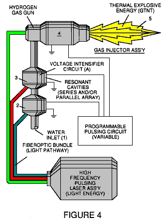
Fig.5A shows a cross-section of a circular gas resonant cavity used in the final stage assembly of Fig.4
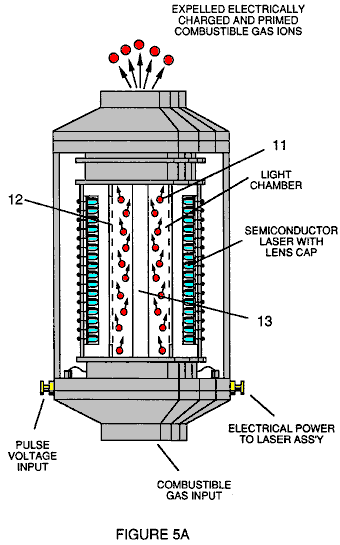
Fig.5B shows an alternative final stage injection system useful in the apparatus of Fig.4

Fig.5C shows an optical thermal lens assembly for use with either final stage of Fig.5A or Fig.5B.
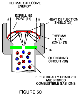
Figs.6A, 6B, 6C and 6D are illustrations depicting various theoretical bases for atomic phenomena expected to occur during operation of this invention.
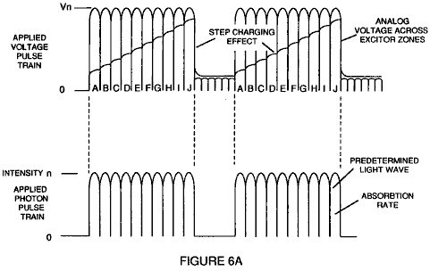
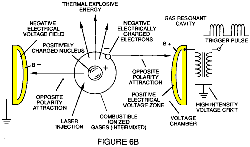
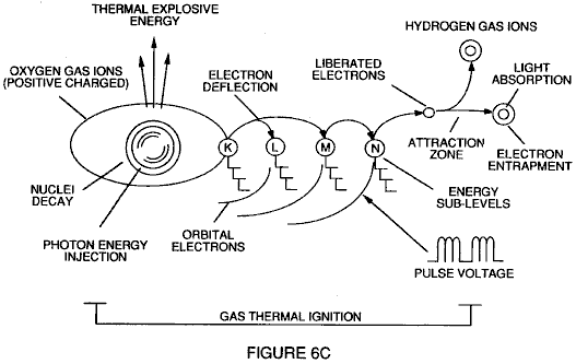
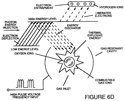
Fig.7 is an electrical schematic of the voltage source for the gas resonant cavity.
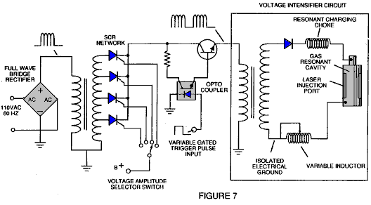
Figs.8A and 8B respectively, show (A) an electron extractor grid used in the injector assemblies of Fig.5A and Fig.5B, and (B) the electronic control circuit for the extractor grid.
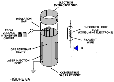
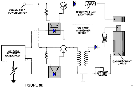
Fig.9 shows an alternative electrical circuit useful in providing a pulsating waveform to the apparatus.
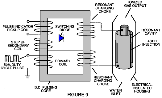
TABLE 1: PROCESS STEPS LEADING TO IGNITION
|
Relative
State of |
Stage |
|
Random (ambient state) alignment of polar fields, polarisation of molecules. Molecular elongation. Atom liberation by breakdown of covalent bond |
1st Stage: Water to Gas |
|
Release of gasses, Liquid to gas ionisation, Electrical charging effect, Particle Impact |
2nd Stage: Gas Ionisation |
|
Electromagnetic Wave, Laser or photon injection, Electron extraction, Atomic destabilisation |
3rd Stage: Priming |
|
Thermal Ignition |
Final Stage: Ignition |
DESCRIPTION OF THE PREFERRED EMBODIMENT
A fuel gas is produced by a hydrogen fracturing process which follows the sequence of steps shown in Table 1. Beginning with water molecules, the molecule is subjected to successively increasing electrical wave energy and thermal forces. In the succession of forces, randomly orientated water molecules are aligned with respect to molecular polar orientation and themselves polarised and “elongated” by the application of an electric potential, to the extent that the co-valent bonding of the water molecules is so weakened that the atoms disassociate and the molecule breaks down into hydrogen and oxygen elemental components. Next, the released atomic gasses are ionised and electrically charged in a vessel while being subjected to a further energy source which promotes inter-particle impact in the gas at an increased overall energy level. Finally, the atomic particles in the excited gas, having achieved successively higher energy levels, are subjected to a laser or electromagnetic wave energy source which produces atomic destabilisation and the final release of thermal explosive energy.
Engineering design parameters based on known theoretical principles of atomic physics, determine the incremental levels of electrical and wave energy input required to produce resonance in each stage of the system. Instead of a dampening effect, a resonant energisation of the molecule, atom or ion provides a compounding energy interaction resulting in the final energy release.
In brief, in the first stage, a gas mixture including hydrogen, oxygen and other gasses formerly dissolved in the water, is obtained from water. In general, the method used in the first stage consists of:
(A) Providing a capacitor, in which the water is included as a dielectric liquid between capacitor plates, in a resonant charging choke circuit, which includes an inductor in series with the capacitor.
(B) Subjecting the capacitor to a pulsating, unipolar electric voltage field in which the polarity does not pass beyond an arbitrary ground, whereby the water molecules within the capacitor are subjected to a charge of the same polarity, and the water molecules are distended by the electrical polar forces.
(C) Further subjecting the water in the capacitor to the pulsating electric field to achieve a pulse frequency which induces a resonance within the water molecule.
(D) Continuing the application of the pulsing frequency to the capacitor cell after resonance occurs so that the energy level within the molecule is increased in cascading incremental steps in proportion to the number of pulses.
(E) Maintaining the charge of the capacitor during the application of the pulsating field, whereby the co-valent electrical bonding of the hydrogen and oxygen atoms within the water molecules is destabilised to such a degree that the force of the electrical field within the molecule exceeds the bonding force of the molecule, causing the molecule to break apart into the elemental gasses of hydrogen and oxygen.
(F) Collecting the hydrogen and oxygen gasses, along with any other gasses formerly dissolved in the water, and discharging the collected gasses as a fuel gas mixture.
The water molecules are subjected to increasing electrical forces. In an ambient state, randomly orientated water molecules are aligned with respect to a molecular polar orientation. Next, they themselves are polarised and “elongated” by the application of an electrical potential to the extent that co-valent bonding of the water molecules is so weakened that the atoms disassociate and the molecule breaks down into hydrogen and oxygen elemental components. In this process, the point of optimum gas release is reached when the circuit is at resonant frequency. Water in the cell is subjected to a pulsating, polar electric field produced by the electrical circuit, whereby the water molecules are distended by the electrical force on the plates of the capacitor. The polar pulsating frequency applied is such that the pulsating electric field induces a resonance in the molecules. A cascade effect occurs, and the overall energy of specific water molecules is increased in cascading incremental steps. The hydrogen and oxygen are released when the resonant energy exceeds the co-valent bonding force of the water molecules.
A preferred construction material for the capacitor plates is stainless steel T-304 which does not react chemically with water, hydrogen or oxygen. An electrically conductive material which is inert in the fluid environment, is a desirable material of construction for the electric field plates of the “water capacitor” employed in the circuit.
Once triggered, the gas output is controllable by the attenuation of operational parameters. Thus, once the frequency of resonance is identified, by varying the applied pulse voltage to the water fuel cell assembly, gas output is varied. By varying the pulse shape, pulse amplitude or pulse train sequence, the gas output can be varied. Attenuation of the voltage field’s mark/space ratio of OFF/ON periods also affects the rate of gas production.
The overall apparatus thus includes and electrical circuit in which a water capacitor is an element. The water capacitor has a known dielectric property. The fuel gasses are obtained from the water by the disassociation of the water molecules. The water molecules are split into component atomic elements by a voltage stimulation process called the ‘electrical Polarisation process’ which also releases dissolved gasses trapped in the water.
From the outline of physical phenomena associated with the first stage of the process described in Table 1, the theoretical basis of the invention considers the respective states of molecules, gasses and ions derived from liquid water. Before voltage stimulation, water molecules are randomly dispersed throughout water in a container. When a unipolar voltage pulse train such as that shown in Figs.1B through 1F is applied to positive and negative capacitor plates, and increasing voltage potential is induced in the molecules in a linear, step-like charging effect. The electrical field of the particles within a volume of water including the electrical field plates, increases from a low energy state to a high energy state in a step manner following each pulse train as illustrated figuratively in Figs.1A through 1F. The increasing voltage potential is always positive in direct relationship to negative ground potential during each pulse. The voltage polarity on the plates which create the voltage fields remains constant although the voltage charge increases. Positive and negative voltage “zones” are thus formed simultaneously in the electrical field of the capacitor plates.
In the first stage of the process described in Table 1, because the water molecule naturally exhibits opposite electrical fields in a relatively polar configuration (the two hydrogen atoms have a positive charge while the oxygen atom has a negative charge), the voltage pulse causes the water molecules which were initially orientated in random directions, to spin and align themselves with the electrical field applied to the cell. The positively charged hydrogen atoms are attracted to the negative field while the negatively charged oxygen atoms, of the same water molecule, are attracted to the positive voltage field. Even a slight potential difference between the plates of a containment chamber capacitor will initiate the alignment of each water molecule within the cell.
When the voltage applied to the plates causes the water molecules to align themselves, then the pulsing causes the voltage field intensity to be increased in accordance with Fig.1B. As further molecular alignment occurs, molecular movement is hindered. Because the positively charged hydrogen atoms of the aligned molecules are attracted in a direction opposite to the negatively charged oxygen atoms, a polar charge alignment or distribution occurs within the molecules between the voltage zones as shown in Fig.1B, and as the energy level of the atoms, subjected to resonant pulsing, increases, the stationary water molecules become elongated as shown in Figs.1C and 1D. Electrically charged nuceli and electrons are attracted towards opposite electrically charged voltage zones - disrupting the mass and charge equilibrium of the water molecule.
As the water molecule is further exposed to an increasing potential difference resulting from the step charging of the capacitor, the electrical force of attraction of the atoms within the molecule to the capacitor plates of the chamber also increases in strength. As a result, the co-valent bonding between the atoms of the molecule is weakened and ultimately, terminated. The negatively charged electron is attracted toward the positively charged hydrogen atoms, while at the same time, the negatively charged oxygen atoms repel electrons.
In a more specific explanation of the “sub-atomic action which occurs in the water cell, it is known that natural water is a liquid which has a dielectric constant of 78.54 at 20 degrees Centigrade and 1 atmosphere of pressure [Handbook of Chemistry and Physics, Section E-50].
When a volume of water is isolated and electrically conductive plates that are chemically inert in water and which are separated by a distance, are immersed in the water, a capacitor is formed, having a capacitance determined by the surface area of the plates, the distance of their separation and the dielectric constant of the water.
When water molecules are exposed to voltage at a restricted current, water takes on an electrical charge. By the laws of electrical attraction, molecules align according to positive and negative polarity fields of the molecule and the alignment field. The plates of a capacitor constitute such an alignment field when a voltage is applied across them.
When a charge is applied to a capacitor, the electrical charge of the capacitor equals the applied voltage charge. In a water capacitor, the dielectric property of water resists the flow of current in the circuit, and the water molecule itself, because it has polarity fields formed by the relationship of hydrogen and oxygen in the co-valent bond, and an intrinsic dielectric property, becomes part of the electrical circuit, analogous to a “microcapacitor” within the capacitor defined by the plates.
In the Example of a fuel cell circuit of Fig.2, a water capacitor is included. The step-up coil is formed on a conventional torroidal core formed of a compressed ferromagnetic powered material that will not itself become permanently magnetised, such as the trademarked “Ferramic 06# ‘Permag’” powder as described in Siemens Ferrites Catalogue, CG-2000-002-121, (Cleveland, Ohio) No. F626-1205. The core is 1.50 inch in diameter and 0.25 inch in thickness. A primary coil of 200 turns of 24 AWG gauge copper wire is provided and a coil of 600 turns of 36 AWG gauge wire comprises the secondary winding. Other primary/secondary coil winding ratios may be conveniently determined.
An alternate coil arrangement using a conventional M27 iron transformer core is shown in Fig.9. The coil wrap is always in one direction only.
In the circuit of Fig.2, the diode is a 1N1198 diode which acts as a blocking diode and an electric switch which allows current flow in one direction only. Thus, the capacitor is never subjected to a pulse of reverse polarity.
The primary coil of the torroid is subject to a 50% duty-cycle pulse. The torroidal pulsing coil provides a voltage step-up from the pulse generator in excess of five times, although the relative amount of step-up is determined by pre-selected criteria for a particular application. As the stepped-up pulse enters the first inductor (formed of 100 turns of 24 gauge wire, 1 inch in diameter), an electromagnetic field is formed around the inductor. Voltage is switched off when the pulse ends, and the field collapses and produces another pulse of the same polarity; i.e. another positive pulse is formed where the 50% duty-cycle was terminated. Thus, a double pulse frequency is produced; however, in a pulse train of unipolar pulses, there is a brief time when pulses are not present.
By being so subjected to electrical pulses in the circuit of Fig.2, the water between the capacitor plates
takes on an electrical charge which is increased by a step-charging phenomenon occurring in the water capacitor.. Voltage continually increases (to about 1000 volts and more) and the water molecules start to elongate.
The pulse train is then switched off; the voltage across the water capacitor drops to the amount of charge that the water molecules have taken on, i.e. voltage is maintained across the charged capacitor. The pulse train is then applied again.
Because a voltage potential applied to a capacitor can perform work, the higher the voltage potential, the more work is performed by a given capacitor. In an optimum capacitor which is wholly non-conductive, zero current flow will occur across the capacitor. Thus, in view of an idealised capacitor circuit, the object of the water capacitor circuit is to prevent electron flow through the circuit, i.e. such as occurs by electron flow or leakage through a resistive element that produces heat. Electrical leakage in water will occur, however, because of some residual conductivity and impurities, or ions that may otherwise be present in the water. thus, the water capacitor is preferably chemically inert. An electrolyte is not added to the water.
In the isolated water bath, the water molecule takes on charge, and the charge increases. The object of the process is to switch off the co-valent bonding of the water molecule and interrupt the sub-atomic force that binds the hydrogen and oxygen atoms together to form a molecule, thus causing the hydrogen and oxygen to separate.
Because an electron will only occupy a certain electron shell, the voltage applied to the capacitor affects the electrical forces inherent in the co-valent bond. As a result of the charge applied by the plates, the applied force becomes greater than the force of the co-valent bonds between the atoms of the water molecule, and the water molecule becomes elongated. When this happens, the time share ratio of the electrons between the atoms and the electron shells, is modified.
In the process, electrons are extracted from the water bath; electrons are not consumed nor are electrons introduced into the water bath by the circuit, as electrons would be during conventional electrolysis. Nevertheless, a leakage current through the water may occur. Those hydrogen atoms missing electrons become neutralised and atoms are liberated from the water. The charged atoms and electrons are attracted to opposite polarity voltage zones created between the capacitor plates. The electrons formerly shared by atoms in the water co-valent bond are re-allocated so that neutral elemental gasses are liberated.
In the process, the electrical resonance may be reached at all levels of voltage potential. The overall circuit is characterised as a “resonant charging choke” circuit which is an inductor in series with a capacitor [SAMS Modern Dictionary of Electronics, 1984 p.859]. Such a resonant charging choke is on each side of the capacitor. In the circuit, the diode acts as a switch which allows the magnetic field produced in the inductor to collapse, thereby doubling the pulse frequency and preventing the capacitor from discharging. In this manner, a continuous voltage is produced across the capacitor plates in the water bath and the capacitor does not discharge. The water molecules are thus subjected to a continuously charged field until the breakdown of the co-valent bond occurs.
As noted initially, the capacitance depends on the dielectric properties of the water and the size and separation of the conductive elements forming the water capacitor.
Example 1
In an example of the circuit of Fig.2 (in which other circuit element specifications are provided above), two concentric cylinders 4 inches long, formed the water capacitor of the fuel cell in the volume of water. The outside cylinder was o.75 in outside diameter; the inner cylinder was 0.5 inch in outside diameter. Spacing between the inside cylinder and the outside cylinder was 0.0625 inch (1.59 mm). Resonance in the circuit was achieved at a 26 volt pulse applied to the primary coil of the torroid at 10khz and a gas mixture of hydrogen, oxygen and dissolved gasses was given off. The additional gasses included nitrogen and argon from air dissolved in the water.
In achieving resonance in any circuit, as the pulse frequency is adjusted, the current flow is minimised and the voltage on the capacitor plates is maximised. Calculation of the resonant frequency of an overall circuit is determined by known means; different cavities have a different resonant frequency. The gas production rate is varied by the period of time between trains of pulses, pulse amplitude, capacitor plate size and plate separation.
The wiper arm on the second inductor tunes the circuit and allows for contaminants in the water so that the charge is always applied to the capacitor. The voltage applied , determines the rate of breakdown of the molecule into its atomic components. As water in the cell is consumed, it is replaced by any appropriate means or control system.
Thus, in the first stage, which is of itself independently useful, a fuel gas mixture is produced having, in general, the components of elemental hydrogen and oxygen and some additional atmospheric gasses. The fuel gas is itself combustible in a conventional manner.
After the first stage, the gas atoms become elongated during electron removal as the atoms are ionised. Laser or light wave energy of a predetermined frequency is injected into a containment vessel in a gas ionisation process. The light energy absorbed by voltage-stimulated gas nuclei, causes destabilisation of gas ions still further. The absorbed laser energy causes the gas nuclei to increase in energy state, which in turn, causes electron deflection to a higher orbital shell.
The electrically charged and laser-primed combustible gas ions from a gas resonant cavity, may be directed into a an optical thermal lens assembly for triggering. Before entry into the optimal thermal lens, electrons are stripped from the ions and the atom is destabilised. The destabilised gas ions which are electrically and mass unbalanced atoms having highly energised nuclei, are pressurised during spark ignition. The unbalanced, destabilised atomic components interact thermally; the energised and unstable hydrogen gas nuclei collide with highly energised and unstable oxygen gas nuclei, causing and producing thermal explosive energy beyond the gas burning stage. The ambient air gas components in the initial mixture aid the thermal explosive process under a controlled state.
In the process, the point of optimum energy yield is reached when the electron-deficient oxygen atoms (having less than a normal number of electrons) lock on to an capture a hydrogen atom electron, prior to, or during, thermal combustion of the hydrogen/oxygen mixture. Atomic decay results in the release of energy.
After the first stage, the gas mixture is subjected to a pulsating, polar electric field which causes the orbits of the electrons of the gas atoms to become distended . The pulsating electrical field is applied at a frequency which resonates with the electrons of the gas atoms. This results in the energy levels of the electrons increasing in cascading incremental steps.
Next, the gas atoms are ionised and subjected to electromagnetic wave energy of the correct frequency to induce further electron resonance in the ion, whereby the energy level of the electron is successively increased. Electrons are extracted from the resonating ions while they are in this increased energy state, and this destabilises the nuclear electron configuration of the ions. This gas mixture of destabilised ions is thermally ignited.
In the apparatus shown in Fig.4, water is introduced at inlet 1 into a first stage water fracturing module 2, such as the water fuel cell described above, in which water molecules are broken down into hydrogen, oxygen and released gasses which were trapped in the water. These gasses may be introduced to a successive stage 3 or other number of like resonant cavities, which are arranged in either a series or parallel combined array. The successive energisation of the gas atoms, provides a cascading effect, successively increasing the voltage stimulation level of the released gasses as they pass sequentially through cavities 2, 3, etc. In a final stage, and injector system 4, of a configuration of the type shown in Fig.5A or Fig.5B, receives energised atomic and gas particles where the particles are subjected to further energy input, electrical excitation and thermal stimulation, which produces thermal explosive energy 5, which may be directed through a lens assembly of the type shown in Fig.5C to provide a controlled thermal energy output.
A single cell, or battery of cells such as shown in Fig.3, provides a fuel gas source for the stages following the first stage. The fuel gas is activated by electromagnetic waves, and electrically charged gas ions of hydrogen and oxygen (of opposite polarity) are expelled from the cascaded cells 2, 3, etc. shown in Fig.4. The circuit of Fig.9 may be utilised as a source of ionising energy for the gasses. The effect of cascading, successively increases the voltage stimulation level of the released gasses, which are then directed to the final injector assembly 4. In the injector assembly, gas ions are stimulated to an even greater energy level. The gasses are continually exposed to a pulsating laser or other electromagnetic wave energy source together with a high-intensity oscillating voltage field which occurs within the cell between electrodes or conductive plates of opposite electrical polarity. A preferred construction material for the plates is a stainless steel T-304 which is non-chemically reactive with water, hydrogen or oxygen. An electrically conductive material inserted in the fluid environment, is a desirable material of construction for the electrical field producing plates, through which field, the stream of activated gas particles passes.
Gas ions of opposite electrical charges reach and maintain a critical energy level state. The gas ions have opposite electrical charges and are subjected to oscillating voltage fields of opposite polarity. They are also subjected to a pulsating electromagnetic wave energy source. Immediately after reaching critical energy, the excited gas ions are exposed to a high temperature thermal zone in the injection cell 4, which causes the excited gas ions to undergo gas combustion. The gas ignition triggers atomic decay and releases thermal energy 5, with explosive force.
Once triggered, the explosive thermal energy output is controllable by the attenuation of operational parameters. With reference to Fig.6A, for example, once the frequency of resonance is identified, by varying applied pulse voltage to the initial water fuel cell assemblies 2, 3, the ultimate explosive energy output is likewise varied. By varying the pulse shape and/or amplitude, or pulse train sequence of the electromagnetic wave energy source, final output is varied. Attenuation of the voltage field frequency in the form of OFF and ON pulses, likewise affects the output of the staged apparatus. Each control mechanism can be used separately, grouped in sections, or systematically arranged in a sequential manner.
A complete system in accordance with the present application thus includes:
1. A water fuel cell for providing a first fuel gas mixture consisting of at least a portion of hydrogen and oxygen gas.
2. An electrical circuit of the type shown in Fig.7 providing a pulsating, polar electric field to the gas mixture as illustrated in Fig.6A, whereby electron orbits of the gas atoms are distended by being subjected to electrical polar forces, changing from the state shown conceptually in Fig.6B to that of Fig.6C, at a frequency such that the pulsating electric field induces a resonance with respect to electrons of the gas atoms. The energy level of the resonant electrons is thereby increased in cascading incremental steps.
3. A further electric field to ionise the gas atoms and
4. An electromagnetic wave energy source for subjecting the ionised gas atoms to wave energy of a predetermined frequency to induce further electron resonance in the ions, whereby the energy level of the electron is successively increased, as shown in Fig.6D.
5. An electron sink, which may be in the form of the grid element shown in Fig.8A, extracts further electrons from the resonating ions while such ions are in an increased energy state and destabilises the nuclear electron configuration of the ions. The “extraction” of electrons by the sink is co-ordinated with the pulsating electrical field of the resonant cavity produced by the circuit of Fig.7, by means of
6. An interconnected synchronisation circuit, such as shown in Fig.8B.
7. A nozzle, 10 in Fig.5B, or thermal lens assembly, Fig.5C, provides the means to direct the destabilised ions, and in which they are finally thermally ignited.
As previously noted, to reach and trigger the ultimate atomic decay of the fuel cell gasses at the final stage, sequential steps are taken. First, water molecules are slit into hydrogen and oxygen gasses by a voltage stimulation process. In the injector assembly, a laser produced coherent light wave is absorbed by the gasses. At this point, as shown in Fig.6B, the individual atoms are subjected to an electric field to begin an ionisation process. The laser energy is absorbed and causes gas atoms to lose electrons and form positively charged gas ions. The energised, positively charged hydrogen atoms now accept electrons liberated from the heavier gasses and attract other negatively charged gas ions as conceptually illustrated in Fig.6C. Positively and negatively charged gas ions are re-exposed to further pulsating energy sources to maintain random distribution of ionised gas particles.
The gas ions within the wave energy chamber are subjected to an oscillating high-intensity voltage field in a chamber 11 in Fig.5A and Fig.5B formed within electrodes 12 and 13 in Fig.5A and Fig.5B of opposite electrical polarity, to produce a resonant cavity. The gas ions reach a critical energy state at the point of resonance.
At this point, within the chamber, additional electrons are attracted to the positive electrode; while positively charged ions or atomic nuclei are attracted to the negative electrode. The positive and negative attraction forces are co-ordinated and act on the gas ions simultaneously; the attraction forces are non-reversible. The gas ions experience atomic component deflection approaching the point of electron separation. At this point electrons are extracted from the chamber by a grid system such as shown in Fig.5A. The extracted electrons are consumed and prevented from re-entering the chamber by a circuit such as shown in Fig.8B. The elongated gas ions are subjected to a thermal heat zone to cause gas ignition, releasing thermal energy with explosive force. During ionic gas combustion, highly energised and stimulated atoms and atom nuclei collide and explode during thermal excitation. The hydrogen fracturing process occurring, sustains and maintains a thermal zone, at a temperature in excess of normal oxygen/hydrogen combustion temperature, that is, in excess of 2,500 degrees Fahrenheit. To cause and maintain the atomic elongation depicted in Fig.6C before gas ignition, a voltage intensifier circuit such as shown in Fig.7 is utilised as a current-restricting voltage source to provide the excitation voltage applied to the resonant cavity. At the same time, the interconnected electron extractor circuit shown in Fig.8B, prevents the reintroduction of electrons back into the system. depending on calculated design parameters, a predetermined voltage and frequency range may be designed for any particular application or physical configuration of the apparatus.
In the operation of the assembly, the pulse train source for the gas resonant cavity shown at 2 and 3 in Fig.4 may be derived from a circuit such as shown in Figs. 2, 7 or 9, and such cavity circuits may be in sequence to provide a cascading energy input. It is necessary in the final electron extraction, that the frequency with which electrons are removed from the system be sequenced and synchronised with the pulsing of the gas resonant cavity. In the circuit of Fig.8B, the co-ordination of synchronisation of the circuit with the circuit of Fig.7 may be achieved by interconnecting point “A” of the gate circuit of Fig.8B to point “A” of the pulsing circuit of Fig.7.
The circuit shown in Fig.9 enhances the voltage potential across the resonant charging choke coils during pulsing operations and restricts current flow by allowing an external electromagnetic pulsing field F, derived from the primary coil A being energised to traverse the coil windings D and E being energised by the incoming pulse train Ha xxx Hn, through switching diode G. The external pulse field F, and the incoming pulse train Ha xxx Hn, are sequentially the same, allowing resonant action to occur, restricting current flow while allowing voltage intensity to increase to stimulated the electrical polarisation process, the gas ionisation process and the electron extraction process. The voltage intensifier circuit of Fig.9 prevents electrons from entering into those processes.
Together, the hydrogen injector assembly 4, and the resonant cavity 2 and 3, form a gas injector fuel cell which is compact, low in weight and whose design can be varied. For example, the hydrogen injector system is suited for cars and jet engines. Industrial applications require larger systems. For rocket engine applications, the hydrogen gas injector system is positioned at the top of each resonant cavity arranged in a parallel cluster array. If resonant cavities are sequentially combined in a parallel/series array, the hydrogen injection assembly is positioned after the exits of the resonant cavities have been combined.
From the outline of the physical phenomena associated with the process described in Table 1, the theoretical basis of the invention considers the respective states of molecules, gasses and ions derived from liquid water. Before voltage stimulation, water molecules are randomly dispersed throughout water within a container. When a unipolar voltage pulse train such as shown in Fig.6A (53a xxx 53n) is applied, an increasing voltage potential is induced in the molecules, gasses and/or ions in a linear, step-like charging effect. The electrical field of the particles within a chamber including the electrical field plates increases from a low-energy state (A) to a high-energy state (J) in a step manner, following each pulse train as illustrated in Fig.6A. The increasing voltage potential is always positive in direct relationship to negative ground potential during each pulse. The voltage polarity on the plates which create the voltage fields, remains constant. Positive and negative voltage “zones” are thus formed simultaneously.
In the first stage of the process described in Table 1, because the water molecule naturally exhibits opposite electric fields in a relatively polar configuration (the two hydrogen atoms are positively electrically charged relative to the negatively electrically charged oxygen atom), the voltage pulse causes initially randomly orientated water molecules in the liquid state to spin and orientate themselves with reference to the voltage fields applied.
When the potential difference applied causes the oriented water molecules to align themselves between the conductive plates, pulsing causes the voltage field intensity to be increased in accordance with Fig.6A. As further molecular alignment occurs, molecular movement is hindered. Because the positively charged hydrogen atoms are attracted in the opposite direction to the negatively charged oxygen atoms, a polar charge alignment or distribution occurs as shown in Fig.6B. As the energy level of the atoms subjected to resonant pulsing increases, the stationary water molecules become elongated as shown in Fig.6C. Electrically charged nuceli and electrons are attracted towards opposite voltage zones, disrupting the mass equilibrium of the water molecule.
In the first stage, as the water molecule is further exposed to a potential difference, the electrical force of attraction of the atoms to the chamber electrodes also increases in intensity. As a result, the co-valent bonding between the atoms is weakened and ultimately, terminated. The negatively charged electron is attracted towards the positively charged hydrogen atoms, while at the same time, the negatively charged oxygen atoms repel electrons.
Once the applied resonant energy caused by pulsation of the electrical field in the cavities reaches a threshold level, the disassociated water molecules, now in the form of liberated hydrogen, oxygen and ambient air gasses, begin to ionise and lose or gain electrons during the final stage in the injector assembly. Atom destabilisation occurs and the electrical and mass equilibrium of the atoms is disrupted. Again, the positive field produced within the chamber or cavity that the encompasses the gas stream, attracts negatively charged ions while the positively charged ions are attracted to the negative field. Atom stabilisation does not occur because the pulsing voltage applied is repetitive without polarity change. A potential of approximately several thousand volts, triggers the ionisation state.
As the ionised particles accumulate within the chamber, the electrical charging effect is again an incremental stepping effect that produces an accumulative increased potential, while, at the same time, resonance occurs. The components of the atom begin to “vibrate” at a resonant frequency such that an atomic instability is created. As shown in Fig.6D, a high energy level is achieved, which then collapses, resulting in the release of thermal explosive energy. Particle impact occurs when liberated ions in a gas are subjected to further voltage. A longitudinal cross-section of a gas resonant cavity is shown in Fig.5A. To promote gas ionisation, electromagnetic wave energy such as a laser or photon energy source of a predetermined wavelength and pulse intensity is directed to, and absorbed by, the ions of the gas. In the device of Fig.5A, semiconductor optical lasers 20a - 20p, 20xxx surround the gas flow path. In the device of Fig.5B, photo energy 20 is injected into a separate absorption chamber 21. The incremental stimulation of nuclei to a more highly energised state by electromagnetic wave energy causes electron deflection to a higher orbital state. The pulse rate as well as intensity of the electromagnetic wave source is varied to match the absorption rate of ionised particles to produce the stepped incremental increase in energy. A single laser coupled by means of fibre optic light guides is an alternative to the plurality of lasers shown in Fig.5B. Continued exposure of the gas ions to different forms of wave energy during voltage stimulation, maintain individual atoms in a destabilised state and prevents atomic stabilisation.
The highly energised gas ions are thermally ignited when they pass from injector 4 and enter into and pass through a nozzle 10 in Fig.5B, or an optical thermal lens assembly as shown in Fig.5C. In Fig.5C, the combustible gas ions are expelled through and beyond a quenching circuit 30, and reflected by lenses 31 and 32, back and forth through a thermal heat zone 33, prior to atomic breakdown and then exiting through a final port 34. A quenching circuit is a restricted orifice through which the particle stream passes, such that flashback does not occur. The deflection shield or lens 31, superheats beyond 3000 degrees Fahrenheit and the combustible gas ions passing through the exiting ports are regulated to allow a gas pressure to form inside the thermal zone. The energy yield is controlled by varying the applied voltage or pulse-train since the thermal-lens assembly is self-adjusting to the flow rate of the ionised and primed gasses. The combustible ionic gas mixture is composed of hydrogen, oxygen and ambient air gasses. The hydrogen gas provides the thermal explosive force, the oxygen atoms aid the gas thermal ignition, and the ambient air gasses retard the gas thermal ignition process to a controllable state.
As the combustible gas mixture is exposed to a voltage pulse train, the stepped increasing voltage potential causes the moving gas atoms to become ionised (losing or gaining electrons) and changes the electrical and mass equilibrium of the atoms. Gasses which do not undergo the gas ionisation process may accept the liberated electrons (electron entrapment) when exposed to light or photon stimulation. The electron extractor grid circuit shown in Fig.8A and Fig.8B, is applied to the assembly of Fig.5A or Fig.5B, and restricts electron replacement. The extractor grid 56, is applied adjacent to electric field producing components 44 and 45, within the resonant cavity. The gas ions incrementally reach a critical state which occurs after a high energy resonant state. At this point, the atoms no longer tolerate the missing electrons, the unbalanced electrical field and the energy stored in the nucleus. Immediate collapse of the system occurs and energy is released as the atoms decay into thermal explosive energy.
The repetitive application of a voltage pulse train (A through J of Fig.6A) incrementally achieves the critical state of the gas ions. As the gas atoms or ions (1a xxx 1n) shown in Fig.6C, become elongated during electron removal, electromagnetic wave energy of a predetermined frequency and intensity is injected. The wave energy absorbed by the stimulated gas nuclei and electrons, causes further destabilisation of the ionic gas. The absorbed energy from all sources, causes the gas nuclei to increase in energy state and induces the ejection of electrons from the nuclei.
To further stimulate the electron entrapment process beyond the atomic level (capturing the liberated electrons during the hydrogen fracturing process), the electron extractor grid (as shown in Fig.8A) is placed in spaced relationship to the gas resonant cavity structure shown in Fig.5A. The electron extractor grid is attached to an electrical circuit (such as that shown in Fig.8B) which allows electrons to flow to an electrical load 55, when a positive electrical potential is placed on the opposite side of the electrical load. The electrical load may be a typical power-consuming device such as a light bulb or resistive heat-producing device. As the positive electrical potential is switched on, or pulse-applied, the negatively charged electrons liberated in the gas resonant cavity, are drawn away and enter into the resistive load where they are released as heat or light energy. The consuming electrical circuit may be connected directly to the gas resonant cavity positive electrical voltage zone. The incoming positive wave form applied to the resonant cavity voltage zone through a blocking diode, is synchronised with the pulse train applied to the gas resonant cavity by the circuit of Fig.7 via an alternate gate circuit. As one pulse train is gated “ON”, the other pulse train is switched “OFF”. A blocking diode directs the electron flow to the electrical load, while resistive wire prevents voltage leakage during the pulse train “ON” time.
The electron extraction process is maintained during gas-flow change by varying the trigger pulse rate in relationship to the applied voltage. The electron extraction process also prevents spark-ignition of the combustible gasses travelling through the gas resonant cavity because electron build-up and potential sparking is prevented.
In an optical thermal lens assembly or thrust-nozzle, such as shown in Fig.5C, destabilised gas ions (electrically and mass unbalanced gas atoms having highly energised nuclei) can be pressurised during spark ignition. During thermal interaction, the highly energised and unstable hydrogen gas nuclei collide with the highly energised and unstable oxygen gas nuclei and produce thermal explosive energy beyond the gas-burning stage. Other ambient air gasses and ions not otherwise consumed, limit the thermal explosive process.
Canadian Patent 2,067,735
16th May 1991
Inventor:
WATER FUEL
INJECTION SYSTEM
ABSTRACT
An injector system comprising an improved method and apparatus useful in the production of a hydrogen containing fuel gas from water in a process in which the dielectric property of water and/or a mixture of water and other components determines a resonant condition that produces a breakdown of the atomic bonding of atoms in the water molecule. The injector delivers a mixture of water mist, ionised gases and non-combustible gas to a zone within which the breakdown process leading to the release of elemental hydrogen from the water molecules occurs.
DESCRIPTION
This invention relates to a method and apparatus useful in producing thermal combustive energy from the hydrogen component of water.
In my patent no. 4,936,961 “Method for the Production of a Fuel Gas”, I describe a water fuel cell which produces a gas energy source by a method which utilises water as a dielectric component of a resonant electrical circuit.
In my patent no. 4,826,581 “Controlled Process for the Production of Thermal Energy From Gasses and Apparatus Useful Therefore”, I describe a method and apparatus for obtaining the enhanced release of thermal energy from a gas mixture including hydrogen and oxygen in which the gas is subjected to various electrical, ionising and electromagnetic fields.
In my co-pending application serial no. 07/460,859 “Process and Apparatus for the Production of Fuel Gas and the Enhanced Release of Thermal Energy from Fuel Gas”, I describe various means and methods for obtaining the release of thermal/combustive energy from the hydrogen (H) component of a fuel gas obtained from the disassociation of a water (H2O) molecule by a process which utilises the dielectric properties of water in a resonant circuit; and in that application I more thoroughly describe the physical dynamics and chemical aspects of the water-to-fuel conversion process.
The invention of this present application represents generational improvement in methods and apparatus useful in the utilisation of water as a fuel source. In brief, the present invention is a microminiaturised water fuel cell which permits the direct injection of water, and its simultaneous transformation into a hydrogen-containing fuel, in a combustion zone, such as a cylinder in an internal combustion engine, a jet engine or a furnace. Alternatively, the injection system of the present invention may be utilised in any non-engine application in which a concentrated flame or heat source is desired, for example: welding.
The present injection system eliminates the need for an enclosed gas pressure vessel in a hydrogen fuel system and thereby reduces a potential physical hazard heretofore associated with the use of hydrogen-based fuels. The system produces fuel-on-demand in real-time operation and sets up an integrated environment of optimum parameters so that a water-to-fuel conversion process works at high efficiency.
The preferred embodiment of the invention is more fully explained below with reference to the drawings in which:
Fig.1 figuratively illustrates the sections and operating zones included in a single injector of the invention.
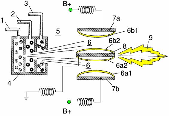
Fig.2A is a side cross-sectional view.
Fig.2B is a frontal view from the operative end.
Fig.2C is an exploded view of an individual injector.
Fig.3 and Fig.3A show the side and frontal cross-sectional views of an alternatively configured injector.
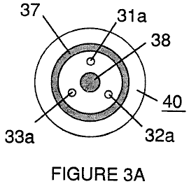
Fig.4 shows a disk array of injectors.
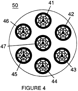
Fig.5 shows the resonance electrical circuit including the injector.
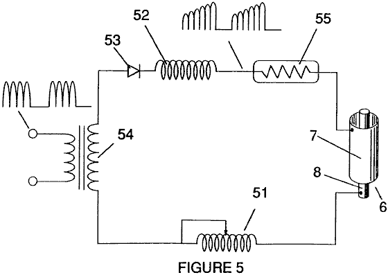
Fig.6 depicts the inter-relationship of the electrical and fuel distribution components of an injector system.
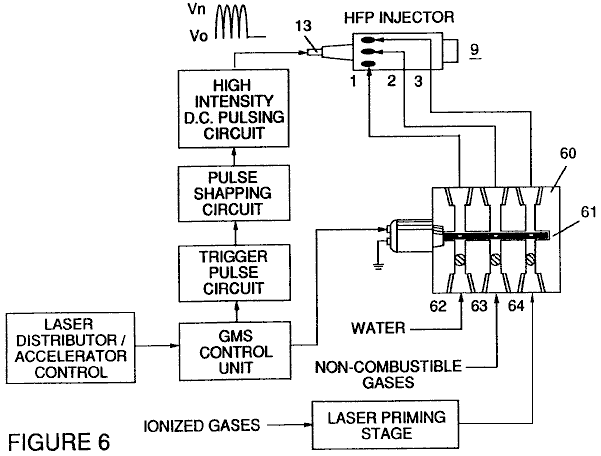
Although I refer to an “injector” in this document, the invention relates not only to the physical configuration of an injector apparatus, but also to the overall process and system parameters determined in the apparatus to achieve the release of thermal energy. In a basic outline, an injector regulates the introduction of process constituents into a combustion zone and sets up a fuel mixture condition permitting combustion. That combustion condition is triggered simultaneously with injector operation in real-time correspondence with control parameters for the process constituents.
In the fuel mixture condition which is created by the injector, water (H20) is atomised into a fine spray and mixed with 1 ionised ambient air gasses and 2 other non-combustible gasses such as nitrogen, argon and other rare gasses, and water vapour. (Exhaust gas produced by the combustion of hydrogen with oxygen is a non-combustible water vapour. This water vapour and other inert gasses resulting from combustion may be recycled from an exhaust outlet in the injector system, back into the input mixture of non-combustible gasses.) The fuel mix is introduced at a consistent flow rate maintained under a predetermined pressure. In the triggering of the condition created by the injector, the conversion process described in my patent no. 4,936,961 and co-pending application serial no. 07/460,859 is set off spontaneously on a “micro” level in a predetermined reaction zone. The injector creates a mixture, under pressure in a defined zone of water, ionised gasses and non-combustible gasses. Pressure is an important factor in the maintenance of the reaction condition and causes the water/gas mixture to become intimately mixed, compressed and destabilised to produce combustion when activated under resonance conditions of ignition. In accordance with the earlier mentioned conversion process of my patent and application, when water is subjected to a resonance condition water molecules expand and distend; electrons are ejected from the water molecule and absorbed by ionised gasses and the water molecule, thus destabilised, breaks down into its elemental components of hydrogen (H2) and oxygen (O) in the combustion zone. The hydrogen atoms released from the molecule provide the fuel source in the mixture for combustion with oxygen. The present invention is an application of that process and is outlined in Table 1:
Table 1
Injector
Mixture + Process conditions = Thermal Energy
(1) Water Mist (1) Release Under (1) Heat
pressure into
and Combustion Zone or
and (2) Internal
Combustion
(2) Ionised Gas (2) Resonance utilising Engine
the dielectric (Explosive
property of water force)
as a capacitor
and or
and (3) Jet Engine
(3) Non-combustible (3) Unipolar pulsing or
Gas at high voltage
(4) Other application
The process occurs as water mist and gasses under pressure are injected into, and intimately mixed in the combustion zone and an electrically polarised zone. In the electrically polarised zone, the water mixture is subjected to a unipolar pulsed direct current voltage which is tuned to achieve resonance in accordance with the electrical, mass and other characteristics of the mixture as a dielectric in the environment of the combustion zone. The resonant frequency will vary according to the injector configuration and depends upon the physical characteristics, such as the mass and volume of the water and gasses in the zone. As my prior patents and application point out, the resonant condition in the capacitative circuit is determined by the dielectric properties of water: (1) as the dielectric in a capacitor formed by adjacent conductive surfaces, and (2) as the water molecule itself is a polar dielectric material. At resonance, current flow in the resonant electrical circuit will be minimised and voltage will peak.
The injector system provides a pressurised fuel mixture for subjection to the resonant environment of the voltage combustion zone as the mixture is injected into the zone. In a preferred embodiment, the injector includes concentrically nested serial orifices, one for each of the three constituent elements of the fuel mixture. (It may be feasible to combine and process non-combustible and ionised gasses in advance of the injector. In this event, only two orifices are required, one for the water and the other for the combined gasses.) The orifices disperse the water mist and gasses under pressure into a conically shaped activation and combustion zone.
Fig1A shows a transverse cross-section of an injector, in which, supply lines for water 1, ionised gas 2, and non-combustible gas 3, feed into a distribution disk assembly 4 which has concentrically nested orifices. The fuel mixture passes through a mixing zone 5, and a voltage zone 6, created by electrodes 7a and 7b (positive) and 8 (negative or ground). Electrical field lines are shown as 6a1 and 6a2 and 6b1 and 6b2. Combustion (i.e. the oxidation of hydrogen) occurs in the zone 9. Ignition of the hydrogen can be primed by a spark or may occur spontaneously as a result of the exceptionally high volatility of hydrogen and its presence in a high-voltage field.

Although the mixing zone, the voltage zone and the combustion zone are mentioned separately in this explanation, they are not in fact physically separated, as can be seen from Fig.1. In the zone(s), there is produced an “excited” mixture of vaporised water mist, ionised gasses and other non-combustible gasses, all of which have been instantaneously released from under high pressure. Simultaneously, the released mixture in the zone, is exposed to a pulsed voltage at a frequency corresponding to electrical resonance. Under these conditions, outer-shell electrons of atoms in the water molecule are de-stabilised and molecular time-share is interrupted. Thus, the gas mixture in the injector zone is subjected to physical, electrical and chemical interactive forces which cause a breakdown of the atomic bonding forces of the water molecule.
Process parameters are determined, based on the size of a particular injector. In an injector sized appropriately for use to provide a fuel mixture to a conventional cylinder in a passenger vehicle car engine, the injector may resemble a conventional spark plug. In such an injector, the water orifice is 0.1 to 0.15 inch in diameter; the ionised gas orifice is 0.15 to 0.2 inch in diameter, and the non-combustible gas orifice is 0.2 to 0.25 inch in diameter. In such a configuration, the serial orifices increase in size from the innermost orifice, as appropriate in a concentric configuration. As noted above, it is desirable to maintain the introduction of the fuel components at a constant rate. Maintaining a back-pressure of about 125 pounds per square inch for each of the three fuel gas constituents appears to be satisfactory for a “spark-plug” injector. In the pressurised environment of the injector, spring-loaded one-way check valves in each supply line, such as 14 and 15, maintain pressure during pulse off times.
Voltage zone 6 surrounds the pressurised fuel mixture and provides an electrically charged environment of pulsed direct current in the range from about 500 to 20,000 volts and more, at a frequency tuned into the resonant characteristic of the mixture. this frequency will typically lie within the range from about 20 KHz to about 50 KHz, dependent, as noted above, on the mass flow of the mixture from the injector and the dielectric property of the mixture. In a spark-plug sized injector, the voltage zone will typically extend longitudinally about 0.25 to 1.0 inch to permit sufficient dwell time of the water mist and gas mixture between the conductive surfaces 7 and 8 which form a capacitor so that resonance occurs at a high-voltage pulsed frequency, and combustion is triggered. In the zone, an energy wave which is related to the resonant pulse frequency, is formed. The wave continues to pulse through the flame in the combustion zone. The thermal energy produced is released as heat energy. In a confined zone such as a piston/cylinder engine, gas detonation under resonant conditions, produces explosive physical power.
In the voltage zone, the time-share ratio of the hydrogen and oxygen atoms comprising the individual water molecules in the water mist, is upset in accordance with the process explained in my patent no. 4,936,961 and application serial no. 07/460,859. Namely, the water molecule, which is itself a polar structure, is distended or distorted in shape by being subjected to the polar electric field in the voltage zone. The resonant condition induced in the molecule by the unipolar pulses, upsets the molecular bonding of shell electrons such that the water molecule, at resonance, breaks apart into its constituent atoms. In the voltage zone, the water molecules are excited into an ionised state, and the pre-ionised gas component of the fuel mixture, captures the electrons released from the water molecule. In this manner, at the resonant condition, the water molecule is destabilised and the constituent atomic elements of the molecule 2H and O, are released and the released hydrogen atoms are available for combustion. the non-combustible gasses in the fuel mixture, reduce the burn rate of hydrogen to that of a hydrocarbon fuel such as gasoline (petrol) or kerosene (paraffin), from its normal burn rate which is about 2.5 times that of gasoline. Hence the presence of non-combustible gasses in the fuel mixture, moderates the energy release and the rate at which the free hydrogen and oxygen molecules combine in the combustion process.
The combustion process does not occur spontaneously so the conditions in the zone must be fine-tuned carefully to achieve an optimum input flow rate for water and the gasses corresponding to the maintenance of a resonant condition. The input water mist and gasses may likewise be injected into the zone in a physically pulsed (on/off) manner corresponding to the resonance achieved. In an internal combustion engine, the resonance of the electrical circuit and the physical pulsing of the input mixture may be required to be related to the combustion cycle of the reciprocating engine. In this regard, one or two conventional spark plugs may require a spark cycle tuned in correspondence to the conversion cycle resonance, so that combustion of the mixture will occur. Thus, the input flow, conversion rate and combustion rate are interrelated and optimally, each should be tuned in accordance with the circuit resonance at which conversion occurs.
The injection system of the present invention is suited to retrofit applications in conventionally fuelled gasoline and diesel internal combustion engines and conventionally fuelled jet aircraft engines.
Example 1
Figs 2A, 2B and 2C illustrate a type of injector useful, among other things, as a fuel source for a conventional internal combustion engine. In the cross-section of Fig.2A, reference numerals corresponding to the identifying numerals used in Fig.1 show a supply line for water 1, leading to first distribution disc 1a and supply line for ionised gas 2, leading to second distribution disc 2a. In the cross-section, the supply line for non-combustible gas 3 leading to distribution disc 3a, is not illustrated, however, its location as a third line should be self evident. The three discs comprise distribution disc assembly 4. The supply lines are formed in an electrically insulating body 10, surrounded by electrically conductive sheath/housing 11 having a threaded end segment 12.
A central electrode 8, extends the length of the injector. Conductive elements 7a and 7b (7a and 7b depict opposite sides of the diameter in the cross-section of a circular body), adjacent threaded section 12 and electrode 8, form the electrical polarisation zone 6 adjacent to combustion zone 9. An electrical connector 13 may be provided at the other end of the injector. (In this document, the term “electrode” refers to the conductive surface of an element forming one side of a capacitor.) In the frontal view of Fig.2B, it is seen that each disc making up the distribution disc assembly 9, includes a plurality of micro-nozzles 1a1, 2a1, 3a1, etc. for the injection of the water and gasses into the polarisation/voltage and combustion zones. The exploded view of Fig.2C shows another view of the injector and additionally depicts two supply line inlets 1 and 2, the third not being shown because of the inability of representing the uniform 1200 separation of three lines in a two-dimensional drawing.
In the injector, water mist (forming droplets in the range, for example, of from 10 to 250 microns and above, with size being related to voltage intensity) is injected into the fuel-mixing and polarising zone by way of water spray nozzles 1a1. The tendency of water to form a “bead” or droplet is a parameter related to droplet mist size and voltage intensity. ionised air gasses and non-combustible gasses, introduced through nozzles 2a1 and 3a1, are intermixed with the expelling water mist to form a fuel-mixture which enters into voltage zone 6 where the mixture is exposed to a pulsating, unipolar, high-intensity voltage field (typically 20,000 volts at 50 Hz or above, at the resonant condition in which current flow in the circuit (amps) is reduced to a minimum) created between electrodes 7 and 8.
Laser energy prevents discharge of the ionised gasses and provides additional energy input into the molecular destabilisation process which occurs at resonance. It is preferable that the ionised gasses be subjected to laser (photonic energy) activation prior to their introduction into the zone(s); although, for example, a fibre optic conduit may be useful to channel photonic energy directly into the zone. However, heat generated in the zone may affect the operability of such an alternate configuration. The electrical polarisation of the water molecule and a resonant condition occurs to destabilise the molecular bonding of the hydrogen and oxygen atoms. Combustion energy is then released by spark ignition.
To ensure proper flame projection and subsequent flame stability, pumps for the ambient air, non-combustible gas and water, introduce these components to the injector under static pressure up to and beyond 125 pounds per square inch.
Flame temperature is regulated by controlling the volume flow-rate of each fluid-media in direct relationship to applied voltage intensity. To elevate flame temperature, fluid displacement is increased while the volume flow rate of non-combustible gasses is maintained or reduced and the applied voltage amplitude is increased. To lower flame temperature, the fluid flow rate of non-combustible gasses is increased and pulse voltage amplitude is lowered. To establish a predetermined flame temperature, the fluid media and applied voltage are adjusted independently. The flame-pattern is further maintained as the ignited, compressed, and moving gasses are projected under pressure from the nozzle ports in distribution disc assembly 4 and the gas expands in the zone and is ignited.
In the voltage zone, several functions occur simultaneously to initiate and trigger thermal energy yield. Water mist droplets are exposed to high intensity pulsating voltage fields in accordance with an electrical polarisation process which separates the atoms of the water molecule and causes the atoms to experience electron ejection. The polar nature of the water molecule which facilitates the formation of minute droplets in the mist, appears to cause a relationship between the droplet size and the voltage required to effect the process, i.e. the greater the droplet size, the higher the voltage required. The liberated atoms of the water molecule interact with laser-primed ionised ambient air gasses to cause a highly energised and destabilised mass of combustible gas atoms to ignite thermally. Incoming ambient air gasses are laser primed and ionised when passing through a gas processor, and an electron extraction circuit (Fig.5) captures and consumes in sink 55, ejected electrons, and prevents electron flow into the resonant circuit.
In terms of performance, reliability and safety, ionised air gasses and water fuel liquid do not become volatile until the fuel mixture reaches the voltage and combustion zones. Injected non-combustible gasses retard and control the combustion rate of hydrogen during gas ignition.
In alternate applications, laser-primed ionised liquid oxygen and laser-primed liquid hydrogen stored in separate fuel tanks, can be used in place of the fuel mixture, or liquefied ambient air gasses alone with water can be substituted as a fuel source.
The injector assembly is design variable and is retro-fittable to fossil fuel injector ports conventionally used in jet/rocket engines, grain dryers, blast furnaces, heating systems, internal combustion engines and the like.
Example 2
A flange-mounted injector is shown in cross-section in Fig.3 which shows the fuel mixture inlets and illustrates an alternative three-nozzle configuration leading to the polarisation (voltage) and combustion zones in which one nozzle 31a, 32a and 33a is provided for each of the three gas mixtures, and connected to supply lines 31 and 32 (33 is not shown). Electrical polarisation zone 36 is formed between electrode 38 and surrounding conductive shell 37. The capacitative element of the resonant circuit is formed when the fuel mixture, acting as a dielectric, is introduced between the conductive surfaces of 37 and 38. Fig.3A is a frontal view of the operative end of the injector.
Example 3
Multiple injectors may be arranged in a gang as shown in Fig.4 in which injectors 40, 41, 42, 43, 44, 45, 46, 47, 48 and 49 are arranged concentrically in an assembly 50. Such a ganged array is useful in applications having intensive energy requirements such as jet aircraft engines and blast furnaces.
Example 4
The basic electrical system utilised in the invention is depicted in Fig.5 showing the electrical polarisation zone 6 which receives and processes the water and gas mixture as a capacitive circuit element in a resonant charging circuit formed by inductors 51 and 52 connected in series with diode 53, pulsed voltage source 54, electron sink 55 and zone 6 formed from conductive elements 7 and 8. In this manner, electrodes 7 and 8 in the injector, form a capacitor which has electrical characteristics dependent on the dielectric media (e.g. the water mist, ionised gasses and non-combustible gasses) introduced between the conductive elements. Within the macro-dielectric media, however, the water molecules themselves, because of their polar nature, can be considered micro-capacitors.
Example 5
Fuel distribution and management systems useful with the injector of this application are described in my co-pending applications for patent; PCT/US90/6513 and PCT/US90/6407.
A distribution block for the assembly is shown in Fig.6. In Fig.6 the distribution block pulses and synchronises the input of the fuel components in sequence with the electrical pulsing circuit. The fuel components are injected into the injector ports in synchronisation with the resonant frequency, to enhance the energy wave pulse extending from the voltage zone through the flame. In the configuration of Fig.6, the electrical system is interrelated to distribution block 60, gate valve 61 and separate passageways 62, 63 and 64 for fuel components. The distributor produces a trigger pulse which activates a pulse-shaping circuit that forms a pulse having a width and amplitude determined by resonance of the mixture and establishes a dwell time for the mixture in the zone to produce combustion..
As in my referenced application regarding control and management and distribution systems for a hydrogen-containing fuel gas produced from water, the production of hydrogen gas is related to pulse frequency on/off time. In the system shown in Fig.6, the distributor block pulses the fluid media introduced to the injector in relationship to the resonant pulse frequency of the circuit and to the operational on/off gate pulse frequency. In this manner, the rate of water conversion (i.e. the rate of fuel produced by the injector) can be regulated and the pattern of resonance in the flame controlled.
Patent WO 92/07861
2nd November 1990 Inventor:
CONTROL AND
DRIVER CIRCUITS FOR A HYDROGEN GAS FUEL PRODUCING CELL
The major difficulty in using Stan’s low-current Water Fuel Cell (recently reproduced by Dave Lawton and shown in Chapter 10) is the issue of keeping the cell continuously at the resonant frequency point. This patent application shows the Stan’s circuitry for doing exactly that, and consequently, it is of major importance.
ABSTRACT
A control circuit for a capacitive resonant cavity water capacitor cell (7) for the production of a hydrogen containing fuel has a resonant scanning circuit co-operating with a resonance detector and PLL circuit to produce pulses. The pulses are fed into the primary transformer (TX1). The secondary transformer (TX2) is connected to the resonant cavity water capacitor cell (7) via a diode and resonant charging chokes (TX4, TX5).
This invention relates to electrical circuit systems useful in the operation of a Water Fuel Cell including a water capacitor/resonant cavity for the production of a hydrogen containing fuel gas, such as that described in my United States Letter Patent No. 4,936,961 “Method for the Production of a Fuel Gas” issued on 26th June 1990.
In my Letters Patent for a “Method for the Production of a Fuel Gas”, voltage pulses applied to the plates of a water capacitor tune into the dielectric properties of the water and attenuate the electrical forces between the hydrogen and oxygen atoms of the molecule. The attenuation of the electrical forces results in a change in the molecular electrical field and the covalent atomic bonding forces of the hydrogen and oxygen atoms. When resonance is achieved, the atomic bond of the molecule is broken, and the atoms of the molecule disassociate. At resonance, the current (amp) draw from a power source to the water capacitor is minimised and voltage across the water capacitor increases. Electron flow is not permitted (except at the minimum, corresponding to leakage resulting from the residual conductive properties of water). For the process to continue, however, a resonant condition must be maintained.
Because of the electrical polarity of the water molecule, the fields produced in the water capacitor respectively attract and repel the opposite and like charges in the molecule, and the forces eventually achieved at resonance are such that the strength of the covalent bonding force in the water molecule (which are normally in an electron-sharing mode) disassociate. Upon disassociation, the formerly shared bonding electrons migrate to the hydrogen nuclei, and both the hydrogen and oxygen revert to net zero electrical charge. The atoms are released from the water as a gas mixture.
In the invention herein, a control circuit for a resonant cavity water capacitor cell utilised for the production of a hydrogen-containing fuel gas is provided.
The circuit includes an isolation means such as a transformer having a ferromagnetic, ceramic or other electromagnetic material core and having one side of a secondary coil connected in series with a high speed switching diode to one plate of the water capacitor of the resonant cavity and the other side of the secondary coil connected to the other plate of the water capacitor to form a closed loop electronic circuit utilising the dielectric properties of water as part of the electronic resonant circuit. The primary coil of the isolation transformer is connected to a pulse generation means. The secondary coil of the transformer may include segments which form resonant charging choke circuits in series with the water capacitor plates.
In the pulse generation means, an adjustable resonant frequency generator and a gated pulse frequency generator are provided. A gate pulse controls the number of the pulses produced by the resonant frequency generator sent to the primary coil during a period determined by the gate frequency of the second pulse generator.
The invention also includes a means for sensing the occurrence of a resonant condition in the water capacitor / resonant cavity, which when a ferromagnetic or electromagnetic core is used, may be a pickup coil on the transformer core. The sensing means is interconnected to a scanning circuit and a phase lock loop circuit, whereby the pulsing frequency to the primary coil of the transformer is maintained at a sensed frequency corresponding to a resonant condition in the water capacitor.
Control means are provided in the circuit for adjusting the amplitude of a pulsing cycle sent to the primary coil and for maintaining the frequency of the pulsing cycle at a constant frequency regardless of pulse amplitude. In addition, the gated pulse frequency generator may be connected to a sensor which monitors the rate of gas production in the cell and controls the number of pulses from the resonant frequency generator sent to the cell in a gated frequency in correspondence with the rate of gas production. The sensor may be a gas pressure sensor in an enclosed water capacitor resonant cavity which also includes a gas outlet. The gas pressure sensor is connected to the circuit to determine the rate of gas production with respect to ambient gas pressure in the water capacitor enclosure.
Thus, a comprehensive control circuit and it’s individual components for maintaining and controlling the resonance and other aspects of the release of gas from a resonant cavity water cell is described here and illustrated in the drawings which depict the following:
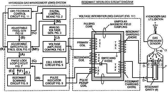
Fig.1 is a block diagram of an overall control circuit showing the interrelationship of sub-circuits, the pulsing core / resonant circuit and the water capacitor resonant cavity.
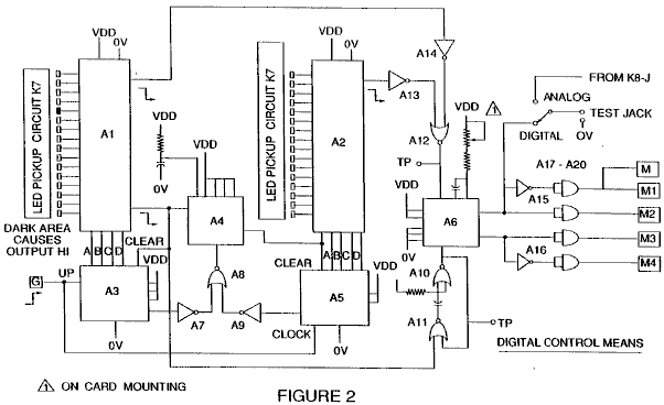
Fig.2 shows a type of digital control circuit for regulating the ultimate rate of gas production as determined by an external input. (Such a control circuit would correspond, for example, to the accelerator in a car, or the thermostat control in a building).
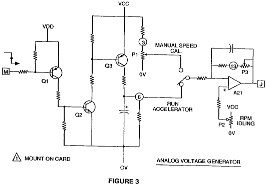
Fig.3 shows an analog voltage generator.
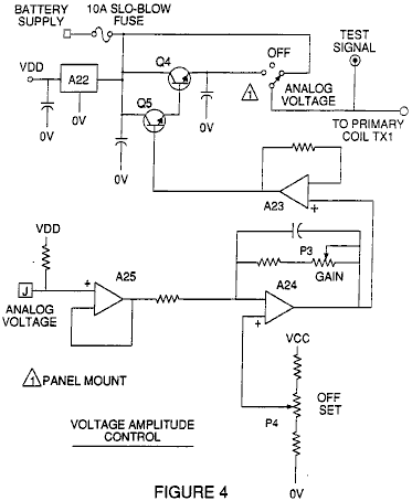
Fig.4 is a voltage amplitude control circuit interconnected with the voltage generator and one side of the primary coil of the pulsing core.
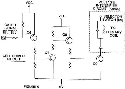
Fig.5 is the cell driver circuit that is connected with the opposite side of the primary coil of the pulsing core. Figures 6 to 9 form the pulsing control circuitry:
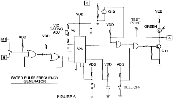
Fig.6 is a gated pulse frequency generator.
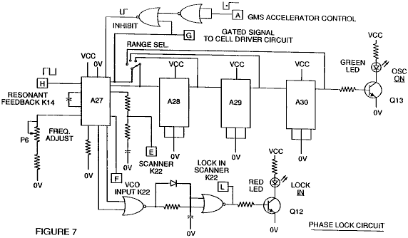
Fig.7 is a phase lock circuit.
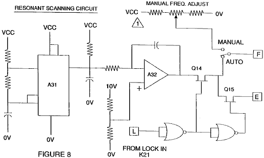
Fig.8 is a resonant scanning circuit
Fig.9 is the pulse indicator circuit.
These four circuits control the pulses transmitted to the resonant-cavity / Water Fuel Cell capacitor.
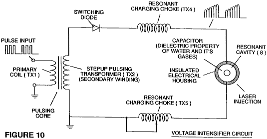
Fig.10 shows the pulsing core and the voltage intensifier circuit which forms the interface between the control circuit and the resonant cavity.
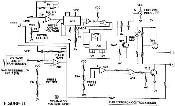
Fig.11 is a gas feedback control circuit
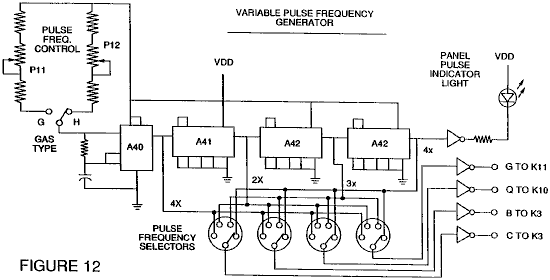
Fig.12 is an adjustable frequency generator circuit.
The circuits are interconnected as shown in Fig.1 and to the pulsing core voltage intensifier circuit of Fig.10, which, among other things, isolates the water capacitor electrically so that it becomes an electrically isolated cavity for the processing of water in accordance with it’s dielectric resonance properties. By reason of this isolation, power consumption in the control and driving circuits is minimised when resonance occurs, and current demand is minimised as voltage is maximised in the gas production mode of the water capacitor / Fuel Cell.
The reference letters “A” through “M” and “M1” show, with respect to each separate circuit shown, the point at which a connection in that circuit is made to another of the circuits shown.
In the invention, the water capacitor is subjected to a duty pulse which builds up in the resonant charging choke coil and then collapses. This occurrence allows a unipolar pulse to be applied to the Fuel Cell capacitor. When a resonant condition of the circuit is locked-in by the circuit, current leakage is held to a minimum as the voltage which creates the dielectric field tends to infinity. Thus, when high voltage is detected upon resonance, the phase-lock-loop circuit, which controls the cell driver circuit, maintains the resonance at the detected (or sensed) frequency.
The resonance of the water capacitor cell is affected by the volume of water in the cell. The resonance of any given volume of water contained in the water capacitor cell is also affected by “contaminants” in the water which act as a damper. For example, with a potential difference of 2,000 to 5,000 volts applied to the cell, a current spike or surge may be caused by inconsistencies in the water characteristics which cause an out-of-resonance condition which is remedied instantaneously by the control circuits.
In the invention, the adjustable frequency generator, shown in Fig.12, tunes in to the resonant condition of the circuit which includes the water cell and the water inside it. The generator has a frequency capability of 0 to 10 KHz and tunes into resonance typically at a frequency of 5 KHz in a typical 3-inch long water capacitor formed from a 0.5 inch rod inside a 0.75 inch inside-diameter cylinder. At start up, in this example, current draw through the water cell will measure about 25 milliamps; however, when the circuit finds a tuned resonant condition, the current drops down to a 1 to 2 milliamp leakage condition.
The voltage to the capacitor water cell increases according to the turns of the winding and the size of the coils, as in a typical transformer circuit. For example, if 12 volts is sent to the primary coil of the pulsing core and the secondary coil resonant charging choke ratio is 30 to 1, then 360 volts is sent to the capacitor water cell. The number of turns is a design variable which controls the voltage of the unipolar pulses sent to the capacitor.
The high-speed switching diode, shown in Fig.10, prevents charge leaking from the charged water in the water capacitor cavity, and the water capacitor as an overall capacitor circuit element, i.e. the pulse and charge status of the water/capacitor never pass through an arbitrary ground. the pulse to the water capacitor is always unipolar. The water capacitor is electrically isolated from the control, input and driver circuits by the electromagnetic coupling through the core. The switching diode in the Voltage Intensifier Circuit (Fig.10) performs several functions in the pulsing. The diode is an electronic switch which determines the generation and collapse of an electromagnetic field to permit the resonant charging choke(s) to double the applied frequency and it also allows the pulse to be sent to the resonant cavity without discharging the “capacitor” therein. The diode is, of course, selected in accordance with the maximum voltage encountered in the pulsing circuit. A 600 PIV (“Peak Inverse Volts”) fast switching diode, such as an NVR 1550, has been found to be useful in this circuit.
The Voltage Intensifier Circuit of Fig.10 also includes a ferromagnetic or ceramic ferromagnetic pulsing core capable of producing electromagnetic flux lines in response to an electrical pulse input. The flux lines affect both the secondary coil and the resonant charging choke windings equally. Preferably, the core is of a closed loop construction. The effect of the core is to isolate the water capacitor and to prevent the pulsing signal from going below an arbitrary ground and to maintain the charge of the already charged water and water capacitor.
In the pulsing core, the coils are preferably wound in the same direction to maximise the additive effect of the electromagnetic field in them. The magnetic field of the pulsing core is synchronised with the pulse input to the primary coil. The potential from the secondary coil is introduced to the resonant charging choke(s) series circuit elements which are subjected to the same synchronous applied electromagnetic field, simultaneously with the primary pulse.
When resonance occurs, control of the gas output is achieved by varying the time of duty gate cycle. The transformer core is a pulse frequency doubler. In a figurative explanation of the workings of the fuel gas generator water capacitor cell, when a water molecule is “hit” by a pulse, electron time-share is effected and the molecule is charged. When the time of the duty cycle is changed, the number of pulses that “hit” the molecules in the fuel cell is modified correspondingly. More “hits” result in a greater rate of molecular disassociation.
With reference to the overall circuit of Fig.1, Fig.3 receives a digital input signal, and Fig.4 shows the control circuit which applies 0 to 12 volts across the primary coil of the pulsing core. Depending on design parameters of primary coil voltage and other factors relevant to core design, the secondary coil of the pulsing core can be set up for a predetermined maximum, such as 2,000 volts.
The cell driver circuit shown in Fig.5, allows a gated pulse to be varied in direct relation to voltage amplitude. As noted above, the circuit of Fig.6 produces a gate pulse frequency. The gate pulse is superimposed on the resonant frequency pulse, to create a duty cycle that determines the number of discrete pulses sent to the primary coil. For example, assuming a resonant pulse of 5 KHz, a 0.5 KHz gating pulse with a 50% duty cycle, will allow 2,500 discrete pulses to be sent to the primary coil, followed by an equal time interval in which no pulses are passed through. The relationship of resonant pulse to the gate pulse is determined by conventional signal addition/subtraction techniques.
The phase lock loop circuit shown in Fig.7 allows the pulse frequency to be maintained at a predetermined resonant condition sensed by the circuit. Together, the circuits of Fig.7 and Fig.8, determine an output signal to the pulsing core until the peak voltage signal sensed at resonance is achieved.
A resonant condition occurs when the pulse frequency and the voltage input attenuates the covalent bonding forces of the hydrogen and oxygen atoms of the water molecule. When this occurs, current leakage through the water capacitor is minimised. The tendency of voltage to maximise at resonance, increases the force of the electric potential applied to the water molecules, which ultimately disassociate into atoms.
Because resonances of different waters, water volumes and capacitor cells vary, the resonant scanning circuit of Fig.8 scans frequency from high to low and back to high, until a signal lock is achieved. The ferromagnetic core of the voltage intensifier circuit transformer, suppresses electron surge in an out-of-resonance condition of the fuel cell. In an example, the circuit scans at frequencies from 0 Hz to 10 KHz and back to 0 Hz. In water having contaminants in the range of 1 part per million to 20 parts per million, a 20% variation in resonant frequency is encountered. depending on water flow rate into the fuel cell, the normal variation range is about 8% to 10%. For example, iron in well water affects the status of molecular disassociation. Also, at a resonant condition, harmonic effects occur. In a typical operation of the cell with a representative water capacitor described below, at a frequency of about 5 KHz, with unipolar pulses from 0 to 650 volts, at a sensed resonant condition in the resonant cavity, on average, the conversion into gas occurs at a rate of about 5 US gallons (19 litres) of water per hour. To increase the rate, multiple resonant cavities can be used and/or the surfaces of the water capacitor can be increased, however, the water capacitor cell is preferably small in size. A typical water capacitor may be formed from a 0.5 inch diameter stainless steel rod and a 0.75 inch inside-diameter cylinder which extends over the rod for a length of 3 inches.
The shape and size of the resonant cavity may vary. Larger resonant cavities and higher rates of consumption of water in the conversion process require higher frequencies up to 50 KHz and above. The pulsing rate, to sustain such high rates of conversion, must be increased correspondingly.
From the above description of the preferred embodiment, other variations and modifications of the system disclosed will be evident to those skilled in the art.
STEPHEN MEYER
Patent application
MLS-HYDROXYL FILLING STATION
This is a patent application from Stephen Meyer, brother of the late Stan Meyer. While this application mentions filling stations, it is clear that the design is aimed at use in vehicles with internal combustion engines. I believe that the impedance-matching interface between the alternator and the cell electrodes is particularly important. The water-splitter cell uses sets of three pipes in a concentric array which results in small gaps between the innermost, middle and outer pipe. Stephen refers to these three electrode pipes as a “wave-guide”, so please bear that in mind when reading this patent application. Stephen uses the word “hydroxyl” to refer to the mixture of hydrogen and oxygen gases produced by electrolysis of water. Other people use the word “hydroxy” to describe this mixture, so they should be considered interchangeable.
The operation of this system as described here, calls for the generating power to be removed when the gas pressure in the generating chambers reaches 5 psi. The gas is then pumped into a pressure chamber where the pressure ranges from 40 psi to 80 psi, at which point the compressor is powered down and the excess gas vented to some external storage or using device. It is not until this is completed that the power is applied again to the generating chambers. May I remark that, in my opinion, there is no need to remove the power from at generating chambers at any time when this system is in operation, since all that that does is to lower the generating capacity, unless of course, the production rate is so high that it exceeds the level of demand.
ABSTRACT
The usefullness of this system, it’s configuration, design and operation, are the keystone of a new type of automation: the production of hydroxyl gases from renewable sources.
BACKGROUND OF THE INVENTION
Fuel Cell and auto industries have been looking for methods and apparatus that can supply a source of hydrogen and oxygen for its new hybrid industry. This invention is such a device.
SUMMARY OF THE INVENTION
The invention is a computerised, automatic, on-site/mobile hydroxyl gas producing filling station which allows the products being produced to be used, either by the hydrogen fuel cells installed in automobiles, trucks, buses, boats and land-based generating applications, or in any internal combustion engine.
BRIEF DESCRIPTION OF THE DRAWINGS
Fig.1 shows the configuration of the components which go to make up the MLS-hydroxyl Filling Station.
Fig.2 shows the software display which the operator uses to monitor and control the production of hydroxy gases and heat.
Fig.3 shows the methods, configuration, and apparatus used in the hydroxyl producing cell system 120.
Fig.4 shows the electronic impedance-matching circuits 102, connected between the dual three-phase synchronised generators (110A and 110B in Fig.3) and each of the electrodes or “waveguide” arrays 132 in cell 120 of Fig.3. Note that only generator A is depicted in Fig.4 as being connected to arrays A, B and C using PC cards 1 to 3. generator B is connected to arrays D, E and F using cards 4 to 6.
Fig.5 Shows the signals emitted by each of the impedance-matching circuits (102 in Fig.4 mounted on cards 1 to 6) which are applied to each of the cylinder arrays (132 in Fig.3) installed in hydroxyl cell 120. These sets of signals with their offset phase relationship, frequencies and amplitudes, are the driving forces producing the hydroxy gases in cell 120 of Fig.3.
Fig.6 shows the high-frequency ringing signal which is produced between points T1 and T2 in the impedance-matching circuit 102 in Fig.4. It is this ringing which enhances the production of the hydroxyl gas in cell 120 of Fig.3.
DETAILED DESCRIPTION OF THE DRAWINGS
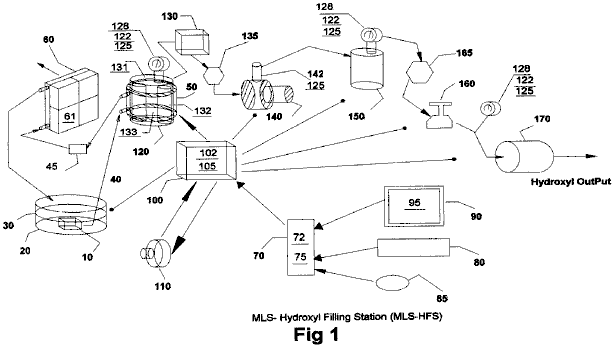
The heat-removing section in Fig.1 consists of a liquid bath 30 and its container 20, a liquid circulating pump 10, conveying-conduits 40, cooling chamber 50 attached to hydroxyl generating cell 120, filter 45, radiator 60 and cooling fans 61 attached to it.
The automatic-control section in Fig.1 consists of a computer 70, software program 75, video monitor 90 and it’s graphic operator display 95 (Fig.2), pointer 85, keyboard 80, interface card 72, and Input/Output controller 100 with it’s driver electronics cards 102 and 105.
Dual three-phase power sources 110 and impedance-matching circuits 102, provide the power needed to drive the hydroxyl cell 120.
The remaining apparatus is used to convey the gases from cells 120, through liquid trap 130, through gas flow restriction valve 135, elevate its gas pressures through compressor 140, transfer them to storage tank 150, then deliver the gases through safety cut off 165, regulators 160 and through flash-back arrestor 170 for external delivery.

Fig.2 shows the layout and functions of the operator control display 95 of program 75 in Fig.1. It consists of cell temperature indicator 230, vacuum controller 240, high-pressure tank indicator 250, delivery controller 260, delivery regulated-pressure indicator 265 and related alarm/status indicators 270. Also, software control buttons are provided to start 280, stop 290, clear data 292, change setting 294 and the testing of equipment and their sequences 296.
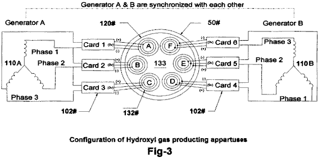
Fig.3 shows the configuration of our proprietary hydroxyl-producing apparatus 120 consisting of dual three-phase power source 110, impedance matching electronic circuits 102 and gas converter devices 132 submerged in a bath of water 133 in cell 120. The drawing also shows the water jacket 50 surrounding the cell 120 that helps lower its temperature and allows more production of the hydroxyl gases at higher voltage signals as shown in Fig.5.
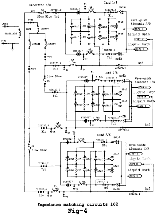
Fig.4 shows the electrical circuits 102, used to drive the gas converting arrays (132 in Fig.3) submerged in a bath of water 133 in cell 120. Fig.4 shows three identical circuits connected to each of the three-phase signals from one half of the dual three-phase generator 110A in Fig.3. The circuits 102, convert the AC signal from each phase of 110 into a modulated signal as depicted by Fig.5. These signals are then coupled to the triple array elements 132, (Inside, Middle and Outside) by alternating the connection between the Inside and Outside elements of the arrays (132 in Fig.3).
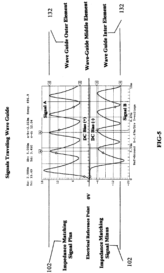
Fig.5 shows the composite signals applied to each of the arrays (132 in Fig.3) submerged in the water bath 133 in cell 120, and indicates the differential voltages used in the hydroxyl producing process. Note that the Middle wave-guide element is used as the electrical reference point for both the Outside and Inside elements of array 132. It is this composite signal applied to the surface of the stainless steel elements in array 132 submerged in water bath 133, heat allows the ions from the elements in array 132 to cross its water surface barriers 133 and contribute to the hy-droxyl production. Note the DC bias voltage +,- on either side of the centre electrical reference point 0V. It is this bias voltage being modulated by multi-polarity differential signals from 102, that contributes to the wave-guide action of arrays 132. Also, the frequency of the waveform shown in Fig.5 is adjusted to match the electrical wavelength of the arrays 132 of Fig.3 and the impedance of water bath 133.
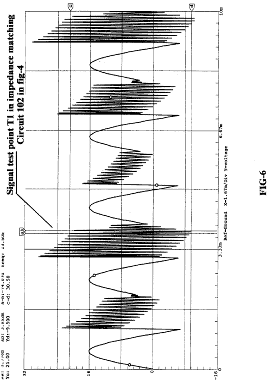
Fig.6 shows the high-frequency ringing signals which contribute to the operation of the hydroxyl production. just as a tuning fork rings when struck by a hammer, so do the wave-guide elements in array 132 immersed in the hydroxyl-generating liquid 133 when struck by the electrical signals shown in Fig.5 and Fig.6, coming from the impedance-matching circuits 102 shown in Fig.4.
Brief Description of Sequences
This invention is a computerised Hydroxyl Gas producing filling station “MLS-HFS” designed to provide automatic control of its on-site gas production and delivery.
The MLS-HFS shown in Fig.1, is a hydroxyl gas and heat generating system which uses a renewable source of liquid supply 30 such as water. It uses a computer control program 75 with display interface 95, for the monitoring, adjusting and controlling of the electronic and hardware apparatus and process logic. The electronic circuits 102 mounted in driver 100, control the production of the gases and heating while circuit 105 controls the process and routeing of the hydroxyl gas.
The system consists of a low-pressure hydrolyser cell 120 in Fig.1, a liquid trap 130, an adjustable flow-restriction valve 135, high-pressure vacuum pump 140, and check valve 142 installed in 140. It also contains a high-pressure storage tank 150, an alarm/low-pressure cut-off valve 165, gas regulator 160, flashback arrestor 170, over-pressure safety release valves 125, pressure gauges 128, analogue pressure-sending units 122 installed on cell 120, and tank 150 at the regulating side of regulator 160. Also, 125 is installed on Compressor 140 high-pressure output. The computer controller 70, monitor 90, keyboard 80, interface I/O card 72 and software position pointer 85, are used to control the production process, using electronic driver 100 through it’s PC boards 105 and their attached control devices. The power to the cell-driving circuits 102, installed in driver 100, is supplied from a dual three-phase isolated power source 110. The amplitude, signal phases and frequency from this power source is controlled by signal adjustments coming from the computer 70.
Detailed Description
Sequence of Operation
The system shown in Fig.1 is monitored and controlled by the software program 75, computer 70, monitor 90, keyboard 80, pointer 85, and display interface 95 in Fig.2.
The software program has five main functions, namely: to purge the system of ambient air, check and test for any equipment malfunctions, prepare the system for production, monitor and control the current activities of the production process, and the safety shutdown of the system if alarms are detected.
During the initial installation, and again after any repairs, the total system is purged using the vacuum pump 140, using manual procedures to ensure that all ambient air has been removed from the system. Before the system is put into service, the operator can test the operation of the system by using the graphic display. The main functions of the testing is to ensure that the temperature electronics 131 attached to the hydroxyl cells 120, transferring compressor 140 and analogue pressure sensors 122 mounted on cells 120, high-pressure tank 150 and the discharge side of regulator 160 used for control and monitoring, are working properly. the operator can then activate the Run Sequence of the program 75 via the start software button 280 in Fig.2 on graphic display 95.
During the initial startup phase of the system, the computer program will configure the system for the purge sequence. this sequence allows the vacuum pump 140 to draw down the hydroxyl cells 120 liquid trap 130 coupled to flow-restriction valve 135, to remove all ambient air from them. Once the program has done this and detected no leaks in the system, it then prepares the system for gas production by switching the gas flow from cells 120 to high-pressure tank 150 and on to the output flashback protector 170.
The program starts it’s production sequence by turning on the cooling system pump 10 which is submerged in the liquid bath 30, contained in vessel 20. The cooling liquid is pumped through the cooling jacket 50 which is attached to the outside of cells 120, through filter 45 and then through an air-cooled radiator 60. Fans attached to the radiator are turned on for cooling.
Next, the computer turns on the dual three-phase power source 110, which supplies operating power to the frequency, phase-shifting, signal amplitude and impedance-matching circuits coupled to the hydroxyl generating cells.
The result of this is just like the operation of a radio transmitter matching it’s signal to the air via the antenna impedance. Fig.3 shows the relationship of this configuration to arrays 132, water bath 133 and Signals (Fig.5 and Fig.6).
While the power source 110 is operating, the computer 70 is monitoring the pressure 122 and temperature 131 of hydroxyl cells 120. When the cell pressure reaches a typical level of 5 pounds per square inch, the power source is turned off and compressor 140 is turned on the pump the gas into pressure tank 150. When the pressure in the hydroxyl cells 120 is drawn down to near zero, the compressor is turned off and the power to the gas generating cells is turned back on again, to repeat the cycle.
The production cycle is repeated until tank 150 reaches a pressure of, typically, 80 psi, at which time the computer enables the output pressure regulator 160 which is typically set to operate at 40 psi, for the delivery of the hydroxyl gas to some external storage system or device. During this operation, the computer program handles all switching and displays the current status and any alerts or warning messages for the operator on the graphical display 95.
Impedance-Matching
Circuit 102:
The impedance-matching circuits 102 in Fig.4, convert the sinewave signals coming from the three-phase power source (110 in Fig.3) into multi-polarity differential signals (Fig.5) which are applied to the triple wave-guide cluster arrays 132 A, 132B, 132C, 132D, 132E and 132F installed in cell 120.
It is this converted signal, along with the phase relationship of the power source 110 and the triple wave-guide elements in cluster 132 submerged in water bath 133, which produce the hydroxyl gases. It is important to note that not only is the gas produced between the elements in the array, but also between each array installed in the cell - see the phase relationship of array A-B-C shown in Fig.3. Also note that the array elements themselves are supplying many of the ions needed for the production of the gases.
Sequence
of Hydroxyl Gas Generation:
Once the hydroxyl-generating cell 120 has been purged of ambient air and the production routing completed (Fig.1), the dual three-phase power source 110 is activated, supplying frequency, amplitude and phase signals to the impedance-matching circuitry 102. The converted signals from 102 are then applied to cell array 132 for processing. It is the combination of the impedance-matching circuits signal transformations (as shown in Fig.5 and Fig.6), the cell configuration and materials used in arrays 132, and the rotational phase relationship between arrays AD, BE and CF and the submersion of these arrays in a bath of water 133, that allows this system to produce large amounts of hydroxyl gases. The computer program 75 and it’s graphic display 95, is used by the operator to adjust the rate of gas production and set the upper limit to which the low-pressure cell 120 will charge.
After the cell 120 has reached its upper pressure cut-off limit (typically 5 psi), the power source 110 is turned off, enabling the compressor 140 to start its draw-down and transfer of the gases to the high-pressure tank 150. When the pressure in the cell 120 reaches a low-level limit (near zero psi), 140 stops its charging cycle of 150. Check valve 142 which is installed in 140, prevents any back flow of gases to 120 from high-pressure tank 150. The power source 110 is then turned back on to repeat the cycle. These charging cycles continue until the high-pressure tank 150 reaches it’s upper pressure limit (typically 80 psi), at which point the hydroxyl production is stopped. As the gases in the high-pressure tank are being used or transferred to some external storage system, the pressure in 150 is monitored at the output of pressure-regulator 160, until the low-pressure limit for this tank is reached (typically 40 psi). When this pressure level is reached, the hydroxyl gas production is started again.
During the operation of cell 120, it’s temperature is monitored to ensure that it does not exceed the “out of limits” conditions set by control 231 and monitored via the graphics display 95. If the temperature exceed the limit set, then the gas production is stopped and the computer program alerts the operator, indicating the problem. The cooling system 30 which uses water jacket 50 surrounding cell 120, helps to reduce the temperature and allows higher rates of gas production.
After extended running times, the water in cell 120 is replenished from bath 30 and filtered by 45, to help control the operating impedance of the cell.
Dr HENRY PUHARICH
Dr Andrija
Puharich (who later changed his name to Henry Puharich) reportedly drove his
motor home for hundreds of thousands of miles around
Cutting The Gordian Knot of the Great Energy Bind
by Andrija Puharich
Introduction
It is hardly necessary to weigh the value of the World Energy bank account for any sophisticated person, these days. It is grim. The oil reserves will dwindle away in a score of years or so, and the coal reserves will be gone in some twelve score years. This is not to say that the outlook is hopeless. There is an abundance of alternative energy sources, but the economics of development and exploitation present an enormous short-term strain on the world political and banking resources.
Visionary scientists tell us that the ideal fuel in the future will be as cheap as water, that it will be non-toxic both in its short-term, and in its long-term, effects, that it will be renewable in that it can be used over and over again, that it will be safe to handle, and present minimal storage and transportation problems and costs. And finally that it will be universally available anywhere on earth. What is this magical fuel, and why is it not being used? The fuel is water. It can be used in its fresh water form. It can be used in its salt water form. It can be used in its brackish form. It can be used in its snow and ice form. When such water is decomposed by electrolytic fission into hydrogen and oxygen gases, it becomes a high energy fuel with three times the energy output which is available from an equivalent weight of high grade gasoline.
Then why is water not being used as a fuel? The answer is simple - it costs too much with existing technology to convert water into hydrogen and oxygen gases. The basic cycle of using water for fuel is described in the following two equations, familiar to every high school student of Chemistry:
H2O Electrolysis + 249.68 BTU DG ® H2 + (1/2)O2 per mole of water..............(1)
(1 mole = 18 gm). This means that it requires 249.688 BTU of energy (from electricity) to break water by electrolysis into the gases hydrogen and oxygen.
H2 + (1/2)O2 + catalyst ® H2O - DH 302.375 BTU per mole of water..............(2)
This means that 302.375 BTU of energy (heat or electricity) will be released when the gases, hydrogen and oxygen, combine. The end product (the exhaust) from this reaction is water. Note that more energy (under ideal conditions) is released from combining the gases than is used to free them from water. It is know that under ideal conditions it is possible to get some 20% more energy out of reaction (2) above, then it takes to produce the gases of reaction (1) above. Therefore, if reaction (1) could be carried out at 100% efficiency, the release of energy from reaction (2) in an optimally efficient engine (such as a low temperature fuel cell), there would be a net energy profit which would make the use of water as a fuel an economically feasible source of energy .
The cost of producing hydrogen is directly related to the cost of producing electricity. Hydrogen as produced today is generally a by-product of off-peak-hour electrical production in either nuclear or hydroelectric plants. The electricity thus produced is the cheapest way of making hydrogen. We can compare the cost of production of electricity and the cost of producing hydrogen. The following table is adapted from Penner whose data source is based on Federal Power Commission, and American Gas Association Figures of 1970 and on a 1973 price evaluation (just before the OPEC oil price escalation.)
Table 1: Relative Prices in Dollars per 106 BTU
|
Cost Component |
Electricity |
Electrolytically-Produced H |
|
Production |
2.67 (b) |
2.95 to 3.23 (b) |
|
Transmission |
0.61 |
0.52 (c) |
|
Distribution |
1.61 |
0.34 |
|
Total Cost |
$4.89 |
$3.81 to $4.09 |
If we compare only the unit cost of production of electricity vs Hydrogen from the above table:
106 BTU H2 / 106 BTU El = $3.23 / $2.67, or 20.9% higher cost, H2
It must also be noted that the price of natural gas is much cheaper than either electricity or hydrogen, but because of the price fluctuations due to recent deregulation of gas it is not possible to present a realistic figure. In the opinion of Penner, if the hydrogen production cost component of its total cost could be reduced three fold, it would become a viable alternate energy source. In order to achieve such a three-fold reduction in production costs, several major breakthroughs would have to occur.
1. Endergonic Reaction A technological breakthrough which permits 100% conversion efficiency of water by electrolysis fission into the two gases, Hydrogen as fuel and Oxygen as oxidant.
2. Hydrogen Production in Situ A technological breakthrough which eliminates the need and cost of hydrogen liquefaction and storage, transmission, and distribution, by producing the fuel in situ, when and where needed.
3. Exergonic Reaction A technological breakthrough which yields a 100% efficient energy release from the combination of hydrogen and oxygen into water in an engine that can utilize the heat, steam, or electricity thus produced.
4. Engine Efficiency By a combination of the breakthroughs outlined above, 1, 2, and 3 utilized in a highly efficient engine to do work, it is theoretically possible to achieve a 15% to 20% surplus of energy return over energy input.
It is of interest to record that a new invention is now being developed to realise the above outlined goal of cheap, clean renewable and high grade energy. A Thermodynamic Device has been invented which produces hydrogen as fuel, and oxygen as oxidant, from ordinary water or from sea water, eliminating the cost and hazard of liquefaction, storage, transmission, and distribution. The saving of this aspect of the invention alone reduces the total cost of hydrogen by about 25%.
This Thermodynamic Device is based on a new discovery - the efficient electrolytic fission of water into hydrogen gas and oxygen gas by the use of low frequency alternating currents as opposed to the conventional use of direct current, or ultra-high frequency current today. Such gas production from water by electrolytic fission approaches 100% efficiency under laboratory conditions and measurements. No laws of physics are violated in this process.
This Thermodynamic Device has already been tested at ambient pressures and temperatures from sea level to an altitude of 10,000 feet above sea level without any loss of its peak efficiency. The device produces two types of gas bubbles; one type of bubble contains hydrogen gas; the other type contains oxygen gas. The two gases are thereafter easily separable by passive membrane filters to yield pure hydrogen gas, and pure oxygen gas.
The separate gases are now ready to be combined in a chemical fusion with a small activation energy such as that from a catalyst or an electrical spark, and yield energy in the form of heat, or steam, or electricity as needed. When the energy is released by the chemical fusion of hydrogen and oxygen, the exhaust product is clean water. The water exhaust can be released into nature and then renewed in its energy content by natural processes of evaporation, solar irradiation in cloud form, an subsequent precipitation as rain on land or sea, and then collected again as a fuel source. Or, the exhaust water can have its energy content pumped up by artificial processes such as through solar energy acting through photocells. Hence, the exhaust product is both clean and renewable. The fuel hydrogen, and the oxidant oxygen, can be used in any form of heat engine as an energy source if economy is not an important factor. But the practical considerations of maximum efficiency, dictate that a low temperature fuel cell with its direct chemical fusion conversion from gases to electricity offers the greatest economy and efficiency from small power plants of less than 5 kilowatts.
For large power plants, steam and gas turbines are the ideal heat engines for economy and efficiency. With the proper engineering effort, automobiles could be converted rather easily to use water as the main fuel source.
The Thermodynamic Device (“TD”) is made up of three principal components:
Component 1: An electrical function generator which energizes a water cell.
Component 2: The Thermodynamic Device
Component 3: A weak electrolyte.
Component 1: The Electrical Function Generator:
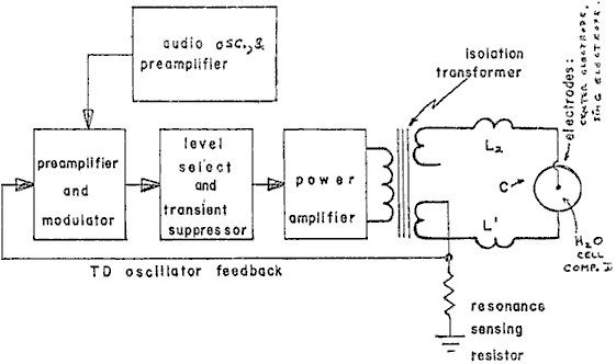
Figure 1: Signal Generator Component Block
This electronic device has a complex alternating current output consisting of an audio frequency (range 20 to 200 Hz) amplitude modulation of a carrier wave (range: 200 to 100,000 Hz). The output is connected by two wires to Component II at the center electrode, and at the ring electrode. See Fig.1. The impedance of this output signal is continuously being matched to the load which is the water solution in Component II.
Component 2: The Thermodynamic Device:
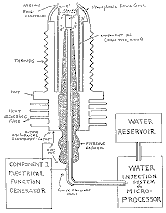
Figure 2: Thermodynamic Device
The TD is fabricated of metals and ceramic in the geometric form of a coaxial cylinder made up of a centered hollow tubular electrode which is surrounded by a larger tubular steel cylinder. These two electrodes comprise the coaxial electrode system energised by Component I. The space between the two electrodes is, properly speaking, Component III which contains the water solution to be electrolysed. The center hollow tubular electrode carries water into the cell, and is further separated from the outer cylindrical electrode by a porous ceramic vitreous material. The space between the two electrodes contains two lengths of tubular Pyrex glass, shown in Figures 2 and 3. The metal electrode surface in contact with the water solution are coated with a nickel alloy.
Component 3: The weak electrolyte water solution:
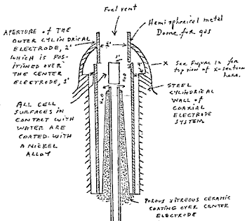
Figure 3: The Water Cell Section of Component 2
This consists of the water solution, the two glass tubes, and the geometry of the containing wall of Component 2. It is the true load for Component 1, and its electrode of Component 2.
The Component 3 water solution is more properly speaking, ideally a 0.1540 M Sodium Chloride solution, and as such, it is a weak electrolyte. In Figure 4 we show the hypothetical tetrahedral structure of water molecule, probably in the form in which the complex electromagnetic waves of Component 1 to see it. The center of mass of this tetrahedral form is the oxygen atom. The geometric arrangement of the p electrons of oxygen probably determine the vectors i (L1) and i (L2) and i (H1) and i (H2) which in turn probably determine the tetrahedral architecture of the water molecule. The p electron configuration of oxygen is shown in Figure 5. Reference to Figure 4, shows that the diagonal of the right side of the cube has at its corner terminations, the positive charge hydrogen (H+) atoms; and that the left side of the cube diagonal has at its corners, the lone pair electrons, (e-). It is to be further noted that this diagonal pair has an orthonormal relationship.
Figure 4: The Water Molecule in Tetrahedral Form:
Hydrogen bonding occurs only along the four vectors pointing to the four vertices of a regular tetrahedron, and in the above drawing we show the four unit vectors along these directions originating from the oxygen atoms at the center. i(H1) and i(H2) are the vectors of the hydrogen bonds formed by the molecule i as a donor molecule. These are assigned to the lone pair electrons. Molecules i are the neighboring oxygen atoms at each vertex of the tetrahedron.
Figure 5: Electron Orbitals
3. Electrothermodynamics
We will now portray the complex electromagnetic wave as the tetrahedral water molecule sees it. The first effect felt by the water molecule is in the protons of the vectors, i (H1) and i (H2). These protons feel the 3-second cycling of the amplitude of the carrier frequency and its associated side bands as generated by Component 1. This sets up a rotation moment of the proton magnetic moment which one can clearly see on the XY plot of an oscilloscope, as an hysteresis loop figure. However, it is noted that this hysteresis loop does not appear in the liquid water sample until all the parameters of the three components have been adjusted to the configuration which is the novel basis of this device. The hysteresis loop gives us a vivid portrayal of the nuclear magnetic relaxation cycle of the proton in water.
The next effect felt by the water molecule is the Component 1 carrier resonant frequency, Fo. At the peak efficiency for electrolysis the value of Fo is 600 Hz +/- 5 Hz.
This resonance however is achieved through control of two other factors. The first is the molal concentration of salt in the water. This is controlled by measuring the conductivity of the water through the built-in current meter of Component 1. There is maintained an idea ratio of current to voltage where I/E = 0.01870 which is an index to the optimum salt concentration of 0.1540 Molal.
The second factor which helps to hold the resonant which helps to hold the resonant frequency at 600 Hz is the gap distance of Y, between the centre electrode, and the ring electrode of Component 2.
This gap distance will vary depending on the size scale of Component 2, but again, the current flow I, is used to set it to the optimal distance when the voltage reads between 2.30 (rms) volts, at resonance Fo, and at molal concentration, 0.1540. The molal concentration of the water is thus seen to represent the electric term of the water molecule and hence its conductivity.
The amplitude modulation of the carrier gives rise to side bands in the power spectrum of the carrier frequency distribution. It is these side bands which give rise to an acoustic vibration of the liquid water, and it is believed, also to the tetrahedral water molecule. The importance of the phonon effect - the acoustic vibration of water in electrolysis - was discovered in a roundabout way. Research work with Component 1 had earlier established that it could be used for the electro-stimulation of hearing in humans. When the output of Component 1 is comprised of flat circular metal plates applied to the head of normal hearing humans, it was found that they could hear pure tones and speech. Simultaneously, acoustic vibration could also be heard by an outside observer with a stethoscope placed near one of the electrodes on the skin. It was observed that the absolute threshold of hearing could be obtained at 0.16 mW (rms), and by calculation that there was an amplitude of displacement of the eardrum of the order of 10-11 meter and a corresponding amplitude of the cochlear basilar membrane of 10-13 meter. Corollary to this finding, I was able to achieve the absolute reversible threshold of electrolysis at a power level of 0.16 mW (rms). By carrying out new calculations, I was able to show that the water was being vibrated with a displacement of the order of 1 Angstrom unit ( = 10-10 meters). This displacement is of the order of the diameter of the hydrogen atom. Thus it is possible that the acoustic phonons generated by audio side bands of the carrier are able to vibrate particle structures within the unit water tetrahedron.
We now turn to the measurement problem with respect to efficiency of electrolysis. There are four means which can be used to measure the reactant product of water electrolysis. For simple volume measurements, one can use a precision nitrometer such as the Pregl type. For both volume and quantitative analysis one can use the gas chromatography with thermal conductivity detector. For a continuous flow analysis of both volume and gas species the mass spectrometer is very useful. For pure thermodynamic measurements the calorimeter is useful. In our measurements, all four methods were examined, and it was found that the mass spectrometer gave the most flexibility and the greatest precision. In the next section we will describe our measurement using the mass spectrometer.
Protocol
4. Methodology for the Evaluation of the Efficiency of Water Decomposition by Means of Alternating Current Electrolysis
Introduction
All systems used today for the electrolysis of water into hydrogen as fuel, and oxygen as oxidant apply direct current to a strong electrolyte solution. These systems range in efficiency from 50% to 71%. The calculation of energy efficiency in electrolysis is defined as follows:
"The energy efficiency is the ratio of the energy released from the electrolysis products formed (when they are subsequently used) to the energy required to effect electrolysis."
The energy released by the exergonic process under standard conditions is
H2(g) + (1/2) O2(g) ® H2O = 3 02.375 BTU
which is 68.315 Kcal/mol. or, 286,021 Joules/mol, and is numerically equal to the enthalphy charge (DH) for the indicated process. On the other hand, the minimum energy (or useful work input) required at constant temperature and pressure for electrolysis equals the Gibbs free energy change (DG).
Penner shows that there is a basic relation derivable from the first and second laws of thermodynamics for isothermal changes which shows that
DG = DH - T DS .......... (2)
where DS represents the entropy change for the chemical reaction and T is the absolute temperature.
The Gibbs free energy change (DG) is also related to the voltage (e) required to implement electrolysis by Faraday's equation:
e = (DG / 23.06 n ) volts .......... (3)
where DG is in Kcal/mol, and n is the number of electrons (or equivalents) per mole of water electrolysed and has the numerical value 2 in the equation (endergonic process),
H2O ® H2 (g) + (1/2)O2 (g) + 56.620 kcal or + 249.68 BTU .......... (4)
Therefore, according to equation (2) at atmospheric pressure, and 300OK:
DH = 68.315 kcal/mol of H2O, and
DG = 56.620 kcal / mol of H2O = 236,954 J/mol H2O for the electrolysis of liquid water.
In view of these thermodynamic parameters for the electrolysis of water into gases, hydrogen and oxygen, we can establish by Eq.(2) numeric values where,
DG = 236.954 J/mol H2O under standard conditions. Thus
n = DG (J/mol) / DGe (J/mol) = <1 .......... (5)
where DGe is the electrical energy input to H2O (1) in Joules, and DG is the Gibbs free energy of H2O. The conversion between the two quantities is one Watt second (Ws) = one Joule.
Or, in terms of gas volume, as hydrogen, produced and measured,
n = Measured H2 (cc) / Ideal H2 (cc) = <1 .......... (6)
In accordance with these general principles we present the methodology followed in evaluating the electrolytic of alternating current on H2O in producing the gases, hydrogen and oxygen. No attempt has been made to utilize these gases according to the process of Eq.(1). It is to be noted that the process
H2 (g) + (1/2)O2 (g) ® H2O (g) .......... (7)
yields only 57.796 kcal /mol. Eq.(7) shows that per mole of gases water formed at 300OK, the heat released is reduced from the 68.315 kcal/mol at Eq. (1) by the molar heat of evaporation of water at 300OK (10.5 kcal) and the overall heat release is 57.796 kcal/mol if H2O (g) is formed at 300OK.
In the following sections we describe the new method of electrolysis by means of alternating current, and the exact method and means used to measure the endergonic process of Eq.(4) and the governing Eq.(2) and Eq.(5).
5. Thermodynamic Measurement
In order to
properly couple Component 2 to a mass spectrometer, one requires a special
housing around Component 2 which will capture the gases produced, and permit
these to be drawn under low vacuum into the mass spectrometer. Therefore a
stainless steel and glass chamber was built to contain Component 2, and
provision made to couple it directly through a CO2 water-trap to the mass
spectrometer with the appropriate stainless steel tubing. This chamber is designated as Component
4. Both the mass spectrometer and
Component 4 were purged with helium and evacuated for a two hour period before
any gas samples were drawn. In this way,
contamination was minimized. The
definitive measurement were done at Gollob Analytical Services in
We now describe the use of Component 1 and how its energy output to Component 2 is measured. The energy output of Component 1 is an amplitude-modulated alternating current looking into a highly non-linear load, i.e., the water solution. Component 1 is so designed that at peak load it is in resonance across the system (Components 1, 2, and 3) and the vector diagrams show that the capacitive reactance, and the inductance reactance are almost exactly 180O out of phase with each other, and so the net power output is reactive (the dissipative power is very small). This design ensures minimum power losses across the entire output system. In the experiments to be described, the entire emphasis is placed on achieving the maximum gas yield (credit) in exchange for the minimum applied electrical energy.
The most precise way to measure the applied energy from Component 1 to Component 2 and Component 3, is to measure the power, P, in watts, W. Ideally this should be done with a precision wattmeter, but since we were interested in following the voltage and current separately, it was decided not to use the watt meter. Separate meters were used to continuously monitor the current and the volts.
This is done by precision measurement of the volts across Component 3 as root mean square (rms) volts; and the current flowing in the system as rms amperes. Precisely calibrated instruments were used to take these two measurements. A typical set of experiments using water in the form of 0.9% saline solution 0.1540 molar to obtain high efficiency hydrolysis gave the following results:
rms Current = I = 25mA to 38 mA (0.025 A to 0.038 A.)
rms Volts = E = 4.0 Volts to 2.6 Volts
The resultant ration between current and voltage is dependent on many factors such as the gap distance between the center and ring electrodes, dielectric properties of the water, conductivity properties of the water, equilibrium states, isothermal conditions, materials used, and even the pressure of clathrates. The above current and voltage values reflect the net effect of various combinations of such parameters. When one takes the product of rms current, and rms volts, one has a measure of the power, P in watts.
P = I x E = 25 mA x 4.0 volts =100 mW (0.1 W)
and P = I x E =38 mA x 2.6 volts = 98.8 mW (0.0988 W)
At these power levels (with load), the resonant frequency of the system is 600 Hz (plus or minus 5 Hz) as measured on a precision frequency counter. The waveform was monitored for harmonic content on an oscilloscope, and the nuclear magnetic relaxation cycle was monitored on an XY plotting oscilloscope in order to maintain the proper hysteresis loop figure. All experiments were run so that the power in watts, applied through Components 1, 2, and 3 ranged between 98.8 mW to 100 mW.
Since by the International System of Units 1971 (ST), one Watt-second (Ws) is exactly equal to one Joule (J), our measurements of efficiency used these two yardsticks (1 Ws = 1J) from the debit side of the measurement.
The energy output of the system is, of course, the two gases, Hydrogen (H2) and Oxygen, (1/2)O2, and this credit side was measured in two laboratories, on two kinds of calibrated instruments, namely gas chromatography machine, and mass spectrometer machine.
The volume of gases H2 and (1/2)O2 was measured as produced under standard conditions of temperature and pressure in unit time, i.e., in cubic centimeters per minute (cc/min), as well as the possibility contaminating gases, such as air oxygen, nitrogen and argon, carbon monoxide, carbon dioxide, water vapor, etc.
The electrical and gas measurements were reduced to the common denominator of Joules of energy so that the efficiency accounting could all be handled in one currency. We now present the averaged results from many experiments. The standard error between different samples, machines, and locations is at +/- 10%, and we only use the mean for all the following calculations.
2. Thermodynamic Efficiency for the Endergonic Decomposition of Liquid Water (Salininized) to Gases Under Standard Atmosphere ( 754 to 750 mm. Hg) and Standard Isothermal Conditions @ 25OC = 77OF = 298.16OK, According to the Following Reaction:
H20 (1) ® H2(g) + (1/2)O2(1) + DG = 56.620 Kcal /mole .......... (10)
As already described, DG is the Gibbs function. We convert Kcal to our common currency of Joules by the formula, One Calorie = 4.1868 Joules
DG = 56.620 Kcal x 4.1868 J = 236,954/J/mol of H2O where 1 mole = 18 gr. .......... (11)
DGe = the electrical energy required to yield an equivalent amount of energy from H2O in the form of gases H2 and (1/2)O2.
To simplify our calculation we wish to find out how much energy is required to produce the 1.0 cc of H2O as the gases H2 and (1/2)O2. There are (under standard conditions) 22,400 cc = V of gas in one mole of H2O. Therefore
DG / V = 236,954 J / 22,400 cc = 10.5783 J/cc. .......... (12)
We now calculate how much electrical energy is required to liberate 1.0 cc of the H2O gases (where H2 = 0.666 parts, and (1/2)O2 = 0.333 parts by volume) from liquid water. Since P = 1 Ws = 1 Joule , and V = 1.0 cc of gas = 10.5783 Joules, then
PV = 1 Js x 10.5783 J = 10.5783 Js, or, = 10.5783 Ws .......... (13)
Since our experiments were run at 100 mW ( 0.1 W) applied to the water sample in Component II, III, for 30 minutes, we wish to calculate the ideal (100% efficient) gas production at this total applied power level. This is,
0.1 Ws x 60 sec x 30 min = 180,00 Joules (for 30 min.). The total gas production at ideal 100% efficiency is 180 J/10.5783 J/cc = 17.01 cc H2O (g)
We further wish to calculate how much hydrogen is present in the 17.01 cc H2O (g).
17.01 cc H2O (g) x 0.666 H2 (g) = 11.329 cc H2 (g) .......... (14)
17.01 cc H2O (g) x 0.333 (1/2)O2 (g) = 5.681 cc (1/2)O2 (g)
Against this ideal standard of efficiency of expected gas production, we must measure the actual amount of gas produced under: (1) Standard conditions as defined above, and (2) 0.1 Ws power applied over 30 minutes. In our experiments, the mean amount of H2 and (1/2)O2 produced, as measured on precision calibrated GC, and MS machines in two different laboratories, where SE is +/- 10%, is,
Measured Mean = 10.80 cc H2 (g)
Measured Mean = 5.40 cc (1/2) cc (1/2)O2 (g)
Total Mean = 16.20 cc H2O (g)
The ratio, n, between the ideal yield, and measured yield,
Measured H2 (g) / Ideal H2 (g) = 10.80 cc / 11.33 cc = 91.30%
6. Alternative Method for Calculating Efficiency Based on the Faraday Law of Electrochemistry
This method is based on the number of electrons that must be removed, or added to decompose, or form one mole of, a substance of valence one. In water (H2O), one mole has the following weight:
H = 1.008 gr /mol
H = 1.008 gr /mol
O = 15.999 gr/mol
Thus, 1 mol H2O = 18.015 gr/mol
For a univalent substance, one gram/mole contains 6.022 x 10⁻²³ electrons = N = Avogadro's Number. If the substance is divalent, trivalent, etc., N is multiplied by the number of the valence. Water is generally considered to be of valence two.
At standard temperature and pressure (“STP”) one mole of a substance contains 22.414 cc, where Standard temperature is 273.15OK = 0OC = T . Standard Pressure (one atmosphere) = 760 mm Hg = P.
One Faraday (“F”) is 96,485 Coulombs per mole (univalent).
One Coulomb (“C”) is defined as:
1 N / 1 F = 6.122 x 10²³ Electrons / 96,485 C = one C
The flow of one C/second = one Ampere.
One C x one volt = one Joule second (Js).
One Ampere per second @ one volt = one Watt = one Joule.
In alternating current, when amps (I) and Volts (E) are expressed in root mean squares (rms), their product is Power in watts.
P = IE watts (
With these basic definitions we can now calculate efficiency of electrolysis of water by the method of Faraday’s electrochemistry.
The two-electron model of water requires 2 moles of electrons for electrolysis (2 x 6.022 x 1023), or two Faraday quantities (2 x 96,485 = 192,970 Coulombs).
The amount of gas produced will be:
H2 = 22,414 cc /mol at STP
(1/2)O2 = 11,207 cc / mol at STP
Gases = 33.621 cc / mol H2O (g)
The number of coulombs required to produce one cc of gases by electrolysis of water:
193,970 C / 33621 C = 5.739567 C per cc gases.
Then, 5,739 C /cc /sec = 5.739 amp/sec/cc. How many cc of total gases will be produced by 1 A/sec?
0.1742291709 cc.
How many cc of total gases will be produced by 1 A/min ?
10.45375 cc/min
What does this represent as the gases H2 and O2 ?
(1/2)O2 = 3.136438721 cc/Amp/min.
H2 = 6.2728 cc/Amp /min.
We can now develop a Table for values of current used in some of our experiments, and disregarding the voltage as is done conventionally.
1. Calculations for 100 mA per minute:
Total Gases = 1.04537 cc/min
H2 = 0.6968 cc/min
(1/2)O2 = 0.3484 cc/min
30 min. H2 = 20.9054 cc/ 30 minutes
2. Calculations for 38 mA per minute:
Total Gases = 0.3972 cc/ 30 minutes
H2 = 0.2645 cc/min
(1/2)O2 = 0.1323 cc/min
30 min. H2 = 7.9369 cc/min
3. Calculations for 25mA per minute:
30 min. H2 = 5.2263 cc/ minute
7. Conclusion
Fig.6 and Fig.7 [not available] show two of the many energy production systems that may be configured to include renewable sources and the present electrolysis technique. Figure 6 shows a proposed photovoltaic powered system using a fuel cell as the primary battery. Assuming optimum operating conditions using 0.25 watt seconds of energy from the photovoltaic array would enable 0.15 watt-seconds to be load.
Figure 7 depicts several renewable sources operating in conjunction with the electrolysis device to provide motive power for an automobile.
********************
US Patent 4,394,230 DATE 19th July 1983 INVENTOR: HENRY K. PUHARICH
METHOD AND APPARATUS FOR SPLITTING WATER MOLECULES
This is a re-worded extract from the United States Patent number 4,394,230. It describes how Henry Puharich was able to split water into hydrogen and oxygen gasses by a process which used very little input power.
ABSTRACT
Disclosed herein is a new and improved thermodynamic device to produce hydrogen gas and oxygen gas from ordinary water molecules or from seawater at normal temperatures and pressure. Also disclosed is a new and improved method for electrically treating water molecules to decompose them into hydrogen gas and oxygen gas at efficiency levels ranging between approximately 80-100%. The evolved hydrogen gas may be used as a fuel; and the evolved oxygen gas may be used as an oxidant.
Inventors: Puharich; Henry K.
(Rte. 1,
BACKGROUND OF THE INVENTION
The scientific community has long realised that water is an enormous natural energy resource, indeed an inexhaustible source, since there are over 300 million cubic miles of water on the earth's surface, all of it a potential source of hydrogen for use as fuel. In fact, more than 100 years ago Jules Verne prophesied that water eventually would be employed as a fuel and that the hydrogen and oxygen which constitute it would furnish an inexhaustible source of heat and light.
Water has been split into its constituent elements of hydrogen and oxygen by electrolytic methods, which have been extremely inefficient, by thermochemical extraction processes called thermochemical water-splitting, which have likewise been inefficient and have also been inordinately expensive, and by other processes including some employing solar energy. In addition, artificial chloroplasts imitating the natural process of photosynthesis have been used to separate hydrogen from water utilising complicated membranes and sophisticated artificial catalysts. However, these artificial chloroplasts have yet to produce hydrogen at an efficient and economical rate.
These and other proposed water splitting techniques are all part of a massive effort by the scientific community to find a plentiful, clean, and inexpensive source of fuel. While none of the methods have yet proved to be commercially feasible, they all share in common the known acceptability of hydrogen gas as a clean fuel, one that can be transmitted easily and economically over long distances and one which when burned forms water.
SUMMARY OF THE PRESENT INVENTION
In classical quantum physical chemistry, the water molecule has two basic bond angles, one angle being 104°, and the other angle being 109°28'. The present invention involves a method by which a water molecule can be energised by electrical means so as to shift the bond angle from the 104° degree. configuration to the 109° degree 28' tetrahedral geometrical configuration.
An electrical function generator (Component 1) is used to produce complex electrical wave form frequencies which are applied to, and match the complex resonant frequencies of the tetrahedral geometrical form of water. It is this complex electrical wave form applied to water which is contained in a special thermodynamic device (Component II) which shatters the water molecule by resonance into its component molecules --- hydrogen and oxygen.
The hydrogen, in gas form, may then be used as fuel; and oxygen, in gas form is used as oxidant. For example, the thermodynamic device of the present invention may be used as a hydrogen fuel source for any existing heat engine --- such as, internal combustion engines of all types, turbines, fuel cell, space heaters, water heaters, heat exchange systems, and other such devices. It can also be used for the desalination of sea water, and other water purification purposes. It can also be applied to the development of new closed cycle heat engines where water goes in as fuel, and water comes out as a clean exhaust.
For a more complete understanding of the present invention and for a greater appreciation of its attendant advantages, reference should be made to the following detailed description taken in conjunction with the accompanying drawings.
DESCRIPTION OF THE DRAWINGS:
Fig.1 is a schematic block diagram illustrating the electrical function generator, Component I, employed in the practice of the present invention:
Fig.2 is a schematic illustration of the apparatus of the present invention, including a cross sectional representation of the thermodynamic device, Component II:
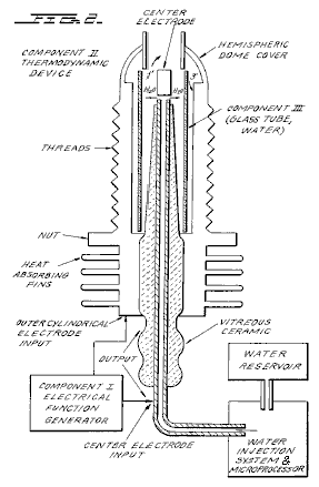
Fig.3 is a cross-sectional view of Component III of the present invention, the water cell section of Component II:
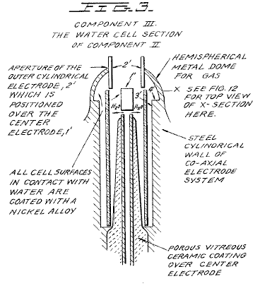
Fig.4 is an illustration of the hydrogen covalent bond:
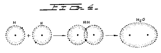
Fig.4A is an illustration of the hydrogen bond angle:

Fig.4B is an illustration of hybridised and un-hybridised orbitals:
Fig.4C is an illustration of the geometry of methane ammonia and water molecules:

Fig.5 is an illustration of an amplitude modulated carrier wave:
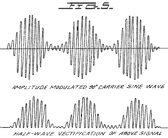
Fig.6 is an illustration of a ripple square wave:
Fig.6A is an illustration of unipolar pulses.
Fig.7 is a diagram showing ion distribution at the negative electrode:
Fig.8 is an illustration of tetrahedral bonding orbitals:
Fig.9 is an illustration of water molecules:
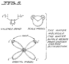
Fig.10 is an illustration of productive and non-productive collisions of hydrogen with iodine:
Fig.11 is a wave form found to be the prime characteristic for optimum efficiency:
Fig.12 is an illustration of pearl chain formation:
Fig.13 is a plot of the course of the onset of the barrier effect and the unblocking of the barrier effect:

Figs.14A, B, and C are energy diagrams for exergonic reactions:
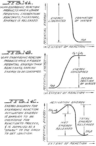
DETAILED DESCRIPTION OF INVENTION:
Section 1:
Apparatus of Invention;
The apparatus of the invention consists of three components, the Electrical Function Generator, the Thermodynamic Device, and the Water Cell.
Component I: The Electrical Function Generator;
This device has an output consisting of an audio frequency (range 20 to 200 Hz) amplitude modulation of a carrier wave (range 200 Hz to 100,000 Hz). The impedance of this output signal is continuously being matched to the load which is the second component, the thermodynamic device. The electrical function generator represents a novel application of circuitry disclosed in my earlier U.S. Pat. Nos. 3,629,521; 3,563,246; and 3,726,762, which are incorporated by reference herein. See Fig.1 for the block diagram of Component I.
Component II: The Thermodynamic Device;
The thermodynamic device is fabricated of metals and ceramic in the geometric form of coaxial cylinder made up of a central hollow tubular electrode which is surrounded by a larger tubular steel cylinder, said two electrodes comprising the coaxial electrode system which forms the load of the output of the electrical function generator, Component I. Said central hollow tubular electrode carries water, and is separated from the outer cylindrical electrode by a porous ceramic vitreous material. Between the outer surface of the insulating ceramic vitreous material, and the inner surface of the outer cylindrical electrode exists a space to contain the water to be electrolysed. This water cell space comprises the third component (Component III) of the invention. It contains two lengths of tubular Pyrex glass, shown in Fig.2 and Fig.3. The metal electrode surfaces of the two electrodes which are in contact with the water are coated with a nickel alloy.
The coaxial electrode system is specifically designed in materials and geometry to energise the water molecule to the end that it might be electrolysed. The central electrode is a hollow tube and also serves as a conductor of water to the Component III cell. The central tubular electrode is coated with a nickel alloy, and surrounded with a porous vitreous ceramic and a glass tube with the exception of the tip that faces the second electrode. The outer cylindrical electrode is made of a heat conducting steel alloy with fins on the outside, and coated on the inside with a nickel alloy. The central electrode, and the cylindrical electrode are electrically connected by an arching dome extension of the outer electrode which brings the two electrodes at one point to a critical gap distance which is determined by the known quenching distance for hydrogen. See Fig.2 for an illustration of Component II.
Component III: The Water Cell;
The water cell is a part of the upper end of Component II, and has been described. An enlarged schematic illustration of the cell is presented in FIG. 3. The Component III consists of the water and glass tubes contained in the geometrical form of the walls of cell in Component II, the thermodynamic device. The elements of a practical device for the practice of the invention will include:
(A) Water reservoir; and salt reservoir; and/or salt
(B) Water injection system with microprocessor or other controls which sense and regulate (in accordance with the parameters set forth here:
a. Carrier frequency
b. Current
c. Voltage
d. RC relaxation time constant of water in the cell
e. Nuclear magnetic relaxation constant of water
f. Temperature of hydrogen combustion
g. Carrier wave form
h. RPM of an internal combustion engine (if used)
i. Ignition control system
j. Temperature of region to be heated;
(C) An electrical ignition system to ignite the evolved hydrogen gas fuel.
The important aspects of Component III are the tubular vitreous material, the geometry of the containing walls of the cell, and the geometrical forms of the water molecules that are contained in the cell. A further important aspect of the invention is the manipulation of the tetrahedral geometry of the water molecule by the novel methods and means which will be more fully described in the succeeding sections of this specification.
The different parts of a molecule are bound together by electrons. One of the electron configurations which can exist is the covalent bond which is achieved by the sharing of electrons. A molecule of hydrogen gas, H2 is the smallest representative unit of covalent bonding, as can be seen in Fig.4. The molecule of hydrogen gas is formed by the overlap and pairing of 1s orbital electrons. A new molecular orbit is formed in which the shared electron pair orbits both nuclei as shown in Fig.4. The attraction of the nuclei for the shared electrons holds the atoms together in a covalent bond.
Covalent bonds have direction. The electronic orbitals of an uncombined atom can change shape and direction when that atom becomes part of a molecule. In a molecule in which two or more covalent bonds are present the molecular geometry is dictated by the bond angles about the central atom. The outermost lone pair (non-bonding) electrons profoundly affect the molecular geometry.
The geometry of water illustrates this concept. In the ground state, oxygen has the outer shell configuration:
1s2 2s2 2p2x 2p1y 2p1z
In water the 1s electrons from two hydrogen atoms bond with the 2py and 2pz electrons of oxygen. Since p orbitals lie at right angles to each other (see Fig.4A), a bond angle of 90° might be expected. However, the bond angle is found experimentally to be approximately 104°. Theoretically this is explained by the effect of lone pair electrons on hybridised orbitals.
Combined or hybrid orbitals are formed when the excitement of 2s electrons results in their promotion from the ground state to a state energetically equivalent to the 2p orbitals. The new hybrids are termed sp3 from the combination of one s and three p orbitals (See Fig.4B). Hybrid sp3 orbitals are directed in space from the centre of a regular tetrahedron toward the four corners. If the orbitals are equivalent the bond angle will be 109°28' (See Fig.15) consistent with the geometry of a tetrahedron. In the case of water two of the orbitals are occupied by non-bonding electrons (See Fig.4C). There is greater repulsion of these lone pair electrons which orbit only one nucleus, compared to the repulsion of electrons in bonding orbitals which orbit two nuclei. This tends to increase the angle between non-bonding orbitals so that it is greater than 109°, which pushes the bonding orbitals together, reducing the bond angle to 104°. In the case of ammonia, NH3 where there is only one lone pair, the repulsion is not so great and the bond angle is 107°. Carbon forms typical tetrahedral forms and components the simplest being the gas methane, CH4 (See Fig.4C and Fig.8). The repulsion of lone pair electrons affects charge distribution and contributes to the polarity of a covalent bond. (See Fig.16)
As demonstrated in succeeding sections of this patent specification, a significant and novel aspect of this invention is the manipulation, by electronic methods and means, of the energy level of the water molecule, and the transformation of the water molecule into, and out of, the geometrical form of the tetrahedron. This is made possible only by certain subtle dynamic interactions among the Components I, II, and III of the present invention.
Section 2:
Electrodynamics (Pure Water);
The electrodynamics of Components I, II, and III, will be described individually and in interaction during the progress of pure water reaction rate in time. The reactions of saline water will be described in Section 3. It is to be noted that the output of Component I automatically follows the seven stages (hereinafter Stages A-F) of the reaction rate by varying its parameters of resonant carrier frequency, wave form, current voltage and impedance. All the seven states of the reaction herein described are not necessary for the practical operation of the system, but are included in order to explicate the dynamics and novel aspects of the invention. The seven stages are applicable only to the electrolysis of pure water.
Stage A:
Dry Charging of Component II by Component I;
To make the new system operational, the Component I output electrodes are connected to component II, but no water is placed in the cell of Component III. When Component I output is across the load of Component II we observe the following electrical parameters are observed:
Range of current (I) output with (dry) load: 0 to 25 mA (milliamps) rms.
Range of voltage (E) output with (dry) load: 0 to 250 Volts (AC) rms.
There is no distortion of the amplitude modulated (AM), or of the sine wave carrier whose central frequency, fc' ranges between 59,748 Hz to 66, 221 Hz, with fc average = 62, 985 Hz
The carrier frequency varies with the power output in that fc goes down with an increase in amperes (current). The AM wave form is shown in Fig.5. It is to be noted here that the electrical function generator, Component I, has an automatic amplitude modulation volume control which cycles the degree of Amplitude Modulation from 0% to 100%, and then from 100% to 0% every 3.0 seconds. This cycle rate of 3.0 seconds corresponds to the nuclear spin relaxation time, tau/sec, of the water in Component III. The meaning of this effect will be discussed in greater detail in a later section.
In summary, the principal effects to be noted during Stage A -dry charging of Component II are as follows:
a. Tests the integrity of Component I circuitry.
b. Tests the integrity of the coaxial electrodes, and the vitreous ceramic materials of Component II and Component III.
c. Electrostatic cleaning of electrode and ceramic surfaces.
Stage B:
Initial operation of Component I, Component II, and with Component III containing pure water. There is no significant electrolysis of water during Stage B. However, in Stage B the sine wave output of Component I is shaped to a rippled square wave by the changing RC constant of the water as it is treated;
There is an `Open Circuit` reversible threshold effect that occurs in Component III due to water polarisation effects that lead to half wave rectification and the appearance of positive unipolar pulses; and
There are electrode polarisation effects in Component II which are a prelude to true electrolysis of water as evidenced by oxygen and hydrogen gas bubble formation.
Appearance of Rippled Square Waves:
Phase 1: At the end of the Stage A dry charging, the output of Component I is lowered to typical values of: I = 1 ma. E = 24V AC. fc .congruent.66,234 Hz.
Phase 2: Then water is added to the Component III water cell drop by drop until the top of the centre electrode, 1', in Fig.3 is covered, and when this water just makes contact with the inner surface of the top outer electrode at 2'. As this coupling of the two electrodes by water happens, the following series of events occur:
Phase 3: The fc drops from 66,234 Hz, to a range from 1272 Hz to 1848 Hz. The current and voltage both drop, and begin to pulse in entrainment with the water nuclear spin relaxation constant, tau =3.0 sec. The presence of the nuclear spin relaxation oscillation is proven by a characteristic hysteresis loop on the X-Y axes of an oscilloscope.
I = 0 to 0.2 mA surging at .tau. cycle
E = 4.3 to 4.8V AC surging at .tau. cycle
The sine wave carrier converts to a rippled square wave pulse which reflects the RC time constant of water, and it is observed that the square wave contains higher order harmonics. See Fig.6:
With the appearance of the rippled square wave, the threshold of hydrolysis may be detected (just barely) as a vapour precipitation on a cover glass slip placed over the Component III cell and viewed under a low power microscope.
The ‘Open Circuit’ Reversible Threshold
Effect:
Phase 4 A secondary effect of the change in the RC constant of water on the wave form shows up as a full half wave rectification of the carrier wave indicating a high level of polarisation of the water molecule in tetrahedral form at the outer electrode.
With the already noted appearance of the rippled square wave, and the signs of faint vapour precipitation which indicate the earliest stage of electrolysis, it is possible to test for the presence of a reversible hydrolysis threshold. This test is carried out by creating an open circuit between Components I and II, i.e., no current flows. This is done by lowering the water level between the two electrodes in the region --- 1' and 2' shown in Fig.3; or by interrupting the circuit between Component I and II, while the Component I signal generator is on and oscillating.
Immediately, with the creation of an `open circuit` condition, the following effects occur:
(a) The carrier frequency, fc, shifts from Phase 4 valve 1272 Hz to 1848 Hz to 6128 Hz.
(b) The current and voltage drop to zero on the meters which record I and E, but the oscilloscope continues to show the presence of the peak-to-peak (p-p) voltage, and the waveform shows a remarkable effect. The rippled square wave has disappeared, and in its place there appear unipolar (positive) pulses as follows in Fig.6A.
The unipolar pulse frequency stabilises to ca. 5000 Hz. The unipolar pulses undergo a 0 to 1.3 volt pulsing amplitude modulation with .tau. at 3.0 seconds. Thus, there exists a pure open circuit reversible threshold for water electrolysis in which the water molecules are capacitor charging and discharging at their characteristic low frequency RC time constant of 0.0002 seconds. It is to be noted that pure water has a very high dielectric constant which makes such an effect possible.
The pulsing amplitude modulation of the voltage is determined by the Hydrogen Nuclear Spin Relaxation constant of 3.0 seconds. It is to be noted that the positive pulse spikes are followed by a negative after-potential. These pulse wave forms are identical to the classic nerve action potential spikes found in the nervous system of all of the living species which have a nervous system. The fact that these unipolar pulses were observed arising in water under the conditions of reversible threshold hydrolysis has a profound significance. These findings illuminate and confirm the Warren McCulloch Theory of water "crystal" dynamics as being the foundation of neural dynamics; and the converse theory of Linus Pauling which holds that water clathrate formation is the mechanism of neural anesthesia.
Phase 5: The effects associated with reversible threshold electrolysis are noted only in passing, since they reflect events which are occurring on the electrode surfaces of Component II, the Thermodynamic Device.
A principal effect which occurs in Stage B, Phase 3, in Component II, (the thermodynamic device), is that the two electrodes undergo stages of polarisation. It has been observed in extensive experiments with different kinds of fluids in the cell of Component II , i.e., distilled water, sea water, tap water, Ringers solution, dilute suspensions of animal and human blood cells, etc. that the inner surface of the outer ring electrode at 3' in Fig.3 (the electrode that is in contact with the fluid) becomes negatively charged. Referring to Fig.7, this corresponds to the left hand columnar area marked, “Electrode .crclbar.”.
Electrode Polarisation Effects at the Interface Between Components II and III:
Concurrently with the driver pulsing of Component I at the .tau. constant cycle which leads to electrode polarisation effects in Component II, there is an action on Component III which energises and entrains the water molecule to a higher energy level which shifts the bond angle from 104° to the tetrahedral form with angle 109°28' as shown in Fig.8 and Fig.15.
This electronic pumping action is most important, and represents a significant part of the novel method of this invention for several reasons. First, the shift to the tetrahedral form of water increases the structural stability of the water molecule, thereby making it more susceptible to breakage at the correct resonant frequency, or frequencies. Second, increasing the polarisation of the water molecule makes the lone pair electrons, S- connected with the oxygen molecule more electronegative; and the weakly positive hydrogen atoms, S+ more positive. See Fig.9 and Fig.22.
As the outer electrode becomes more electrically negative, the central electrode becomes more electrically positive as will be shown. As the polarity of the water molecule tetrahedron increases, a repulsive force occurs between the two S+ apices of the water tetrahedron and the negatively charged electrode surface within the region of the Helmholtz layer, as shown in Fig.7. This effect "orients" the water molecule in the field, and is the well-known "orientation factor" of electrochemistry which serves to catalyse the rate of oxygen dissociation from the water molecule, and thereby causes the reaction rate to proceed at the lowest energy levels. See Fig.10 for an example of how the orientation factor works. Near the end of Stage B, the conditions are established for the beginning of the next stage, the stage of high efficiency electrolysis of water.
Stage C:
Generation of the complex wave form frequencies from Component I to match the complex wave form resonant frequencies of the energised and highly polarised water molecule in tetrahedral form with angles, 109°28' are carried out in Stage C. In the operation of the invention active bubble electrolysis of water is initiated following Stage B, phase 3 by setting (automatically) the output of Component I to:
I = 1 mA., E = 22V AC-rms, causing the rippled square wave pulses to disappear with the appearance of a rippled sawtooth wave. The basic frequency of the carrier now becomes, fc = 3980 Hz.
The wave form now automatically shifts to a form found to be the prime characteristic necessary for optimum efficiency in the electrolysis of water and illustrated in Fig.11. In the wave form of Fig.11, the fundamental carrier frequency, fc = 3980 Hz., and a harmonic modulation of the carrier is as follows:
1st Order Harmonic Modulation (OHM) = 7960 Hz.
2nd Order Harmonic Modulation (II OHM) = 15,920 Hz.
3rd Order Harmonic Modulation (III OHM) = 31,840 Hz.
4th Order Harmonic Modulation (IV OHM) = 63,690 Hz.
What is believed to be happening in this IV OHM effect is that each of the four apices of the tetrahedron water molecule is resonant to one of the four harmonics observed. It is believed that the combination of negative repulsive forces at the outer electrode with the resonant frequencies just described work together to shatter the water molecule into its component hydrogen and oxygen atoms (as gases). This deduction is based on the following observations of the process through a low power microscope. The hydrogen bubbles were seen to originate at the electrode rim, 4', of Fig.3. The bubbles then moved in a very orderly `pearl chain` formation centripetally (like the spokes of a wheel) toward the central electrode, 1' of Fig.3, (Fig.12 shows a top view of this effect).
Thereafter, upon lowering the output of Component I, the threshold for electrolysis of water as evidenced by vapour deposition of water droplets on a glass cover plate over the cell of Component III, is:
I = 1 mA, E = 10V so, Power = 10 mW
with all other conditions and waveforms as described under Stage C, supra. Occasionally, this threshold can be lowered to:
I = 1 ma, E = 2.6V so, Power = 2.6 mW
This Stage C vapour hydrolysis threshold effect cannot be directly observed as taking place in the fluid because no bubbles are formed --- only invisible gas molecules which become visible when they strike a glass plate and combine into water molecules and form droplets which appear as vapour.
Stage D:
Production of hydrogen and oxygen gas at an efficient rate of water electrolysis is slowed in Stage D when a barrier potential is formed, which blocks electrolysis, irrespective of the amount of power applied to Components II and III.
A typical experiment will illustrate the problems of barrier potential formation. Components I, II, and III are set to operate with the following parameters:
I = 1 ma, E = 11.2V so, Power = 11.2 mW (at the start, rising to 100 mW later)
This input to Component III yields, by electrolysis of water, approximately 0.1 cm3 of hydrogen gas per minute at one atmosphere and 289OK. It is observed that as a function of time the fc crept up from 2978 Hz to 6474 Hz over 27 minutes. The current and the voltage also rose with time. At the 27th minute a barrier effect blocked the electrolysis of water, and one can best appreciate the cycle of events by reference to Fig.13.
Stage E:
The Anatomy of the Barrier Effect:
Region A: Shows active and efficient hydrolysis
Region B: The barrier region effect can be initiated with taps of the finger, or it can spontaneously occur as a function of time.
Phase a: The current rose from 1 mA to 30 mA. The voltage fell from 22 volts to 2.5 V.
Phase b: If component II is tapped mechanically during Phase a supra --- it can be reversed as follows: The current dropped from 30 mA to 10 mA. The voltage shot up from 5 volts to over 250 volts (off scale).
Throughout ‘Phase a’ and ‘Phase b’, all hydrolysis has ceased. It was observed under the microscope that the inner surface of the outer electrode was thickly covered with hydrogen gas bubbles. It was reasoned that the hydrogen gas bubbles had become trapped in the electrostricted layer, because the water molecule tetrahedrons had flipped so that the S+ hydrogen apices had entered the Helmholtz layer and were absorbed to the electronegative charge of the electrode. This left the S- lone pair apices facing the electrostricted layer. This process bound the newly forming H+ ions which blocked the reaction
H+ + H+ + 2e ® H2 (gas)
Stage F:
Region C: It was found that the barrier effect could be unblocked by some relatively simple procedures:
(a) Reversing the output electrodes from Component I to Component II, and/or:
(b) Mechanically tapping the Component III cell at a frequency T/2 = 1.5 seconds per tap.
These effects are shown in FIG. 12 and induce the drop in barrier potential from:
I = 10 mA to 1 ma, E = 250V to 4V so, Power fell from 2.5W to 4 mW
Upon unblocking of the barrier effect, electrolysis of water resumed with renewed bubble formation of hydrogen gas.
The barrier potential problem has been solved for practical application by lowering the high dielectric constant of pure water, by adding salts (NaCl, KOH, etc.) to the pure water thereby increasing its conductivity characteristics. For optimum efficiency the salt concentration need not exceed that of sea water (0.9% salinity) in Section 3, "Thermodynamics of the Invention", it is to be understood that all water solutions described are not "pure" water as in Section B, but refer only to saline water.
Section 3:
The Thermodynamics of the Invention (Saline
Water);
Introduction: (water, hereinafter refers to saline water);
The thermodynamic considerations in the normal operations of Components I, II, and III in producing hydrogen as fuel, and oxygen as oxidant during the electrolysis of water, and the combustion of the hydrogen fuel to do work in various heat engines is discussed in this section.
In chemical reactions the participating atoms form new bonds resulting in compounds with different electronic configurations. Chemical reactions which release energy are said to be exergonic and result in products whose chemical bonds have a lower energy content than the reactants. The energy released most frequently appears as heat. Energy, like matter, can neither be created nor destroyed according to the Law of Conservation of Energy. The energy released in a chemical reaction, plus the lower energy state of the products, is equal to the original energy content of the reactants. The burning of hydrogen occurs rather violently to produce water as follows:
2H2 + O2 ® 2H2O - DH 68.315 Kcal/mol (this is the enthalpy, or heat of combustion at constant pressure) where 18 gms = 1 mol.
The chemical bonds of the water molecules have a lower energy content than the hydrogen and oxygen gases which serve at the reactants. Low energy molecules are characterised by their stability. High energy molecules are inherently unstable. These relations are summarised in the two graphs of Fig.14. It is to be noted that Fig.14B shows the endergonic reaction aspect of the invention when water is decomposed by electrolysis into hydrogen and oxygen.
Fig.14A shows the reaction when the hydrogen and oxygen gases combine, liberate energy, and re-form into water. Note that there is a difference in the potential energy of the two reactions. Fig.14C shows that there are two components to this potential energy. The net energy released, or the energy that yields net work is labelled in the diagram as “Net Energy Released”, and is more properly called the free energy change denoted by the Gibbs function, -.D.G.
The energy
which must be supplied for a reaction to achieve (burning) spontaneity is
called the “Activation Energy”. The sum of the two is the total energy
released. A first thermodynamic subtlety of the thermodynamic device of the
invention is noted in Angus McDougall's Fuel Cells, Energy Alternative Series,
The MacMillan Press Ltd.,
"The Gibbs function is defined in terms
of the enthalpy H, and the entropy S of the system:
G
= H-T S (where .tau. is the thermodynamic temperature) . A particularly important result is that for
an electrochemical cell working reversibly at constant temperature and
pressure, the electrical work done is the net work and hence,
.
D.G = -we
For this to be a reversible process, it is
necessary for the cell to be on `open circuit`, that is, no current flows and
the potential difference across the electrodes is the EMF, E. Thus,
.
D.G = -zFE
(where F is the Faraday constant --- the product of the Avogadro Constant + NA = 6.022045 x 10²³ mole-1, and the charge on the electron, e = 1.602 189 x 10-19 C --- both in SI units; and z is the number of electrons transported.) when the cell reaction proceeds from left to right."
It is to be
noted that the Activation Energy is directly related to the controlling
reaction rate process, and thus is related to the Gibbs free energy
changes. The other thermodynamic
subtlety is described by S. S. Penner in his work: Penner, S. S. and L.
Icerman, Energy, Vol, II, Non-Nuclear Energy Technologies. Addison-Wesley
Publishing Company, Inc. Revised Edition, 1977.
"It should be possible to improve the
efficiency achieved in practical electrolysis to about 100% because, under
optimal operating conditions, the theoretically-attainable energy conversion by
electrolysis is about 120% of the electrical energy input. The physical basis
for this last statement will now be considered:
"A useful definition for energy
efficiency in electrolysis is the following: the energy efficiency is the ratio
of the energy released from the electrolysis products formed (when they are
subsequently used) to the energy required to effect electrolysis. The energy
released by the process
H2
(gas) + (1/2)O2 (gas) ® H2O
(liquid)
under standard conditions (standard
conditions in this example are: (1) atmospheric pressure = 760 mm Hg and (2)
temperature = 298.16OK. = 25OC. = 77OF.) is
68.315 Kcal and is numerically equal to the enthalph change (.D.H)
for the indicated process. On the other hand, the minimum energy (or useful
work input) required at constant temperature and pressure for electrolysis
equals the Gibbs free energy change (.D.G).
There is a basic relation derivable from the first and second laws of
thermodynamics for isothermal changes, which shows that:
.D.G
= . D.H - T. D.S
where .D.S
represents the entropy change for the chemical reaction. The Gibbs free energy
change (.D.G) is also related to the
voltage (E) required to implement electrolysis by Faraday's equation, viz.
E = (.D.G/23.06n)
volts
where . D.G is
in Kcal/mol and n is the number of electrons (or equivalents) per mol of water
electrolysed and has the numerical value 2.
At atmospheric pressure and 300OK., .D.H = 68.315 Kcal/mol of H2O (i) and .D.G = 56.62 Kcal/mole of H2O (i) for the electrolysis of liquid water. Hence, the energy efficiency of electrolysis at 300OK. is about 120%.
(When) H2 (gas) and O2
(gas) are generated by electrolysis, the electrolysis cell must absorb heat
from the surroundings, in order to remain at constant temperature. It is this
ability to produce gaseous electrolysis products with heat absorption from the
surroundings that is ultimately responsible for energy-conversion efficiencies
during electrolysis greater than unity.”
Using the criteria of these two authorities, it is possible to make a rough calculation of the efficiency of the present invention.
Section 4:
Thermodynamic Efficiency of the Invention;
Efficiency is deduced on the grounds of scientific accounting principles which are based on accurate measurements of total energy input to a system (debit), and accurate measurements of total energy (or work) obtained out of the system (credit). In principle, this is followed by drawing up a balance sheet of energy debits and credits, and expressing them as an efficiency ration, e.
![]()
The energy output of Component I is an alternating current passing into a highly non-linear load, i.e., the water solution. This alternating current generator (Component I) is so designed that at peak load it is in resonance (Components I, II, III), and the vector diagrams show that the capacitive reactance, and the inductive reactance are almost exactly 180° out of phase, so that the net power output is reactive, and the dissipative power is very small. This design insures minimum power losses across the entire output system. In the experiments which are now to be described the entire emphasis was placed on achieving the maximum gas yield (credit) in exchange for the minimum applied energy (debit).
The most
precise way to measure the applied energy to Components II and III is to
measure the Power, P, in
ms Current = 25 mA to 38 mA (0.025 A to 0.038 A)
rms Volts = 4 Volts to 2.6 Volts
The resultant ratio between current and voltage is dependent on many factors, such as the gap distance between the central and ring electrodes, dielectric properties of the water, conductivity properties of the water, equilibrium states, isothermal conditions, materials used, and even the presence of clathrates. The above current and voltage values reflect the net effect of various combinations of such parameters. The product of rms current, and rms volts is a measure of the power, P in watts:
P = I x E = 25 mA x 4.0 volts = 100 mW (0.1 W)
P = I x E = 38 mA x 2.6 volts = 98.8 mW (0.0988 W)
At these power
levels (with load), the resonant frequency of the system is 600 Hz (plus or
minus 5 Hz) as measured on a precision frequency counter. The wave form was
monitored for harmonic content on an oscilloscope, and the nuclear magnetic
relaxation cycle was monitored on an X-Y plotting oscilloscope in order to
maintain the proper hysteresis loop figure. All experiments were run so that
the power in
The energy output of the system is, of course, the two gases, hydrogen (H2) and oxygen (1/2O2), and this credit side was measured in two laboratories, on two kinds of calibrated instruments, namely, a Gas Chromatography Machine, and, a Mass Spectrometer Machine.
The volume of gases, H2 and (1/2)O2, was measured as produced under standard conditions of temperature and pressure in unit time, i.e., in ccs per minute (cc/min), as well as the possibly contaminating gases, such as air oxygen, nitrogen and argon; carbon monoxide, carbon dioxide, water vapour, etc.
The electrical, and gas, measurements were reduced to the common denominator of Joules of energy so that the efficiency accounting could all be handled in common units. The averaged results from many experiments follow. The Standard Error between different samples, machines, and locations is plus or minus 10%, and only the mean was used for all the following calculations.
Section 5:
Endergonic Decomposition of Liquid Water;
Thermodynamic efficiency for the endergonic decomposition of saline liquid water into gases under standard atmosphere (754 to 750 m.m. Hg), and standard isothermal conditions @ 25OC. = 77OF. = 298.16OK., according to the following reaction:
H2O(1) ® H2 (g) + (1/2)O2 (g) + .D.G 56.620 KCal/mole
As already described, .D.G is the Gibbs function (Fig.14B). A conversion of Kcal to the common units, Joules, by the formula, One Calorie = 4.1868 Joules was made.
.D.G = 56.620 Kcal x 4.1868 J = 236,954 J/mol of H2O (1) where, 1 mole is 18 gms.
.D.G = the free energy required to yield an equivalent amount of energy from H2O in the form of the gases, H2 and (1/2)O2.
To simplify the calculations, the energy required to produce 1.0 cc of H2O as the gases, H2 and (1/2)O2 was determined. There are (under standard conditions) 22,400 cc = V, of gas in one mole of H2O. Therefore:
![]()
The electrical energy required to liberate 1.0 cc of the H2O gases (where H2 = 0.666 parts, and (1/2)O2 = 0.333 parts, by volume) from liquid water is then determined. Since P = 1 Ws = 1 Joule, and V=1.0 cc of gas = 10.5783 Joules, then:
PV = 1 x 10.5783 J = 10.5783 Ws
Since the experiments were run at 100 mW (0.1 W) applied to the water sample in Component II, III, for 30 minutes, the ideal (100% efficient) gas production at this total applied power level was calculated.
0.1 Ws x 60 sec x 30 min = 180.00 Joules (for 30 min)
The total gas production at Ideal 100% efficiency is,
180.00 J / 10.5783 J/cc = 17.01 cc H2O (g)
The amount of hydrogen present in the 17.01 cc H2O (g) was then calculated.
17.01 cc H2O (gas) x 0.666 H2 (g) = 11.329 cc H2 (g)
17.01 cc H2O (g) x 0.333 (1/2)O2 (g) = 5.681 cc (1/2)O2 (g)
Against this ideal standard of
efficiency of expected gas production, the actual amount of gas produced was
measured under: (1) standard conditions as defined above (2) 0.1 Ws power
applied over 30 minutes. In the experiments, the mean amount of H2
and (1/2)O2 produced, as measured on precision calibrated GC, and MS
machines in two different laboratories, where the S.E. is +/-10%, was,
______________________________________
Measured Mean = 10.80 cc H2
(g)
Measured Mean = 5.40 cc (1/2)O2 (g)
Total Mean = 16.20 cc H2O(g)
______________________________________
The ratio, e, between the ideal yield, and measured yield is:
![]()
Section 6:
Energy Release;
The total energy release (as heat, or electricity) from an exergonic reaction of the gases, H2 and O2, is given by:
![]()
It is possible (Penner, Op. Cit., p.128) to get a total heat release, or total conversion to electricity in a fuel cell, in the above reaction when the reactants are initially near room temperature (298.16OK.), and the reactant product (H2O) is finally returned to room temperature. With this authoritative opinion in mind, it is desirable to determine the amount of energy released (ideal) from the exergonic experiment. The total energy of 1.0 cc of H2O (1), as above is:
![]()
for H2 = 12.7687 x 0.666 = 8.509 J/0.66 cc H2 for O2 = 12.7687 x 0.333 = 4.259 J/0.33 cc (1/2)O2 The energy produced from the gases produced in the experiments in an exergonic reaction was:
16.20 cc H2O (g) x 12.7687 J/cc H2O = 206,8544 J.
The overall energy transaction can be written as:
![]()
In practical bookkeeping terms the balance of debits and credits, n = (-.D.H) - (+.D.G), so:
n = 206.8544 J - 180.0 = + 26.8544 J (surplus).
Since, in the invention, the gas is produced where and when needed, there is no additional cost accounting for liquefaction, storage, or transportation of the hydrogen fuel, and the oxygen oxidant. Therefore, the practical efficiency, is:
![]()
In practical applications, the energy output (exergonic) of the Component II System can be parsed between the electrical energy required to power the Component I System, as an isothermal closed loop; while the surplus of approximately 15% can be shunted to an engine (heat, electrical, battery, etc.) that has a work load. Although this energy cost accounting represents an ideal model, it is believed that there is enough return (approximately 15%) on the capital energy investment to yield a net energy profit that can be used to do useful work.
CONCLUSION:
From the foregoing disclosure it will be appreciated that the achievement of efficient water splitting through the application of complex electrical waveforms to energised water molecules, i.e. tetrahedral molecules having bonding angles of 109°28', in the special apparatus described and illustrated, will provide ample and economical production of hydrogen gas and oxygen gas from readily available sources of water. It is to be understood, that the specific forms of the invention disclosed and discussed herein are intended to be representative and by way of illustrative example only, since various changes may be made therein without departing from the clear and specific teachings of the disclosure. Accordingly, reference should be made to the following appended claims in determining the full scope of the method and apparatus of the present invention.
SHIGETA HASEBE
US Patent 4,105,528
8th August 1978
Inventor: Shigeta Hasebe
APPARATUS FOR
DECOMPOSITION OF AQUEOUS LIQUID
Please note
that this is a re-worded excerpt from this patent. This patent describes an electrolysis system
which it is claimed has demonstrated ten times the efficiency that Faraday
considered to be the maximum possible.
ABSTRACT
An apparatus for decomposition of liquid, in which spiral negative and positive electrodes are arranged close together but not touching. These two electrodes are supplied with power through external terminals and the electrolyte is caused to flow between the negative and positive electrodes for the electrolysis between two electrodes under the function of the potential magnetic field formed by the coil current which is generated by the electrodes with active movement of an electrolytic ion so that the electrolysis of water takes place smoothly under the spin functions of the atom and electron.
BACKGROUND AND SUMMARY OF THE INVENTION
This invention relates to an apparatus for decomposition of liquid where a flowing electrolyte is subjected to electrolysis for the production of gases.
As is well known, water is composed of hydrogen atoms and oxygen atoms. When water is sufficiently magnetised, each constitutive atom is also weakly magnetised to rotate the elementary particle in a regular direction. This rotation of the elementary particle is generally called "spin". That is, the spin function is caused by an electron, atomic nucleus, atom and even by the molecule. When a negative electrode is immersed in the electrolyte - Sodium Hydroxide (“lye”) solution - with a view to applying a voltage to it in order to cause the elementary particle to react with the electric field, the coupling state of the hydrogen with the oxygen is varied and the electrolysis is facilitated by the spin.
In the present
invention, spiral negative and positive electrodes are arranged close together
but not touching and these two electrodes are supplied with power through
external terminals and the electrolyte is caused to flow between the negative
and positive electrodes. Thus, the electrolyte is subjected to the electrolysis
between two electrodes while within a magnetic field formed by the coil current
which is generated by the electrodes with active movement of an electrolytic
ion (Na+,
It has been confirmed that the rate of the electrolysis of water using this invention is approximately 10 or more times (approximately 20 times when calculated) than that produced by conventional electrolysis.
The design of the electrolytic cell of this invention is such that the electrolyte flowing through the supply ports provided at the lower portion of the electrolytic cell is subjected to the magnetic field produced by a permanent magnet and the electrodes cause it to be further subjected to magnetic and electric fields which cause it to obtain a sufficient spin effect.
It is, therefore, a general object of the invention to provide a novel apparatus for decomposition of liquid in which an electrolyte (NaOH) solution is subjected to magnetic fields to cause electrolysis assisted by the spin of the water molecules which produces a great amount of gas with less consumption of electrical energy.
A principal object of the invention is to provide an apparatus for decomposition of liquid which has a liquid circulating system for the separation of gas and liquid in which positive and negative spiral electrodes are arranged across the flow path of the liquid and the opposite ends of the electrodes being provided with magnetic materials to augment the effect caused by the applied voltage across a liquid passing through a magnetic field caused by the positive and negative spiral electrodes, thereby to promote generation and separation of cat-ions and an-ions with a high efficiency in production of a large quantity of gases.
Other objects and advantages of the present invention will become apparent through the detailed description which follows.
BRIEF DESCRIPTION OF THE DRAWINGS
The invention will be described more in detail in the following with reference to the accompanying drawings, wherein:
Fig.1 is a partially cross-sectional schematic elevation of an apparatus in accordance with the invention;
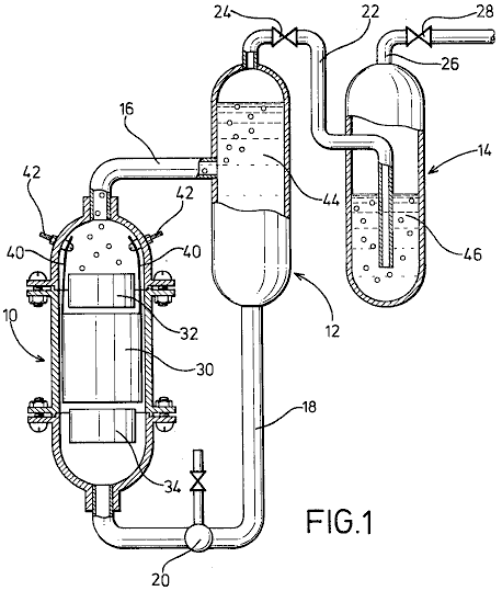
Fig.2 is a perspective view of electrodes arranged in accordance with the invention;
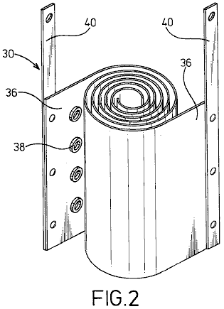
Fig.3 is a plan view of electrodes with magnetic materials.
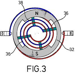
DESCRIPTION OF THE PREFERRED EMBODIMENT
In Fig.1, an electrolysis cell 10, a gas-liquid separation tank 12 and a gas-washing tank 14 are vertically arranged as shown with the electrolytic cell 10 being positioned a little lower than the tanks.
Cell 10 and tanks 12 and 14 are connected together by a delivery pipe 16 which connects the top of the electrolytic cell 10 with the middle of the gas-liquid separation tank 12. A feed-back pipe 18 containing a pump 20, is provided to connect the bottom of the gas-liquid separation tank 12, with the bottom of the electrolytic cell 10. Also provided is pipe 22, which runs from the top of the gas-liquid separation tank 12 through a valve 24 to the bottom of the gas-washing tank 14. A drain pipe 26, provided with a valve 28, is taken from the top of the gas-washing tank 14.
In the electrolytic cell 10, positive and negative spiral electrodes 30 of diameters suited to the internal diameter of the electrolytic cell 10 are arranged coaxially. At the upper and lower parts of the spiral electrodes 30 are arranged magnet rings 32 and 34 made from ferrite or similar material, positioned so that North and South poles are opposite one another to create a magnetic field which is at right angles to the axis of the electrolytic cell.
Electrodes 30 are composed of two metal strips 36 which are wound into spiral shapes with cylindrical insulating spacers 38 made of rubber or a similar material, placed between them and attached to the surface of the metal strips 36. From the metal strips 36, wires 40, are taken to the positive and negative power supply terminals, via connectors provided in the inner wall of the electrolytic cell.
The electrolytic cell 10 and the gas-liquid separation tank 12 are filled with a electrolyte 44 which is circulated by the pump 20, while the gas-washing tank 14 is filled with a washing liquid 46 to such a level that gases gushing out of the conduit 22 are thoroughly washed.
The apparatus of the present invention may be well be used for the electrolysis of flowing water for the production of hydrogen gas and oxygen gas at a high efficiency. That is to say, the electrolytic cell 10 and the gas-liquid separation tank 12 are filled with the electrolyte 44 which is caused by pump 20 to flow through a magnetic field in an vortex path in which positive and negative magnetic poles N, S of the magnets 32 and 34 face each other to produce a transverse field, and through the metal plates 36 of the vortical electrodes 30 to generate an orientation for the electrical migration of cat-ions and an-ions, causing an increased gas separation rate and enhancement of the electrolysis.
In particular, the flowing oxygen gas serves to facilitate an aeration of the electrolyte since it has varying magnetic effects as it passes through the magnetic field. The spiral electrodes 30 of this invention, create a remarkable increase in the rate of electrolysis. This is caused by the continuously decreasing space between the electrodes 30 which causes the flow velocity to increase as the flow progresses along its path. This causes turbulence which instantly removes bubbles of gas from the surface of the electrodes, allowing fresh ions full contact with the metal surfaces, thus raising the efficiency of the cell.
The spiral coiling of the electrodes also enables a very desirable reduction in the size of the cell, while increasing the electrode area and improving its contact with the electrolyte 44. There is also a relatively short migration distance of ions which also promotes rapid gas production. On the other hand, insulating spacers 38 interposed between the metal strips 36 serves to create the desired turbulence of the electrolyte passing through the cell.
The liquid circulating system for separation of gas and liquid requires no other driving unit except the circulation pump 20 to achieve separation of gas and liquid by utilising differences in water heads between cell 10 and tanks 12 and 14. In other words, a flow of gas-liquid mixture supplied from electrolytic cell 10 is fed into the gas-liquid separation tank 12 where, due to the difference in buoyancy of gases and liquid, the gas rises and is fed into the gas-washing tank 14 while the liquid moves down and is returned to the electrolytic cell 10. The washing tank 14 is filled with any convenient washing liquid 46 so that the gases gushing out of conduit 22 are thoroughly washed and fed into the drain pipe 26. Thus, the apparatus may be constructed at reduced cost and without any complexity.
As described earlier, the magnets 32 and 34 provide positive and negative magnetic poles N, S which are confronted in the annular wall for facilitating an alignment between the cross section of the flow-path of the liquid and the annular portion of the magnets 32 and 34 and a generation of a magnetic field in a direction perpendicular to that of the liquid flow, so that the liquid is forced to flow through the magnetic field.
|
Experimental data |
Value |
|
Room temperature |
200 Centigrade |
|
Atmospheric pressure |
1003 millibars |
|
Electrolyte temperature |
250 Centigrade |
|
Humidity |
43% |
|
Voltage |
2.8 Volts |
|
Current |
30 Amps |
|
Hydroxy gas production rate |
116 cc/sec. |
|
Hydrogen production per Coulomb (1A x 1 sec.) |
2.6 cc. |
|
Oxygen production per Coulomb |
1.3 cc. |
The rate of generation shown by these figures is over 20 times that which could be obtained by standard Faraday electrolysis.
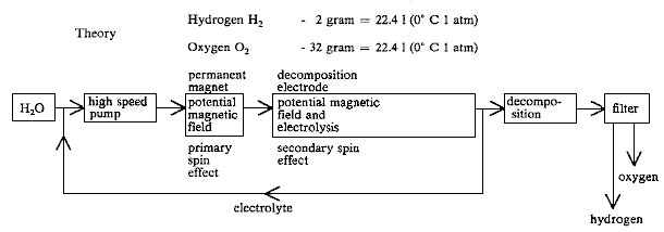
While a preferred embodiment of the invention has been illustrated by way of example in the drawings and particularly described, it will be understood that various modifications may be made in the construction and that the invention is no way limited to the embodiments shown.
STEPHEN CHAMBERS
(Xogen Power Inc.)
US Patent 6,126,794 16th July 2002 Inventor: Stephen Chambers
AN APPARATUS FOR PRODUCING ORTHOHYDROGEN AND/OR PARAHYDROGEN
This
patent describes an electrolyser system capable of running a small internal
combustion engine directly from water alone.
ABSTRACT
An
apparatus for producing orthohydrogen and/or parahydrogen. The apparatus
includes a container holding water and at least one pair of closely-spaced
electrodes arranged within the container and submerged in the water. A first
power supply provides a particular first pulsed signal to the electrodes. A
coil may also be arranged within the container and submerged in the water if
the production of parahydrogen is also required. A second power supply provides
a second pulsed signal to the coil through a switch to apply energy to the water.
When the second power supply is disconnected from the coil by the switch and
only the electrodes receive a pulsed signal, then orthohydrogen can be
produced. When the second power supply is connected to the coil and both the
electrodes and coil receive pulsed signals, then the first and second pulsed
signals can be controlled to produce parahydrogen. The container is
self-pressurised and the water within the container requires no chemical
catalyst and yet can produce the orthohydrogen and/or parahydrogen efficiently.
Heat is not generated, and bubbles do not form on the electrodes.
BACKGROUND
OF THE INVENTION
Conventional
electrolysis cells are capable of producing hydrogen and oxygen from water.
These conventional cells generally include two electrodes arranged within the
cell which apply energy to the water to thereby produce hydrogen and oxygen.
The two electrodes are conventionally made of two different materials.
However,
the hydrogen and oxygen generated in the conventional cells are generally
produced in an inefficient manner. That
is, a large amount of electrical power has to be applied to the electrodes in
order to produce the hydrogen and oxygen.
Moreover, a chemical catalyst such as sodium hydroxide or potassium
hydroxide must be added to the water to separate hydrogen or oxygen bubbles
from the electrodes. Also, the produced
gas must often be transported to a pressurised container for storage, because
conventional cells produce the gases slowly.
Also, conventional cells tend to heat up, creating a variety of
problems, including boiling of the water.
In addition, conventional cells tend to form gas bubbles on the
electrodes which act as electrical insulators and reduce the efficiency of the
cell.
Accordingly,
it is extremely desirable to produce a large amount of hydrogen and oxygen with
only a modest amount of input power.
Furthermore, it is desirable to produce the hydrogen and oxygen with
"regular" tap water and without any additional chemical catalyst, and
to operate the cell without the need for an additional pump to pressurise
it. It is also desirable to construct
both of the electrodes from the same material.
It is also desirable to produce the gases quickly, and without heat, and
without bubbles forming on the electrodes.
Orthohydrogen
and parahydrogen are two different isomers of hydrogen. Orthohydrogen is that
state of hydrogen molecules in which the spins of the two nuclei are
parallel. Parahydrogen is that state of
hydrogen molecules in which the spins of the two nuclei are antiparallel. The different characteristics of
orthohydrogen and parahydrogen lead to different physical properties. For example, orthohydrogen is highly
combustible whereas parahydrogen is a slower burning form of hydrogen. Thus, orthohydrogen and parahydrogen can be
used for different applications.
Conventional electrolytic cells make only orthohydrogen and
parahydrogen. Parahydrogen is difficult
and expensive to make by conventional means.
Accordingly,
it is desirable to produce orthohydrogen and/or parahydrogen cheaply within a
cell and to be able to control the amount of either produced by that cell. It is also desirable to direct the produced
orthohydrogen or parahydrogen to a coupled machine in order to provide a source
of energy for it.
SUMMARY
OF THE INVENTION
It
is therefore an object of the present invention to provide a cell having
electrodes and containing water which produces a large amount of hydrogen and
oxygen in a relatively small amount of time, and with a modest amount of input
power, and without generating heat.
It
is another object of the present invention for the cell to produce bubbles of
hydrogen and oxygen which do not bunch around or on the electrodes.
It
is also an object of the present invention for the cell to operate properly
without a chemical catalyst. Thus, the cell can be run using ordinary tap
water. This has the advantage of
avoiding the additional costs required for producing the chemical catalyst.
It
is another object of the present invention for the cell to be
self-pressurising. Thus avoiding the
need for an additional pump.
It
is another object of the present invention to provide a cell having electrodes
made of the same material. This material can, for example, be stainless
steel. Thus, the construction of the
cell can be simplified and construction costs reduced.
It
is another object of the present invention to provide a cell which is capable
of producing orthohydrogen, parahydrogen or a mixture thereof and can be set so
as to produce any relative amount of orthohydrogen and parahydrogen desired by
the user.
It
is another object of the invention to couple the gaseous output of the cell to
a device, such as an internal combustion engine, so that the device may be
powered from the gas supplied to it.
These
and other objects, features, and characteristics of the present invention will
be more apparent upon consideration of the following detailed description and
appended claims with reference to the accompanying drawings, wherein the same
reference numbers have been used to indicate corresponding parts in the various
figures.
Accordingly,
the present invention includes a container for holding water. At least one pair
of closely-spaced electrodes are positioned within the container and submerged
under the water. A first power supply
provides a particular pulsed signal to the electrodes. A coil is also arranged in the container and
submerged under the water. A second
power supply provides a particular pulsed signal through a switch to the
electrodes.
When
only the electrodes receive a pulsed signal, then orthohydrogen can be
produced. When both the electrodes and
coil receive pulsed signals, then parahydrogen or a mixture of parahydrogen and
orthohydrogen can be produced. The
container is self pressurised and the water within the container requires no
chemical catalyst to produce the orthohydrogen and/or parahydrogen efficiently.
BRIEF DESCRIPTION OF THE DRAWINGS
Fig.1
is a side view of a cell for producing orthohydrogen including a pair of
electrodes according to a first embodiment of the present invention;
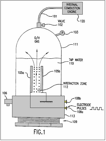
Fig.2
is a side view of a cell for producing orthohydrogen including two pairs of
electrodes according to a second embodiment of the present invention;
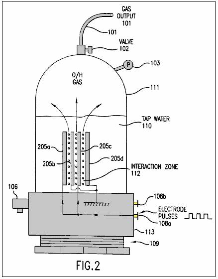
Fig.3
is a side view of a cell for producing orthohydrogen including a pair of
cylindrical-shaped electrodes according to a third embodiment of the present
invention;
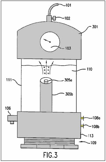
Fig.4a
is a diagram illustrating a square wave pulsed signal which can be produced by the
circuit of Fig.5 and applied to the
electrodes of Fig.1 through Fig.3;
Fig.4b
is a diagram illustrating a saw tooth wave pulsed signal which can be produced
by the circuit of Fig.5 and applied
to the electrodes of Fig.1 through Fig.3;
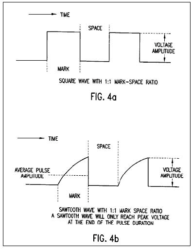
Fig.4c
is a diagram illustrating a triangular wave pulsed signal which can be produced
by the circuit of Fig.5 and applied
to the electrodes of Fig.1 through Fig.3;
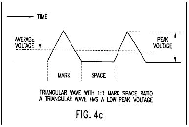
Fig.5 is an electronic circuit diagram illustrating a power supply
which is connected to the electrodes of Fig.1
through Fig.3;

Fig.6
is a side view of a cell for producing at least parahydrogen including a coil
and a pair of electrodes according to a fourth embodiment of the present
invention;
Fig.7
is a side view of a cell for producing at least parahydrogen including a coil
and two pairs of electrodes according to a fifth embodiment of the present
invention;
Fig.8 is a side view of a cell for producing at least parahydrogen
including a coil and a pair of cylindrical-shaped electrodes according to a
sixth embodiment of the present invention; and
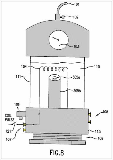
Fig.9
is as electronic circuit diagram illustrating a power supply which is connected
to the coil and electrodes of Fig.6
through Fig.8.
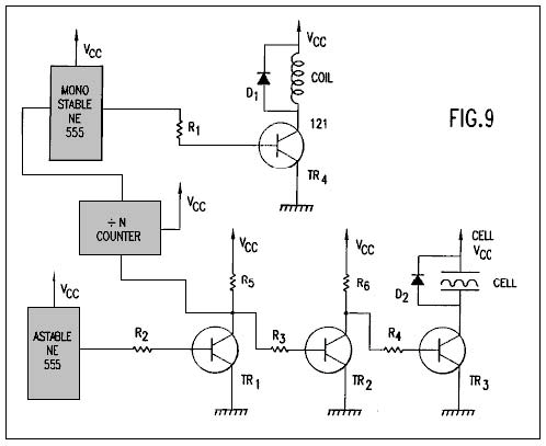
DETAILED
DESCRIPTION OF THE PREFERRED EMBODIMENT
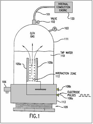
Fig.1
shows a first embodiment of the present invention including a cell for
producing hydrogen and oxygen. As will be discussed below in conjunction with Figs.6-8, the production of
parahydrogen requires an additional coil not shown in Fig.1. Thus, the hydrogen produced by the first embodiment of Fig.1 is orthohydrogen.
The
cell includes a closed container 111
which is closed at its bottom portion by threaded plastic base 113 and screw thread base 109. The container 111 can be made of, for example, Plexiglas and might have a height
of 430 mm and a width of 90 mm. The
container 111 holds tap water 110.
The
cell also includes a pressure gauge 103
to measure the pressure within the container 111. An outlet valve 102 is connected to the top of the
container 111 to permit any gas
within the container to escape into an output tube 101.
The
cell also includes an over-pressure valve 106
connected to a base 113. The valve 106 provides a safety function by automatically releasing the
pressure within the container 111 if
the pressure exceeds a predetermined threshold. For example, the valve 106 may be set so that it will open if the pressure in the
container exceeds 75 p.s.i. Since the
container 111 is built to withstand
a pressure of about 200 p.s.i., the cell is provided with a large safety
margin.
A
pair of electrodes 105a and 105b are arranged within the container 111.
These electrodes are submerged under the top level of the water 110 and define an interaction zone 112 between them. The electrodes are preferably made from the
same material, such as stainless steel.
In
order to produce an optimum amount of hydrogen and oxygen, an equal spacing
between the electrodes 105a and 105b must be maintained. Moreover, it is preferable to minimise the
spacing between the electrodes. However,
the electrodes cannot be positioned excessively close together, because arcing
between the electrodes would occur. It
has been determined that a spacing of 1 mm is the optimum spacing for producing
hydrogen and oxygen. Spacing up to 5 mm
can work effectively, but spacing above 5 mm has not worked well, except with
excessive power.
Hydrogen
and oxygen gas may be output through tube 101
to a device 120 which can use those
gases, for example an internal combustion engine, such as shown in Fig.1.
Instead of an internal combustion engine, device 120 may be any device using hydrogen and oxygen, including a
reciprocating piston engine, a gas turbine engine, a stove, a heater, a furnace,
a distillation unit, a water purification unit, a hydrogen/oxygen jet, or other
device using the gases. With an
adequately productive example of the present invention, any such device 120 using the output gases can be run
continuously without the need for storing dangerous hydrogen and oxygen gases.
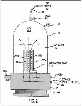
Fig.2
shows a second embodiment of the present invention which includes more than one
pair of electrodes 205a-d. The spacing between the electrodes is less
than 5 mm as in the embodiment of Fig.1.
While Fig.2 shows only one
additional pair of electrodes, it is possible to include many more pairs (e.g.,
as many as 40 pairs of electrodes) within the cell. The rest of the cell illustrated in Fig.2 remains the same as that
illustrated in Fig.1. The multiple electrodes are preferably flat
plates closely spaced, parallel to each other.
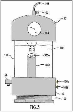
Fig.3 illustrates
a cell having a cylindrically shaped electrodes 305a and 305b. The outer electrode 305b surrounds the coaxially aligned inner electrode 305a.
The equal spacing of the electrodes 305a
and 305b is less than 5 mm and the
interactive zone is coaxially arranged between the two electrodes. While Fig.3
illustrates the top portion of the container 111 being formed by a plastic cap 301, it will be appreciated by those skilled in the art, that the
cap 301 may be used in the
embodiments of Fig.1 and Fig.2 and the embodiment of Fig.3 can utilise the same container 111 illustrated in Figs.1-2. As suggested by Fig.3,
the electrodes can be almost any shape such as flat plates, rods, tubes or
coaxial cylinders.
The
electrodes 105a and 105b of Fig.1 (or electrodes 205a-d
of Fig.2 or electrodes 305a and 305b of Fig.3) are
respectively connected to power supply terminals 108a and 108b so that
they can receive a pulsed electrical signal from a power supply. The pulsed signal can be almost any waveform
and have a variable current level, voltage level, frequency and mark-space
ratio (i.e., a ratio of the duration of a single pulse to the interval between
two successive pulses). For example, the
power supply providing power to the electrodes can be a mains 110 volts to a 12
volt supply or a car battery.
Fig.4a,
Fig.4b and Fig.4c illustrate a square wave, a saw tooth wave and a triangular
wave, respectively which can be applied to the electrodes 105a and 105b (or 205a-d or 305a, 305b) in
accordance with the present invention.
Each of the waveforms illustrated in Figs.4a-4c has a 1:1 mark-space ratio. As shown in Fig.4b, the saw tooth wave will only
reach a peak voltage at the end of the pulse duration. As shown in Fig.4c, the triangular wave has a low peak voltage. It has been found that optimal results for
producing hydrogen and oxygen in the present invention are obtained using a
square wave.
After
initiation of the pulsed signal from the power supply, the electrodes 105a and 105b continuously and almost instantaneously generate hydrogen and
oxygen bubbles from the water 110 in
the interaction zone 112. Moreover, the bubbles can be generated with
only minimal heating of the water or any other part of the cell. These bubbles rise through the water and
collect in the upper portion of the container 111.
The
generated bubbles are not bunched around or on the electrodes 105a and 105b and thus readily float to the surface of the water. Therefore, there is no need to add a chemical
catalyst to assist the conduction of the solution or reduce the bubble bunching
around or on the electrodes. Thus, only tap water is needed for generation of
the hydrogen and oxygen in the present invention.
The
gases produced within the container are self-pressurising (i.e., pressure
builds in the container by the production of gas, without an air pump). Thus,
no additional pump is needed to be coupled to the container 111 and the produced gases do no need
to be transported into a pressurised container.
The
power supply in the present invention is required to provide a pulsed signal
having only 12 volts at 300 mA (3.6 watts).
It has been found that an optimal amount of hydrogen and oxygen has been
produced when the pulsed signal has mark-space ratio of 10:1 and a frequency of
10-250 KHz. Using these parameters, the prototype cell of the present invention
is capable of producing gas at the rate of 1 p.s.i. per minute. Accordingly,
the cell of the present invention is capable of producing hydrogen and oxygen
in a highly efficient manner, quickly and with low power requirements.
As
noted above, the hydrogen produced by the embodiments of Figs.1-3 is orthohydrogen.
As is well understood by those skilled in the art, orthohydrogen is
highly combustible. Therefore, any
orthohydrogen produced can be transported from the container 111 through valve 102 and outlet tube 101
to be used by a device such as an internal combustion engine.
The
present invention, with sufficient electrodes, can generate hydrogen and oxygen
fast enough to feed the gases directly into an internal combustion engine or
turbine engine, and run the engine continuously without accumulation and
storage of the gases. Hence, this
provides for the first time a hydrogen/oxygen driven engine that is safe
because it requires no storage of hydrogen or oxygen gas.
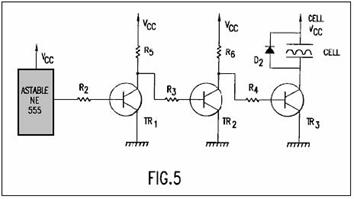
Fig.5
illustrates an exemplary power supply for providing D.C. pulsed signals such as
those illustrated in Figs.4a-4c to
the electrodes illustrated in Figs.1-3. As will be readily understood by those
skilled in the art, any other power supply which is capable of providing the
pulsed signals discussed above can be substituted.
The
power supply illustrated in Fig.5
includes the following parts, components and values:
The
astable circuit is connected to the base of transistor TR1 through resistor R2.
The collector of transistor TR1 is
connected to voltage supply Vcc
through resistor R5 and the base of
transistor TR2 through resistor R3.
The collector of transistor TR2
is connected to voltage supply Vcc
through resistor R6 and the base of
transistor TR3 through resistor R4.
The collector of transistor TR3
is connect to one of the electrodes of the cell and diode D2. The emitters of
transistors TR1, TR2 and TR3 are connected to ground. Resistors R5 and R6 serve as
collector loads for transistors TR1
and TR2, respectively. The cell serves as the collector load for
transistor TR3. Resistors R2, R3 and R4 ensure
that transistors TR1, TR2 and TR3 are saturated. Diode D2 protects the rest of the circuit
from any induced back emf within the cell.
The
astable circuit is used to generate a pulse train at a specific time and with a
specific mark-space ratio. This pulse train is provided to the base of
transistor TR1 through resistor R2.
Transistor TR1 operates as an
invert switch. Thus, when the a stable circuit produces an output pulse, the
base voltage of the transistor TR1
goes high (i.e. close to Vcc or
logic 1). Hence, the voltage level of the collector of transistor TR1 goes low (i.e., close to ground or
logic 0).
Transistor
TR2 also operates as an
inverter. When the collector voltage of
transistor TR1 goes low, the base
voltage of transistor TR2 also goes
low and transistor TR2 turns
off. Hence, the collector voltage of
transistor TR2 and the base voltage
of Transistor TR3 go high. Therefore, transistor TR3 turns on with the same mark-space ratio as the astable
circuit. When the transistor TR3 is on, one electrode of the cell is
connected to Vcc and the other is
connected to ground through transistor TR3.
Thus, the transistor TR3 can be
turned on (and off) and therefore the transistor TR3 effectively serves as a power switch for the electrodes of the
cell.
Figs.6-8
illustrate additional embodiments of the cell which are similar to the
embodiments of Figs.1-3,
respectively. However, each of embodiments of Figs.6-8 further includes a coil 104 arranged above the electrodes and power supply terminals 107 connected to the coil 104.
The dimensions of coil 104
can be, for example, 5 x 7 cm and have, for example, 1500 turns. The coil 104
is submerged under the surface of the water 110.
The
embodiments of Figs.6-8 further
include an optional switch 121 which
can be switched on or off by the user.
When the switch 121 is not
closed, then the cell forms basically the same structure as Figs.1-3 and thus can be operated in
the same manner described in Figs.1-3
to produce orthohydrogen and oxygen.
When the switch 121 is closed,
the additional coil 104 makes the
cell capable of producing oxygen and either (1) parahydrogen or (2) a mixture
of parahydrogen and orthohydrogen.
When
the switch 121 is closed (or not
included), the coil 104 is connected
through terminals 106 and the switch
121 (or directly connected only
through terminals 106) to a power
supply so that the coil 104 can a
receive a pulsed signal. As will be
discussed below, this power supply can be formed by the circuit illustrated in Fig.9.
When
the coil 104 and the electrodes 105a and 105b receive pulses, it is possible to produce bubbles of
parahydrogen or a mixture of parahydrogen and orthohydrogen. The bubbles are
formed and float to the surface of the water 110 as discussed in Figs.1-3. When the coil is pulsed with a higher
current, a greater amount of parahydrogen is produced. Moreover, by varying the voltage of the coil 104, a greater/lesser percentage of
orthohydrogen/parahydrogen can be produced. Thus, by controlling the voltage
level, current level and frequency (discussed below) provided to the coil 104 (and the parameters such as voltage
level, current level, frequency, mark-space ratio and waveform provided to the
electrodes 105a and 105b as discussed above) the
composition of the gas produced by the cell can be controlled. For example, it
is possible to produce only oxygen and orthohydrogen by simply disconnecting
the coil 104. It is also possible to produce only oxygen
and parahydrogen by providing the appropriate pulsed signals to the coil 104 and the electrodes 105a and 105b. All of the benefits
and results discussed in connection with the embodiments of Figs.1-3 are equally derived from the
embodiments of Figs.6-8. For example, the cells of Figs.6-8 are self-pressurising, require
no-chemical catalyst, do not greatly heat the water 110 or cell, and produce a large amount of hydrogen and oxygen
gases from a modest amount of input power, without bubbles on the electrodes.
A
considerable amount of time must pass before the next pulse provides current to
the coil 104. Hence, the frequency of the pulsed signal is
much lower than that provided to the electrodes 105a and 105b.
Accordingly, with the type of coil 104
having the dimensions described above, the frequency of pulsed signals can be
as high as 30 Hz, but is preferably 17-22 Hz to obtain optimum results.
Parahydrogen
is not as highly combustible as orthohydrogen and hence is a slower burning
form of hydrogen. Thus, if parahydrogen is produced by the cell, the
parahydrogen can be coupled to a suitable device such as a cooker or a furnace
to provide a source of power or heat with a slower flame.
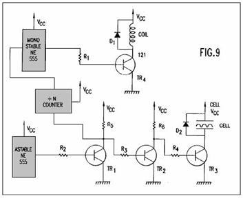
Fig.9
illustrates an exemplary power supply for providing D.C. pulsed signals such as
those illustrated in Figs.4a-4c to
the electrodes illustrated in Figs.6-8.
Additionally, the power supply can provide another pulsed signal to the
coil. As will be readily understood by
those skilled in the art, any other power supply which is capable of providing
the pulsed signals discussed above to the electrodes of the cell and the coil
can be substituted. Alternatively, the
pulsed signals provided to the electrodes and the coil can be provided by two
separate power supplies.
The
portion of the power supply (astable circuit, R2-R6, TR1-TR3, D2) providing a pulsed signal to the
electrodes of the cell is identical to that illustrated in Fig.5. The power supply illustrated in Fig.9 further includes the following parts and their respective
exemplary values:
The
input of the ‘divide-by-N’ counter (hereinafter "the divider") is
connected to the collector of transistor TR1. The output of the divider is connected to the
monostable circuit and the output of the monostable circuit is connected to the
base of transistor TR4 through
resistor R1. The collector of transistor TR4 is connected to one end of the coil
and a diode D1. The other end of the coil and the diode D1 are connected to the voltage supply Vcc.
Resistor R1 ensures that TR4 is fully saturated. Diode D2
prevents any induced back emf generated within the coil from damaging the rest
of the circuit. As illustrated in Figs.6-8, a switch 121 can also incorporated into the circuit to allow the user to
switch between (1) a cell which produces orthohydrogen and oxygen, and (2) a
cell which produces at least parahydrogen and oxygen.
The
high/low switching of the collector voltage of transistor TR1 provides a pulsed signal to the divider. The divider divides
this pulsed signal by N (where N is a positive integer) to produce a pulsed
output signal. This output signal is
used to trigger the monostable circuit.
The monostable circuit restores the pulse length so that it has a
suitable timing. The output signal from
the monostable circuit is connected to the base of transistor TR4 through resistor R1 to switch transistor TR4 on/off. When transistor TR4 is switched on, the coil is placed between Vcc and ground. When the
transistor TR4 is switched off, the
coil is disconnected from the rest of the circuit. As discussed in conjunction with Figs.6-8, the frequency of pulse signal
provided to the coil is switched at a rate preferably between 17-22 Hz; i.e.,
much lower than the frequency of the pulsed signal provided to the electrodes.
As
indicated above, it is not required that the circuit (divider, monostable circuit,
R1, TR4 and D1) providing the pulsed signal to the coil be connected to the
circuit (astable circuit, R2-R6, TR1-TR3, D2) providing the pulsed
signal to the electrodes. However,
connecting the circuits in this manner provides an easy way to initiate the
pulsed signal to the coil.
A
working prototype of the present invention has been successfully built and
operated with the exemplary and optimal parameters indicated above to generate
orthohydrogen, parahydrogen and oxygen from water. The output gas from the prototype has been
connected by a tube to the manifold inlet of a small one cylinder gasoline
engine, with the carburettor removed, and has thus successfully run such engine
without any gasoline:
CHARLES GARRETT
US Patent 2,006,676
2nd July 1935 Inventor: Charles H. Garrett
ELECTROLYTIC CARBURETTOR
Please
note that this is a re-worded excerpt from this patent. It describes an electrolyser which Charles
claimed was able to generate enough gas from hydrolysis of water, to be able to
run a car engine without the use of any other fuel. It should be remembered that in Garrett’s
day, car electrics were all 6-volt systems.
DESCRIPTION
This
invention relates to carburettors and it has particular reference to an
electrolytic carburettor by means of which water may be broken up into its
hydrogen and oxygen constituents and the gases so formed suitably mixed with
each other and with air.
Another
object of the invention is to provide a means whereby the electrolyte level in
the carburettor may be maintained at a more or less constant level regardless
of fluctuations in water pressure at the water inlet of the carburettor.
Another
object of the invention is to provide a means whereby the relative amount of air
mixed with the hydrogen and oxygen may be regulated as desired.
Still
another object of the invention is the provision of a means to prevent the loss
of hydrogen and oxygen gases during periods in which these gases are not being
drawn from the carburettor.
Still
another object of the invention is the provision of a means whereby the
hydrogen and oxygen resulting from electrolysis may be formed in separate
compartments, and a further object of the invention is the provision of a means
to periodically reverse the direction of current flow and thereby alternate the
evolution of the gases in the separate compartments, to be intermingled at a
later time.
With
reference to the accompanying drawings: -
Figure 1
is a view in vertical section of one form of carburettor.

Figure 2
is a modified form.
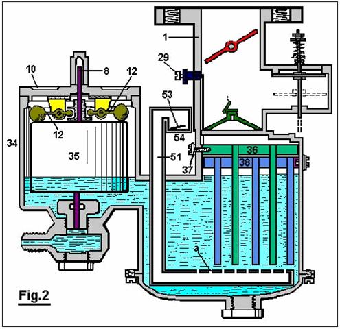
Figure 3
is a diagrammatic view of a pole changer, showing its actuating mechanism,
and

Figure 4
is a wiring diagram for the modified form of carburettor shown in Figure
2.
With
reference to Fig.1: The reference numeral 1 designates the carburettor housing, which is preferably
constructed of bakelite or other suitable insulating material. This housing is designed so as to divide the
carburettor into a float chamber 2
and gas generating chamber 4,
connected by a fluid passage 3.
Water
under pressure is forced into the carburettor through an opening 5 which communicates with the float
chamber 2 through the medium of the
sediment chamber 6 and the needle
valve orifice 7, which is closed by
a needle valve 8 when the device is
not in operation. A float 9 surrounds the needle valve 8 and is free to move vertically
relative thereto. Descending from the cover 10 to the float chamber 2
are two ears 11, located at spaced
intervals on opposite sides of the needle valve 8. The members 12 are
pivoted to the ears 11, as shown.
The weighted outer ends of the members 12
rest on top of the float 9, and
their inner ends are received in an annular groove in the collar 13 which is rigidly attached to the
needle valve 8.
Within
the gas generating chamber 4, a
series of spaced, descending plates 14
are suspended from a horizontal member 15
to which a wire 16 has electrical
contact through the medium of the bolt 17,
which extends inwards through housing 1
and is threaded into the horizontal member 15.
A second series of plates 18 is located between the plates 14 and attached to the horizontal
member 19, and has electrical
contact with the wire 20 through the
bolt 21.
A
gas passageway 22, in which a
butterfly valve 23 is located,
communicates with the gas generating chamber 4 through an orifice 24.
An air inlet chamber 25 has
communication with the gas passageway 22
above the orifice 24. A check valve 26 which opens downwards, controls the openings 27, and is held closed and inoperative
by means of light spring 28.
An
adjustable auxiliary air valve 29 is
provided in the wall of the gas passageway 22,
which air valve is closed by the butterfly valve 23 when the butterfly valve is closed, but communicates with the
outside air when the butterfly valve is open.
The
operation of the device is as follows :
The
chambers 2 and 4 are first filled to the level 'a' with a solution of weak sulphuric acid (or other electrolyte
not changed by the passage of current through it), and the opening 5 is connected to a tank of water (not
shown).
The
wire 16 is next connected to the
positive pole of a storage battery or other source of direct current and the
wire 20 to the negative pole. Since
the solution within the carburettor is a conductor of electricity, current will
flow through it and hydrogen will be given off from the negative or cathode
plates 18 and oxygen from the
positive or anode plates 14.
The
butterfly valve 23 is opened and the
gas passageway 22 brought into
communication with a partial vacuum.
Atmospheric pressure acting on the top of the check valve 26 causes it to be forced downwards as
shown in dotted lines. The hydrogen and oxygen liberated from the water at the
plates 18 and 14 are drawn upwards through the orifice 24 covered by the check valve 30
where they are mixed with air entering through the openings 27 and through the auxiliary air valve 29.
When
it is desired to reduce the flow of hydrogen and oxygen from the plates 18 and 14, the current flowing through the device is reduced, and when the
current is interrupted the flow ceases. When the butterfly valve 23 is moved to its ‘closed’ position,
the check-valve 26 is automatically
closed by the spring 28. Any excess given off during these operations
is stored in the space above the fluid where it is ready for subsequent use.
Water is converted into its gaseous
constituents by the device herein described, but the dilute sulphuric acid or
other suitable electrolyte in the carburettor remains unchanged, since it is
not destroyed by electrolysis, and the parts in contact therewith are made of
bakelite and lead or other material not attacked by the electrolyte.

The
structure shown in Fig.2 is
substantially the same as that shown in Fig.1
with the exception that the modified structure embraces a larger gas generating
chamber which is divided by means of an insulating plate 31 and is further provided with a depending baffle plate 32 which separates the gas generating
chamber 33 from the float chamber 34 in which the float 35 operates in the same manner as in Fig.1. Moreover, the structure shown in
Fig.2 provides a series of spaced
depending plates 36 which are
electrically connected to the wire 37,
and a second series of similar plates 38
which are electrically connected to the wire 39 and are kept apart from the plates 36 by the insulating plate 31.
Gases
generated on the surfaces of the plates 36
and 38 pass upward through the
orifice 39a into the gas passageway 40 where they are mixed with air as
explained in the description of Fig.1.
A
pipe 51, bent as shown in Fig.2, passes downwards through the
housing of the carburettor and has a series of spaced apertures 'a' in its horizontal portion beneath
the plates 36 and 38. Check valve 53, with opens upwards, controls air inlet 54. When a partial vacuum exists in the chamber 33, air is drawn in through the opening
54 and then passes upwards through
the apertures 'a'. This air tends to
remove any bubbles of gas collecting on the plates 36 and 38 and also tends
to cool the electrolyte. The check valve 53
automatically closes when a gas pressure exists within the carburettor and
thereby prevents the electrolyte from being forced out of the opening 54.
In
order to provide for alternate evolution of the gases from the plates 36 and 38, a pole changer 41,
shown in Fig.3, is actuated
periodically by the motor 42 which
drives the worm 43 and the gear 44 and causes oscillations of the
member 45 which is connected by a
spring 46 to the arm 47, thereby causing the pole changer to
snap from one position to the other.
In
operation, the carburettor shown in Fig.2
is connected as shown in the wiring diagram of Fig.4. A storage battery 48
or other suitable source of direct current is connected to a variable rheostat 49, switch 50, pole changer 41 and
to the carburettor as shown. Thus the rate of evolution of the gases can be
controlled by the setting of the rheostat 49
and the desired alternate evolution of the gases in the compartments of the
carburettor is accomplished by means of the periodically operated pole changer 41.
Manifestly,
the construction shown is capable of considerable modification and such
modification as is considered within the scope and meaning of the appended
claims is also considered within the spirit and intent of the invention.
ARCHIE BLUE
US Patent 4,124,463 7th November 1978 Inventor: Archie H. Blue
ELECTROLYTIC
CELL
Please note
that this is a re-worded excerpt from this patent. It describes an electrolyser system where air
is drawn through the electrolyte to dislodge bubbles from the electrodes.
ABSTRACT
In the electrolytic production of hydrogen and oxygen, air is pumped through the cell while the electrolysis is in progress so as to obtain a mixture of air, hydrogen and oxygen.
BACKGROUND AND BRIEF DESCRIPTION OF THE INVENTION
This invention relates to the production of gases which can be utilised primarily, but not necessarily, as a fuel.
To decompose water electrically, it is necessary to pass direct current between a pair of electrodes which are immersed in a suitable electrolyte. During such electrolysis, it is normal to place some form of gas barrier between the two electrodes, in order to prevent the gases produced forming an explosive mixture. However provided suitable precautions are taken, it has been found that the gases can be allowed to mix and can be fed into a storage tank for subsequent use. Because the gases when mixed form an explosive mixture, it is possible for the mixture to be utilised, for instance, as a fuel for an internal combustion engine. In such circumstances it is desirable that the gases should also be mixed with a certain proportion of air in order to control the explosive force which results when the gases are ignited.
One of the difficulties encountered with electrolysis is that bubbles of gas are liable to remain on the electrodes during the electrolysis thus effectively limiting the area of electrode which is in contact with the electrolyte and preventing optimum current flow between the electrodes. Because it is desirable that the gases evolved during the electrolysis be mixed with air, it is possible for air to be passed through the cell while electrolysis is in progress. The passage of air through the cell can be directed past the electrodes so as to pick up any gas bubbles on the electrodes.
Accordingly, the invention comprises an electrolytic cell with a gas tight casing, several electrodes supported on a central post within the cell, spaced apart and electrically insulated from each other, each alternative electrode being connected to a positive direct current source or a negative direct current source respectively and wherein the central post is in the form of a tube, one end of which is extended out of the cell and connected to a source of air under pressure, with the other end of the central post terminating in an air outlet below the electrodes. The cell also includes a gas outlet to carry the air forced into the cell through the central post and to exhaust the gases produced by electrolysis.
DETAILED DESCRIPTION OF THE INVENTION
Various forms of the invention will now be described with the aid of the accompanying drawings wherein:
Fig.1 is a diagrammatic elevational view partly in section of one form of the invention,
Fig.2 is a diagrammatic elevational view partly in section of a modified form of the invention,
Fig.3 is a section along the line III--III of Fig.2.
The cell as shown in Fig.1 comprises a gas-tight casing 10 which is formed from a material incapable of corrosion, such as plastic. Several cathode plates 11 and several anode plates 12 are supported within the cell on an electrically insulating central post 13, with the cathode plates and anode plates being spaced apart by means of insulating spacers 14. The anode plates 12 are all connected in parallel to a positive terminal post 15 while the cathode plates are all connected in parallel to the negative terminal post 16, these connections being indicated in dotted lines in the drawings. The cathode and anode plates are preferably in the form of discs made from a metal suited to the electrolyte, thus ensuring a satisfactory cell life. These plates may be shaped to conform with the shape of the walls of the cell which may be circular in cross section as indicated or any other desired shape.
The central post 26 is preferably in the form of a tube which extends out of the cell. The lower end of the tube 18 is open so that air can be pumped into the cell through the central post 26 and enter the cell via the lower end 18 where it will pass up through the electrolyte. This keeps the electrolyte in constant motion which assists in the rapid removal of any gas bubbles which may be adhering to the electrode plates.
In the modification shown in Fig.2 and Fig.3, each electrode plate is provided with holes 17. The central post 26 is also provided with at least one air hole 19 adjacent to its the lower end. A deflector plate 20 is also supported by the central post 26, this plate being dish shaped so as to deflect air issuing out of the air hole 19 up through the holes 17 in the electrodes. This further assists in dislodging any bubbles of gas clinging to the electrode plates.
The cell also includes a gas outlet 21 so that the air which enters the cell, together with the gases produced by electrolysis, can be taken out of the cell into a suitable storage tank (not shown in the drawings). If desired, such storage tank can be arranged to accept the gases under pressure and for this purpose the air pumped into the cell will be pumped in under the required pressure. A gas drier (not shown in the drawings) can also be interposed between the gas outlet 21 and the storage tank.
Although the electrolysis will naturally produce considerable heat, nevertheless it can be found advantageous to install a heater in the cell, preferably in the bottom of the cell, to assist and facilitate the warming up of the electrolyte so that the cell reaches its most efficient operating conditions as quickly as possible.
Preferably also, a current-control device should be employed so that the intensity of the electrolytic action can be controlled.
A mechanism may also be provided for the automatic replenishment of water within the cell as the level of the electrolytic drops during use.
While it is recognised that the mixing of hydrogen and oxygen will create a dangerous explosive mixture, nevertheless by carrying out the invention as described above, the risk of explosion is minimised. The gases produced can be utilised, for instance, as a fuel to power an internal combustion engine and for this purpose it is desirable, as already mentioned, to mix a proportion of air with the gases produced during electrolysis, so that when the mixture is ignited within the cylinder or cylinders of the engine, the explosive force so created can be of the desired amount.
While in the foregoing description reference is made to the utilisation of the mixed gases as a fuel, it will of course be understood that the gases can be separated for individual use.
Juan
Aguero’s Water-Fuel Engine
Patent Application EP0405919
1st February 1991 Inventor:
Juan C. Aguero
WATER-PROPELLED INTERNAL-COMBUSTION ENGINE SYSTEM
Please note
that this is a re-worded excerpt from this patent application. It describes a
method which it is claimed is capable of operating an internal combustion
engine from a mixture of steam and hydrogen gas.
ABSTRACT
This is an energy-transforming system for driving, for instance, an internal combustion engine which uses hydrogen gas as its fuel. The gas is obtained by electrolysing water on board and is then injected into the combustion chambers. The electrolysis is carried out in an electrolytic tank 15, energised with electric current generated by the engine. The hydrogen passes from a reservoir 23, via collector cylinder 29, to carburettor device 39. The hydrogen is then fed into the engine together with dry saturated steam and at least part of the hydrogen may be heated 51 prior to admission. A cooler and more controlled combustion is achieved with the steam and furthermore relatively lesser amounts of hydrogen are required. This is probably caused by the steam acting as a temperature moderator during admission and combustion of the hydrogen and additionally expanding during the expansion stroke.
FIELD OF THE INVENTION
The present invention refers to energy-converter systems, in particular related to an internal combustion engine fuelled by hydrogen gas, i.e. wherein the main propellant admitted to the combustion chambers is hydrogen. More particularly still, the present invention refers to method and means for obtaining hydrogen gas in an efficient and reasonably economical manner, and for supplying the gas to the combustion chambers under conditions for controlled ignition and optimum energy conversion. The present invention also refers to means and method for running an internal-combustion engine system from an available, cheap and non-contaminant hydrogen containing matter such as water as a fuel supply.
In general, the invention may find application in any system employing internal
combustion principles, ranging from large installations such as electricity
works to relatively smaller automobile systems like locomotives, lorries,
motor-cars, ships and motor-boats. In
the ensuing description, the invention is generally disclosed for application
in the automotive field, however its adaptation and application in other fields
may also be considered to be within the purview of the present invention.
BACKGROUND
Dwindling natural resources, dangerous contamination levels, increasing prices
and unreliable dependence on other countries are making it increasingly
necessary to search an alternative to fossil fuels like oil (hydrocarbons) and
oil derivatives as the primary energy source in automobiles. To date, none of the attempted alternatives
appears to have proved its worth as a substitute for petrol, either because of
inherent drawbacks as to contamination, safety, cost, etc. or because man has
not yet been able to find a practical way of applying the alternative energy
forms to domestic motor cars.
For instance, electricity is a good alternative in the ecological sense, both
chemically and acoustically, however it appears to be the least efficient form
of energy known, which together with the high cost of manufacture of electric
motors and the severe storage limitations insofar capacity and size have
stopped it from coming into the market at least for the time being. The same is generally true even when solar
energy is concerned.
Nuclear power is efficient, available and relatively cheap, but extremely
perilous. Synthetic fuels may certainly
be the answer in the future, however it appears that none practical enough have
been developed. Use of gases such as methane or propane, or of alcohol
distilled from sugar cane, has also been tried, but for one reason or another
its marketing has been limited to small regions. Methanol for instance is a promising synthetic
fuel, but it is extremely difficult to ignite in cold weather and has a low
energy content (about half that of petrol).
The use of hydrogen gas as a substitute for petrol has been experimented
lately. The chemistry investigator Derek P. Gregory is cited as believing that
hydrogen is the ideal fuel in not just one sense. Hydrogen combustion produces
steam as its only residue, a decisive advantage over contaminating conventional
fuels such as petrol and coal. Unfortunately,
hydrogen hardly exists on earth in its natural free form but only combined in
chemical compounds, from which it must be extracted using complicated,
expensive and often hazardous industrial processes. In addition, if this obstacle were overcome,
it would still be necessary to transport and store the hydrogen in service
stations and moreover find a safe and practical way of loading and storing it
in motor vehicles. Mercedes-Benz for one
is experimenting with a vehicle equipped with a special tank for storing
hydrogen gas and means for supplying the gas to the injection system, instead
of the conventional petrol tank and circuit, without however yet achieving a
satisfactory degree of safety and cost-efficiency. The use of dry hydrogen gas as a propellant
has heretofore been found to produce a generally uncontrolled ignition, a large
temperature excursion upwards which proved too destructive for the chamber
walls. The engine life was limited to
less than 10,000 km (about 6,000 miles).
DISCLOSURE OF THE INVENTION
The invention is based on the discovery of an energy-converter system to run an internal combustion engine and particularly is based on the discovery of a method and means for reliably, economically, safely and cleanly fuel an internal combustion engine with hydrogen, and obtaining the hydrogen in a usable form to this end from a cheap and plentifully available substance such as water. The hydrogen may be generated in optimum conditions to be fed into the engine.
According to the invention, hydrogen is obtained on board from a readily
available hydrogenous source such as ionised water which is subjected to
electrolysis, from whence the hydrogen is injected in each cylinder of the
engine on the admission stroke. The
hydrogen gas is mixed with water vapour (steam at atmospheric temperature) and
surrounding air, and when this mixture is ignited within the combustion
chamber, the steam (vapour) seems to act as a temperature moderator first and
then assist in the expansion stroke.
Preferably, the steam is dry saturated steam which, as a moderator,
limits the maximum temperature of the combustion, thus helping to preserve the
cylinder, valve and piston elements; and in assisting the expansion, the steam
expands fast to contribute extra pressure on the piston head, increasing the
mechanical output power of the engine.
In other words, the inclusion of steam in the hydrogen propellant as
suggested by the present invention moderates the negative effects of hydrogen
and enhances the positive effects thereof in the combustion cycle.
As a result of this discovery, the amount of hydrogen required to drive the
engine is lower than was heretofore expected, hence the electrolysis need not
produce more than 10 cc/sec (for example, for a 1,400 cc engine). Thus the
amount of electricity required for the electrolysis, a stumbling block in
earlier attempts, is lower, so much so, that on-board hydrogen production is
now feasible.
The invention includes an apparatus comprising a first system for generating
hydrogen and a second system for conditioning and supplying the hydrogen to the
admission valves on the cylinder caps. The hydrogen-generating system basically
consists of an electrolysis device which receives electrolitically adapted
(i.e. at least partially ionised) water or some other suitable hydrogenous
substance. An electric power supply is
connected to the electrodes of the electrolysis device for generating the
hydrogen, and the electricity requirements and the device dimensions are
designed for a maximum hydrogen output rate of about 10 cc/sec for a typical
automotive application.
The second system comprises means such as a vacuum pump or the like to draw out
the hydrogen from the first system, means for supplying the hydrogen gas to the
admission valves, means for conditioning the moisture content of the hydrogen,
carburettor means or the like for mixing the hydrogen with atmospheric air or
some other combustion enabling substance, and means to control and maintain a
specified gas pressure valve or range for the hydrogen supplied to the mixing
means.
The apparatus was tested and worked surprisingly well. It was discovered that
this seemed to be the result of the steam content in the electrolytic hydrogen
gas overcoming the pitfalls encountered in the prior art systems which injected
relatively dry gas into the cylinder chambers, or at the most with a relatively
small proportion of humidity coming from the air itself.
In the preferred embodiment, the electrolysis system is driven with a pulsed DC
power signal of up to 80 Amps at between 75 and 100 Volts. The electrolyte is distilled water salted
with sodium chloride with a concentration of about 30 grams of salt per litre
of water, to 150 grams of salt in 10 litres of water. Other concentrations are possible depending
on the kind of engine, fuel and electricity consumption etc. The maximum rate
of hydrogen production required for a typical domestic car engine has been
estimated at 10 cc/sec. This hydrogen is
drawn out by a pump generating a pressure head of around 2 Kg/cm2 to
feed the generated steam-containing hydrogen to a receptacle provided with
means for removing the undesired excess of moisture from the gas. The gas is thus mixed with the desired
content of steam when it enters the carburettor or mixing device.
In the event that the generated hydrogen does not have enough steam content,
dry saturated steam may be added to the hydrogen as it proceeds to the
engine. This may done conveniently,
before it enters the carburettor and is mixed with the intake air. Part of the gas may be shunted via a
heat-exchanger serpentine connected to the exhaust manifold. This heats some of the gas before it is
injected into the base of the carburettor.
This heated gas injection operates like a supercharger. The main unheated hydrogen stream is piped directly
into the venturi system of the carburettor, where it mixes with air drawn in by
the admission stroke vacuum.
BRIEF DESCRIPTION OF THE DRAWINGS
Fig.1 is a schematic layout of the first and second systems and shows the electrolysis device for obtaining hydrogen, and the circuit means for injecting the steam-laden hydrogen into the combustion chambers of a car engine, according to one embodiment of this invention.
Figure 2 is an elevational view of the electrolysis device of figure 1.
DETAILED
ACCOUNT OF AN EMBODIMENT
Fig.1 shows a system 11 for obtaining hydrogen front water piped from a reservoir or tank (not illustrated) to an inlet 13 of an electrolysis cell 15. The water is salted by adding sodium chloride to ionise it and enable electrolysis when electric power is applied to a pair of terminals 17. As disclosed in more detail later, the power applied to the terminals 17 is in the form of a DC pulse signal of 65 Amps at 87 Volts, generated via a suitable converter from, in the event that the present system is applied to an automobile, the standard automotive 12 Volt DC level. The device 15 has various outlets, one of which is the hydrogen gas outlet 19 which is connected through a solenoid valve 21 to an accumulator or reservoir cylinder 23. Other outlets of the electrolysis device 15 are for removing electrolysis effluents such as sodium hydroxide and chlorine gas, to which further reference is made below.
A vacuum pump 25 or similar,
extracts gas from the reservoir 23
and channels it through a hydrogen circuit system 27. Thus the reservoir 23 acts as a pressure buffer of a
systems interface between the electrolysis device 15 and the pump 25. The reservoir 23 may be a 2,000 cc capacity, stainless-steel cylinder with the
valve 21 metering the passage of gas
through it, so that the reservoir is initially filled with about 1,500 cc of
hydrogen at normal pressure and temperature (NPT) conditions. To this end, the
cylinder 23 may be provided with a
gauge 28V which controls the state
of valve 21 electronically. Valve 21
may be a Jefferson Model SPS solenoid valve, available from OTASI,
Pump 25 sends hydrogen through
tubing 26, which also includes a
by-pass 24 provided for inspection
and safety purposes together with a two-way valve 28, and into a second cylinder 29
which contains means 31 which cause
a turbulence or a labyrinthine movement in the gas, in order to condense the
heavy mixture, schematically shown as droplets 32, present in the gas stream. The condensed mixture collects in
the form of distilled water 33 at
the bottom of cylinder 29. Near the top of the cylinder, there is an
outlet 35 through which hydrogen
gas, laden with a good amount of steam, is transported to mixer 37.
Also at the top of collector cylinder 29, there is a temperature sensor 38 which is connected to an electronic digital thermometer circuit
(not shown).
Mixer 37 comprises a carburettor
device 39 for mixing hydrogen with
air prior to feeding the mixture to the combustion chambers. The hydrogen is piped through a 3/8"
diameter tube 41 from dryer cylinder
29 and then into the venturi section
43 of the carburettor 39 through a pair of 5/16"
diameter tubes or hydrogen injecting nozzles 45. The venturi section 43
is a section of the intake air passage which narrows to increase the air speed
at the point where hydrogen is drawn out for mixing. The venturi intake 42 may be covered by a mesh 46. However, it appears that no air filter is
needed for the mixer to operate well. The carburettor device 39 may be a simplified form of a
conventional carburettor, since the propellant, i.e. hydrogen gas, is fed
directly to the venturi 43. A butterfly valve, or the like, connected to
an accelerator pedal (not illustrated) of the motor-car, controls the air
intake rate and therefore the speed of the engine. This mixer device 39 is mounted as is a conventional
carburettor, such that its outlet at the bottom communicates with the admission
valves in the cylinder caps.
At the bottom part of the carburettor there is a supplementary hydrogen intake 47 connected to another 3/8"
diameter pipe 49 which shunts part
of the hydrogen through a heater 51. This heater comprises a serpentine tube 51 of a chromium/cobalt alloy, mounted
in close heat-exchange relationship with the body of the exhaust manifold 50 (schematically illustrated) in order
to add a portion of heated gas to the fuel mixture before it is drawn into the
combustion chambers through the corresponding admission valves on the cylinder
caps. This pre-admission heating step,
takes the hydrogen mixture to a near critical temperature for detonation. It
has been found that this improves performance (e.g. the engine smoothness) at
some speed ranges, and it works like a supercharger.
In practice, the engine of the present invention has shown a high efficiency
when using three-electrode sparking plugs and an electronic ignition system
(not illustrated).
Fig.2 shows the electrolysis cell 15 outlined in Fig.1 in more detail. It is
comprised of a rectangular prism reservoir 53
with a pair of spaced-apart vertical electrodes 55. The reservoir may
measure, for instance, 24 cm long by 20 cm wide and 28 cm high. Both the anode and cathode 55 may each comprise double electrodes
of carbon having a spacing between the electrodes 55 of the same polarity of about 10 cm. Alternatively, the anode 55A may be a ring made of carbon while
the cathode 55C is an iron-mesh
cylindrical electrode. Each electrode 55 has a terminal 57 at the top for inputting electric power as mentioned
earlier. At each outer side of the
electrodes 55 there is a porous
membrane 59 made from a sheet of
amianto (asbestos) for holding the water solution 61 in whilst at the same time letting the electrolysis products,
i.e. hydrogen and oxygen, pass through.
Thus, the hydrogen gas passes through the membrane 59 into a gas collector chamber 56 and exits out through pipe 19
to fuel the combustion engine. The
hydrogen pipe 19 may have a
proportioning valve 62 for
regulating the flow of hydrogen. The
oxygen on the other hand may be vented out into the atmosphere through an
outlet 63.
There is a heater element 64,
immersed in the salted water 61 fed
through a resistor connected to a 12
The electrolysis of the heated salted water solution 61 further produces, as effluents, chlorine gas (Cl2)
and sodium hydroxide (NaOH). The
chlorine gas may be vented through an opening 65 at the top of the reservoir 53
or else stored in an appropriate disposal tank (not shown). The sodium hydroxide precipitates and may be
removed periodically through tap 67
at the bottom of the electrolysis cell.
It is important to note that the practice of the present invention requires
practically no modifications in the engine itself. That is, existing petrol engines may be used
with hardly any adjustments. Ignition is
initiated at the dead top of the compression stroke or with a 1.5 degree lag at
the most, and it has been found convenient to widen the gaps of the admission
and exhaust valve pushers and use tri-electrode spark plugs. However it is advisable to use some
rust-resistant compound such as plastics for the exhaust pipe and silencer,
bearing in mind that the combustion residue is hot steam.
Fig.1 also shows schematically, the
electric power supply 71 connected
to the terminals 17 of the cube 15.
Electrical current is obtained at 12 volt DC from the car
battery/alternator system 73 and
processed by an inverter device 75
for generating DC pulses of 65 Amps at 87 Volts. Pulse energisation of the
electrolysis appears to maximise the ratio of hydrogen output rate to electric
power input.
The HHO
Fuel System of Stephen Horvath
US Patent 3,980,053 14th
September 1976 Inventor: Stephen
Horvath
FUEL SUPPLY APPARATUS FOR INTERNAL COMBUSTION ENGINES
Please note
that this is a re-worded excerpt from this patent. It describes the water-splitting procedure of
Stephen Horvath.
ABSTRACT
A fuel supply apparatus generates hydrogen and oxygen by electrolysis of water. There is provided an electrolytic cell which has a circular anode surrounded by a cathode with a porous membrane between them. The anode is fluted and the cathode is slotted to provide anode and cathode areas of substantially equal surface area. A pulsed electrical current is provided between the anode and cathode for the efficient generation of hydrogen and oxygen.
The electrolytic cell is equipped with a float, which detects the level of electrolyte within the cell, and water is added to the cell as needed to replace the water lost through the electrolysis process. The hydrogen and oxygen are collected in chambers which are an integral part of the electrolytic cell, and these two gases are supplied to a mixing chamber where they are mixed in the ratio of two parts hydrogen to one part oxygen. This mixture of hydrogen and oxygen flows to another mixing chamber wherein it is mixed with air from the atmosphere.
The system is disclosed as being installed in an car, and a dual control system, which is actuated by the car throttle, first meters the hydrogen and oxygen mixture into the chamber wherein it is combined with air and then meters the combined mixture into the car engine. The heat of combustion of a pure hydrogen and oxygen mixture is greater than that of a gasoline and air mixture of comparable volume, and air is therefore mixed with the hydrogen and oxygen to produce a composite mixture which has a heat of combustion approximating that of a normal gas-air mixture. This composite mixture of air, hydrogen and oxygen then can be supplied directly to a conventional internal combustion engine without overheating and without creation of a vacuum in the system.
BACKGROUND
OF THE INVENTION
This invention relates to internal combustion engines. More particularly it is concerned with a fuel supply apparatus by means of which an internal combustion engine can be run on a fuel comprised of hydrogen and oxygen gases generated on demand by electrolysis of water.
In electrolysis a potential difference is applied between an anode and a
cathode in contact with an electrolytic conductor to produce an electric
current through the electrolytic conductor. Many molten salts and hydroxides
are electrolytic conductors but usually the conductor is a solution of a
substance which dissociates in the solution to form ions. The term
"electrolyte" will be used herein to refer to a substance which
dissociates into ions, at least to some extent, when dissolved in a suitable
solvent. The resulting solution will be referred to as an "electrolyte
solution".
Faraday's Laws of Electrolysis provide that in any electrolysis process the
mass of substance liberated at an anode or cathode is in accordance with the
formula
m = z q
where m is the mass of substance liberated in grams, z is the electrochemical
equivalent of the substance, and q is the quantity of electricity passed, in
coulombs. An important consequence of Faraday's Laws is that the rate of
decomposition of an electrolyte is dependent on current and is independent of
voltage. For example, in a conventional electrolysis process in which a
constant current I amps flows to t seconds, q = It and the mass of material
deposited or dissolved will depend on I regardless of voltage, provided that
the voltage exceeds the minimum necessary for the electrolysis to proceed. For
most electrolytes, the minimum voltage is very low.
There have been previous proposals to run internal combustion engines on a fuel
comprised of hydrogen gas. Examples of such proposals are disclosed in U.S.
Pat. Nos. 1,275,481, 2,183,674 and 3,471,274 and British specifications Nos.,
353,570 and 364,179. It has further been proposed to derive the hydrogen from
electrolysis of water, as exemplified by U.S. Pat. No. 1,380,183. However, none
of the prior art constructions is capable of producing hydrogen at a rate such
that it can be fed directly to internal combustion engines without intermediate
storage. The present invention enables a fuel comprised of hydrogen and oxygen
gases to be generated by electrolysis of water at such a rate that it can
sustain operation of an internal combustion engine. It achieves this result by
use of an improved electrolysis process of the type generally proposed in the
parent application hereof.
As disclosed in my aforesaid parent application the prior art also shows
electrolytic reactions employing DC or rectified AC which necessarily will have
a ripple component; an example of the former being shown for instance in Kilgus
U.S. Pat. No. 2,016,442 and an example of the latter being shown in Emich al.
U.S. Pat. No. 3,485,742. It will be noted that the Kilgus Patent also discloses
the application of a magnetic field to his electrolyte, which field is said to
increase the production of gas at the two electrodes.
SUMMARY OF THE INVENTION
The apparatus of the invention applies a pulsating current to an electrolytic solution of an electrolyte in water. Specifically, it enables high pulses of quite high current value and appropriately low voltage to be generated in the electrolyte solution by a direct input supply to produce a yield of electrolysis products such that these products may be fed directly to the internal combustion engine. The pulsating current generated by the apparatus of the present invention is to be distinguished from normal variations which occur in rectification of AC current and as hereinafter employed the term pulsed current will be taken to mean current having a duty cycle of less than 0.5.
It is a specific object of this invention to provide a fuel supply apparatus
for an internal combustion engine by which hydrogen and oxygen gases generated
by electrolysis of water are mixed together and fed directly to the internal
combustion engine.
A still further object of the invention is to provide, for use with an internal
combustion engine having inlet means to receive a combustible fuel, fuel supply
apparatus comprising:
a vessel to hold an electrolyte solution of electrolyte dissolved in water;
an anode and a cathode to contact the electrolyte solution within the vessel;
electrical supply means to apply between said diode and said cathode pulses of
electrical energy to induce a pulsating current in the electrolyte solution
thereby to generate by electrolysis hydrogen gas at the cathode and oxygen gas
at the anode;
gas collection and delivery means to collect the hydrogen and oxygen gases and
to direct them to the engine inlet means; and
water admission means for admission of water to said vessel to make up loss due
to electrolysis.
In order that the invention may be more fully explained one particular example
of an car internal combustion engine fitted with fuel supply apparatus in
accordance with the invention will now be described in detail with reference to
the accompanying drawings.
BRIEF DESCRIPTION OF THE DRAWINGS
Fig.1 is a plan view of part of the car with its engine bay exposed to show the layout of the fuel supply apparatus and the manner in which it is connected to the car engine;

Fig.2 is a circuit diagram of the
fuel supply apparatus;
Fig.3 is a plan view of a housing
which carries electrical components of the fuel supply apparatus;
Fig.4 is an elevation view of the
housing shown in Fig.3;
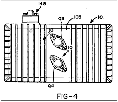
Fig.5 is a cross-section on the line
5--5 in Fig.3;
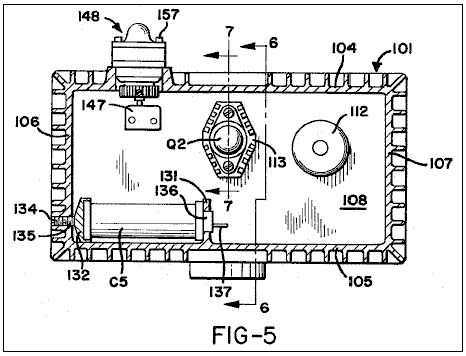
Fig.6 is a cross-section on the line
6--6 in Fig.3;
Fig.7 is a cross-section on the line
7--7 in Fig.5;
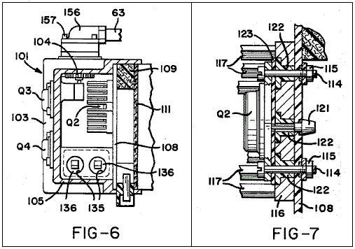
Fig.8 is a perspective view of a
diode heat sink included in the components illustrated in Fig.5 and Fig.7;
Fig.9 illustrates a transformer coil
assembly included in the electrical components mounted within the housing;

Fig.10 is a cross-section on the
line 10--10 in Fig.4;
Fig.11 is a cross-section on the
line 11--11 in Fig.5;
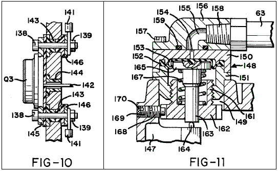
Fig.12 is a cross-section through a
terminal block mounted in the floor of the housing;
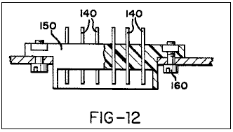
Fig.13 is a plan view of an
electrolytic cell incorporated in the fuel supply apparatus;
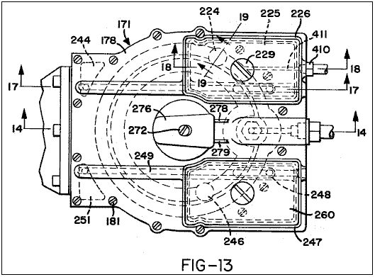
Fig.14 is a cross-section on the
line 14--14 in Fig.13;
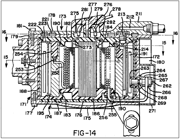
Fig.15 is a cross-section generally
on the line 15--15 in Fig.14;
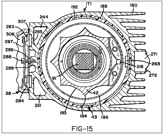
Fig.16 is a cross-section on the
line 16--16 in Fig.14;
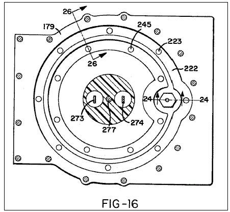
Fig.17 is a cross-section on the
line 17--17 in Fig.13;
Fig.18 is a cross-section on the
line 18--18 of Fig.13;
Fig.19 is a vertical cross-section through a gas valve taken generally on line 19--19 in Fig.13;
Fig.20 is a perspective view of a
membrane assembly disposed in the electrolytic cell;
Fig.21 is a cross-section through
part of the membrane assembly;
Fig.22 is a perspective view of a
float disposed in the electrolytic cell;
Fig.23 is an enlargement of part of
Fig.14;
Fig.24 is an enlarged cross-section
on the line 24--24 in Fig.16;
Fig.25 is a perspective view of a
water inlet valve member included in the components shown in Fig.24;
Fig.26 is a cross-section on line
26--26 in Fig.16;
Fig.27 is an exploded and partly
broken view of a cathode and cathode collar fitted to the upper end of the
cathode;
Fig.28 is an enlarged cross-section
showing some of the components of Fig.15;

Fig.29 is a perspective view of a
valve cover member;
Fig.30 shows a gas mixing and
delivery unit of the apparatus generally in side elevation but with an air
filter assembly included in the unit shown in section;
Fig.31 is a vertical cross-section
through the gas mixing and delivery unit with the air filter assembly removed;
Fig.32 is a cross-section on the
line 32--32 in Fig.31;
Fig.33 is a perspective view of a
valve and jet nozzle assembly incorporated in the gas mixing and delivery unit;
Fig.34 is a cross-section generally
on the line 34--34 in Fig.31;
Fig.35 is a cross-section through a
solenoid assembly;
Fig.36 is a cross-section on the
line 36--36 in Fig.32;
Fig.37 is a rear elevation of part
of the gas mixing and delivery unit;
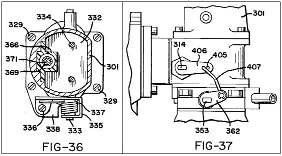
Fig.38 is a cross-section on the
line 38--38 in Fig.34;
Fig.39 is a plan view of the lower
section of the gas mixing and delivery unit, which is broken away from the
upper section along the interface 39--39 of Fig.30;
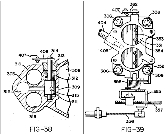
Fig.40 is a cross-section on the
line 40--40 in Fig.32; and
Fig.41 is a plan of a lower body
part of the gas mixing and delivery unit.
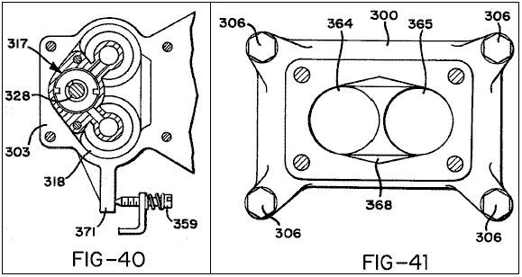
DESCRIPTION OF THE PREFERRED EMBODIMENT
Fig.1 shows an assembly denoted generally as 31 having an engine bay 32 in which an internal combustion engine 33 is mounted behind a radiator 34. Engine 33 is a conventional engine and, as illustrated, it may have two banks of cylinders in "V" formation. Specifically, it may be a V8 engine. It is generally of conventional construction and Fig.1 shows the usual cooling fan 34, fan belt 36 and generator or alternator 37.
In accordance with the invention the engine does not run on the usual petroleum
fuel but is equipped with fuel supply apparatus which supplies it with a
mixture of hydrogen and oxygen gases generated as products of a water
electrolysis process carried out in the fuel supply apparatus. The major
components of the fuel supply apparatus are an electrolytic cell denoted
generally as 41 and a gas mixing and
delivery unit 38 to mix the hydrogen
and oxygen gases generated within the cell 41
and to deliver them to engine 33. The electrolytic cell 41 receives water through a water delivery line 39 to make up the electrolyte solution
within it. It has an anode and a
cathode which contact the electrolyte solution, and in operation of the
apparatus pulses of electrical energy are applied between the anode and cathode
to produce pulses of high current flow through the electrolyte solution. Some of the electrical components necessary
to produce the pulses of electrical energy applied between the anode and
cathode are carried in a housing 40
mounted on one side of engine bay 32. The car battery 30 is mounted at the other side of the engine bay.
Before the physical construction of the fuel delivery apparatus is described in
detail the general principles of its operation will firstly be described with
reference to the electrical circuit diagram of Fig.2.
In the illustrated circuit terminals 44,
45, 46 are all connected to the positive terminal of the car battery 30 and terminal 47 is connected to the negative terminal of that battery. Switch 48
is the usual ignition switch of the car and closure of this switch provides
current to the coil 49 of a relay 51.
The moving contact 52 of
relay 51 receives current at 12
volts from terminal 45, and when the
relay is operated by closure of ignition switch 48 current is supplied through this contact to line 53 so that line 53 may be considered as receiving a positive input and line 54 from terminal 47 may be considered as a common negative for the circuit. Closure
of ignition switch 48 also supplies
current to one side of the coil 55
of a solenoid 56. The other side of
solenoid coil 55 is earthed by a
connection to the car body within the engine bay. As will be explained below solenoid 56 must be energised to open a valve
which controls supply of hydrogen and oxygen gases to the engine and the valve
closes to cut off that supply as soon as ignition switch 48 is opened.
The function of relay 51 is to
connect circuit line 53 directly to
the positive terminal of the car battery so that it receives a positive signal
directly rather than through the ignition switch and wiring.
The circuit comprises pulse generator circuitry which includes unijunction
transistor Q1 with associated
resistors R1, R2 and R3 and
capacitors C2 and C3. This circuitry produces pulses
which are used to trigger an NPN silicon power transistor Q2 which in turn provides via a capacitor C4 triggering pulses for a thyristor T1.
Resistor R1 and capacitor C2 are connected in series in a line 57 extending to one of the fixed
contacts of a relay 58. The coil 59
of relay 58 is connected between
line 53 and a line 61 which extends from the moving
contact of the relay to the common negative line 54 via a normally closed pressure operated switch 62.
The pressure control line 63
of switch 62 is connected in a
manner to be described below to a gas collection chamber of electrolytic cell 41 in order to provide a control
connection whereby switch 62 is
opened when the gas in the collection chamber reaches a certain pressure. However, provided that switch 62 remains closed, relay 58 will operate when ignition switch 48 is closed to provide a connection
between lines 57 and 61 thereby to connect capacitor C2 to the common negative line 54. The main purpose of relay 58 is to provide a slight delay in this
connection between the capacitor C2
and the common negative line 54 when
the circuit is first energised. This
will delay the generation of triggering pulses to thyristor T1 until a required electrical
condition has been achieved in the transformer circuitry to be described
below. Relay 58 is hermetically sealed and has a balanced armature so that it
can operate in any position and can withstand substantial shock or vibration
when the car is in use.
When the connection between capacitor C2
and line 54 is made via relay 58, unijunction transistor Q1 will act as an oscillator to provide
positive output pulses in line 64 at
a pulse rate which is controlled by the ratio of R1:C1 and at a pulse strength determined by the ratio of R2:R3.
These pulses will charge the capacitor C3. Electrolytic capacitor C1 is connected directly between the
common positive line 53 and the
common negative line 54 to filter
the circuitry from all static noise.
Resistor R1 and capacitor C2 are chosen such that at the input to
transistor Q1 the pulses will be of
saw tooth form. This will control the form of the pulses generated in the
subsequent circuitry and the saw tooth pulse form is chosen since it is
believed that it produces the most satisfactory operation of the pulsing
circuitry. It should be stressed,
however, that other pulse forms, such as square wave pulses, could be
used. Capacitor C3 discharges through a resistor R4 to provide triggering signals for transistor Q2. Resistor R4 is connected to the common negative line 54 to serve as a gate current limiting device for transistor Q2.
The triggering signals produced by transistor Q2 via the network of capacitor C3 and a resistor R4
will be in the form of positive pulses of sharply spiked form. The collector of
transistor Q2 is connected to the
positive supply line 53 through
resistor R6 while the emitter of
that transistor is connected to the common negative line 54 through resistor R5.
These resistors R5 and R6 control the strength of current
pulses applied to a capacitor C4,
which discharges through a resistor R7
to the common negative line 54,
thereby to apply triggering signals to the gate of thyristor T1.
The gate of thyristor T1
receives a negative bias from the common negative line via resistor R7 which thus serves to prevent
triggering of the thyristor by inrush currents.
The triggering pulses applied to the gate of thyristor T1 will be very sharp spikes occurring at the same frequency as the
saw tooth wave form pulses established by unijunction transistor Q1.
It is preferred that this frequency be of the order of 10,000 pulses per
minute and details of specific circuit components which will achieve this
result are listed below. Transistor Q2
serves as an interface between unijunction transistor Q1 and thyristor T1,
preventing back flow of emf from the gate of the thyristor which might
otherwise interfere with the operation of transistor Q1. Because of the high
voltages being handled by the thyristor and the high back emf applied to
transistor Q2, the latter transistor
must be mounted on a heat sink.
The cathode of thyristor T1 is
connected via a line 65 to the
common negative line 54 and the
anode is connected via a line 66 to
the centre of the secondary coil 67
of a first stage transformer TR1.
The two ends of transformer coil 67
are connected via diodes D1 and D2 and a line 68 to the common negative line 54
to provide full wave rectification of the transformer output.
First stage transformer T1 has three
primary coils 71, 72, 73 wound
together with secondary coil 67
about a core 74. This transformer
may be of conventional half cup construction with a ferrite core. The secondary
coil may be wound on to a coil former disposed about the core and primary coils
71 and 73 may be wound in bifilar fashion over the secondary coil. The other primary coil 72 may then be wound over the coils 71, 73. Primary coils 71 and 73 are connected at one side by a line 75 to the uniform positive potential of circuit line 53 and at their other sides by lines 79, 81 to the collectors of transistors
Q3, Q4. The emitters of
transistors Q3, Q4 are connected
permanently via a line 82 to the
common negative line 54. A capacitor C6 is connected between lines 79,
81 to act as a filter preventing any potential difference between the
collectors of transistors Q3, Q4.
The two ends of primary coil 72 are
connected by lines 83, 84 to the
bases of transistors Q3, Q4. This
coil is centre tapped by a line 85
connected via resistor R9 to the
positive line 53 and via resistor R10 to the common negative line 54.
When power is first applied to the circuit transistors Q3 and Q4 will be in their
non-conducting states and there will be no current in primary coils 71, 73.
However, the positive current in line 53 will provide via resistor R9
a triggering signal applied to the centre tap of coil 72 and this signal operates to trigger alternate high frequency
oscillation of transistors Q3, Q4
which will result in rapid alternating pulses in primary coils 71, 73.
The triggering signal applied to the centre tap of coil 72 is controlled by the resistor
network provided by resistors R9 and
R10 such that its magnitude is not
sufficient to enable it to trigger Q3
and Q4 simultaneously but is
sufficient to trigger one of those transistors. Therefore only one of the
transistors is fired by the initial triggering signal to cause a current to
flow through the respective primary coil 71
or 73. The signal required to hold
the transistor in the conducting state is much less than that required to
trigger it initially, so that when the transistor becomes conductive some of
the signal applied to the centre tap of coil 72 will be diverted to the non-conducting transistor to trigger
it. When the second transistor is thus
fired to become conductive, current will flow through the other of the primary
coils 71, 73, and since the emitters
of the two transistors are directly connected together, the positive output of
the second transistor will cause the first-fired transistor to be shut off.
When the current drawn by the collector of the second-fired resistor drops,
part of the signal on the centre tap of coil 72 is diverted back to the collector of the first transistor which
is re-fired. It will be seen that the cycle will then repeat indefinitely so
that transistors Q3, Q4 are
alternately fired and shut off in very rapid sequence. Thus current pulses flow
in alternate sequence through primary coils 71, 73 at a very high frequency, this frequency being constant and
independent of changes in input voltage to the circuit. The rapidly alternating
pulses in primary coils 71 and 73, which will continue for so long as
ignition switch 48 remains closed,
will generate higher voltage signals at the same frequency in the transformer
secondary coil 67.
A dump capacitor C5 bridged by a
resistor R8 is connected by a line 86 to the line 66 from the secondary coil of transformer TR1 and provides the output from that transformer which is fed via
line 87 to a second stage
transformer TR2.
When thyristor T1 is triggered to
become conductive the full charge of dump capacitor C5 is released to second stage transformer TR2. At the same time the
first stage of transformer TR1
ceases to function because of this momentary short circuit placed across it and
consequently thyristor T1 releases,
i.e. becomes non-conductive. This
permits charge to be built up again in dump capacitor C5 for release when the thyristor is next triggered by a signal
from transistor Q2. Thus during each of the intervals when the
thyristor is in its non-conducting state the rapidly alternating pulses in
primary coils 71, 73 of transformer TR1 produced by the continuously oscillating
transistors Q3, Q4 produce, via the
transformer coupling, relatively high voltage output pulses which build up a
high charge in capacitor C5, and
this charge is released suddenly when the thyristor is triggered. In a typical
apparatus using a 12 volt DC supply battery pulses of the order of 22 amps at
300 volts may be produced in line 87.
As previously mentioned relay 58 is
provided in the circuit to provide a delay in the connection of capacitor C2 to the common negative line 54.
This delay, although very short, is sufficient to enable transistors Q3, Q4 to start oscillating to cause transformer TR1 to build up a charge in dumping capacitor C5 before the first triggering signal is applied to thyristor T1 to cause discharge of the capacitor.
Transformer TR2 is a step-down
transformer which produces pulses of very high current flow at low voltage. It
is built into the anode of electrolytic cell 41 and comprises a primary coil 88 and a secondary coil 89
wound about a core 91. Secondary
coil 89 is formed of heavy wire in
order to handle the large current induced in it and its ends are connected
directly to the anode 42 and cathode
43 of the electrolytic cell 41 in a manner to be described below.
In a typical apparatus, the output from the first stage transformer TR1 would be 300 volt pulses of the
order of 22 amps at 10,000 pulses per minute and a duty cycle of slightly less
than 0.006. This can be achieved from a uniform 12 volt and 40 amps DC supply
using the following circuit components:
Components:
R1 2.7 k ohms 1/2 watt 2% resistor
R2 220 ohms 1/2 watt 2% resistor
R3 100 ohms 1/2 watt 2% resistor
R4 22 k ohms 1/2 watt 2% resistor
R5 100 ohms 1/2 watt 2% resistor
R6 220 ohms 1/2 watt 2% resistor
R7 1 k ohms 1/2 watt 2% resistor
R8 10 m ohms 1 watt 5% resistor
R9 100 ohms 5 watt 10% resistor
R10 5.6 ohms 1 watt 5% resistor
C1 2200 mF 16v electrolytic capacitor
C2 2.2 mF 100v 10% capacitor
C3 2.2 mF 100v 10% capacitor
C4 1 mF 100v 10% capacitor
C5 1 mF 1000v ducon paper capacitor
5S10A
C6 0.002 mF 160v capacitor
Q1 2n 2647 PN unijunction transistor
Q2 2N 3055 NPN silicon power
transistor
Q3 2n 3055 NPN silicon power
transistor
Q4 2n 3055 NPN silicon power
transistor
T1 btw 30-800 rm fast turn-off
thyristor
D1 a 14 p diode
D2 a 14 p diode
L1 indicator lamp
Sv1 continuously rated solenoid
Rl1 pw5ls hermetically sealed relay
Ps1 p658a-10051 pressure operated
micro switch
Tr1 half cup transformer cores 36/22-341
Coil former 4322-021-30390 wound to provide a turns ratio between secondary and
primary of 18:1
Secondary coil 67 = 380 turns
Primary coil 71 = 9 turns
Primary coil 73 = 9 turns
Primary coil 72 = 4 turns
The installation of the above circuit components is illustrated in Fig.3 to Fig.13. They are mounted within and on a housing which is denoted generally as 101 and which is fastened to a side wall of the car engine bay 32 via a mounting bracket 102. Housing 101, which may be formed as an aluminium casting, has a front wall 103, top and bottom walls 104, 105 and side walls 106, 107. All of these walls have external cooling fins. The back of housing 101 is closed by a printed circuit board 108 which is held clamped in position by a peripheral frame 109 formed of an insulated plastics material clamped between the circuit board and mounting bracket 102. An insulating sheet 111 of cork is held between the frame 109 and mounting bracket 102.
Printed circuit board 108 carries
all of the above-listed circuit components except for capacitor C5 and transistors Q3 and Q4. Fig.5
illustrates the position in which transistor Q2 and the coil assembly 112
of transformer TR1 are mounted on
the printed circuit board. Transistor Q2 must withstand considerable heat
generation and it is therefore mounted on a specially designed heat sink 113 clamped to circuit board 108 by clamping screws 114 and nuts 115. As most clearly
illustrated in Fig.7 and Fig.8, heat sink 113 has a flat base plate portion 116 which is generally diamond shaped and a series of rod like
cooling fins 117 project to one side
of the base plate around its periphery.
It has a pair of countersunk holes 118
of the clamping screws and a similar pair of holes 119 to receive the connector pins 121 which connect transistor Q2
to the printed circuit board. Holes 118, 119 are lined with nylon bushes 122 and a Formica sheet 123 is fitted between the transistor
and the heat sink so that the sink is electrically insulated from the
transistor.
The coil assembly 112 of transformer
TR1 (See Fig.9) is comprised of a
casing 124 which contains
transformer coils and the associated core and former and is closed by a plastic
closing plate 125. Plate 125
is held in position by a clamping stud 126
and is fitted with electrical connector pins 127 which are simply pushed through holes in circuit board 108 and are soldered to appropriate
copper conductor strips 128 on the
outer face of the board.
For clarity the other circuit components mounted on printed circuit board 108 are not illustrated in the
drawings. These are standard small size components and the manner in which they
may be fitted to the circuit board is entirely conventional.
Capacitor C5 is mounted within
casing 101. More specifically it is clamped in position
between a flange 131 which stands up
from the floor 105 of the casing and
a clamping pad 132 engaged by a
clamping screw 133, which is mounted
in a threaded hole in casing side wall 106
and is set in position by a lock screw 134. Flange 131
has two holes 135 (See Fig.6) in
which the terminal bosses 136 of
capacitor C5 are located. The terminal pins 137 projecting from bosses 136
are connected to the terminal board 108
by wires (not shown) and appropriate connector pins which are extended through
holes in the circuit board and soldered to the appropriate conductor strips on
the other face of that board.
Transistors Q3 and Q4 are mounted on the front wall 103 of casing 101 so that the finned casing serves as an extended heat sink for
these two transistors. They are mounted
on the casing wall and electrically connected to the printed circuit board in
identical fashion and this is illustrated by Fig.10 which shows the mounting of transistor Q3. As shown in that figure
the transistor is clamped in position by clamping screws 138 and nuts 139 which
also serve to provide electrical connections to the appropriate conductors of
the printed circuit board via conductor wires 141. The third connection
from the emitter of the transistor to the common negative conductor of the
printed circuit is made by conductor 142. Screws 130
and conductor 142 extend through
three holes in the casing front wall 103
and these holes are lined with electrically insulating nylon bushes 143, 144. A Formica sheet 145 is sandwiched between casing plate 103 and the transistor which is therefore electrically insulated
from the casing. Two washers 146 are placed beneath the ends of
conductor wires 141.
Pressure operated microswitch 52 is
mounted on a bracket 147 projecting
inwardly from front wall 103 of
casing 101 adjacent the top wall 104 of the casing and the pressure
sensing unit 148 for this switch is
installed in an opening 149 through
top wall 104. As most clearly seen in Fig.11, pressure sensing unit 148
is comprised of two generally cylindrical body members 150, 151 between which a flexible diaphragm 152 is clamped to provide a diaphragm chamber 153. The gas pressure of sensing tube 63 is applied to chamber 153
via a small diameter passage 154 in
body member 150 and a larger passage
155 in a cap member 156.
The cap member and body members are fastened together and clamped to the
casing top plate 104 by means of
clamping screws 157. Sensing tube 63 is connected to the passage 155
in cap member 156 by a tapered
thread connector 158 and the
interface between cap member 156 and
body member 150 is sealed by an
O-ring 159.
The lower end of body member 151 of
pressure sensing unit 148 has an
internally screw threaded opening which receives a screw 161 which at its lower end is formed as an externally toothed
adjusting wheel 162. A switch actuating plunger 163 extends through a central bore in
adjusting wheel 162 so that it
engages at one end flexible diaphragm 152
and at the other end the actuator member 164
of microswitch 62. The end of plunger 163 which engages the diaphragm has a flange 165 to serve as a pressure pad and a helical compression spring 167 encircles plunger 163 to act between flange 165 and the adjusting wheel 162 to bias the plunger upwardly
against the action of the gas pressure acting on diaphragm 152 in chamber 153. The pressure at which diaphragm 152 will force plunger 163 down against the action of spring 167 to cause actuation of switch 62 may be varied by rotating screw 161 and the setting of this screw may
be held by a setting screw 168
mounted in a threaded hole in the upper part of casing front wall 103 and projecting inwardly to fit
between successive teeth of adjusting wheel 162. After correct setting of screw 161 is achieved set screw 168
will be locked in position by locking screw 169 which is then sealed by a permanent seal 170 to prevent tampering.
Microswitch 62 is also
electrically connected to the appropriate conductors of the printed circuit
board via wires within the housing and connector pins.
Electrical connections are made between the conductors of printed circuit board
108 and the internal wiring of the
circuit via a terminal block 150 (Fig.12) set in an opening of housing
floor 105 by screws 160 and fitted with terminal plates 140.
The physical construction of electrolytic cell 41 and the second stage transformer TR2 is illustrated in Fig.13
to Fig.29. The cell comprises an outer casing 171 having a tubular peripheral wall 172 and top and bottom closures 173, 174. Bottom closure 174 is comprised of a domed cover 175 and an electrically insulated disc 176 which are held to the bottom of peripheral wall 172 by circumferentially spaced
clamping studs 177. Top closure 173 is comprised of a pair of top plates 178, 179 disposed face to face and held by circumferentially spaced
clamping studs 181 screwed into
tapped holes in the upper end of peripheral wall 172. The peripheral wall of
the casing is provided with cooling fins 180.
The anode 42 of the cell is of
generally tubular formation. It is disposed vertically within the outer casing
and is clamped between upper and lower insulators 182, 183. Upper insulator 182 has a central boss portion 184 and an annular peripheral flange 185 portion the outer rim of which is
clamped between upper closure plate 179
and the upper end of peripheral wall 172. Lower insulator 183 has a central boss portion 186,
an annular flange portion 187
surrounding the boss portion and an outer tubular portion 188 standing up from the outer margin of flange portion 187.
Insulators 182, 183 are
moulded from an electrically insulating material which is also alkali
resistant. Polytetrafluoroethylene is
one suitable material.
When held together by the upper and lower closures, insulators 182, 183 form an enclosure within which
anode 42 and the second stage
transformer TR2 are disposed. Anode 42
is of generally tubular formation and it is simply clamped between insulators 182, 183 with its cylindrical inner
periphery located on the boss portions 184,
186 of those insulators. It forms a transformer chamber which is closed by
the boss portions of the two insulators and which is filled with a suitable
transformer oil. O-ring seals 190 are fitted between the central
bosses of the insulator plates and the anode to prevent loss of oil from the
transformer chamber.
The transformer core 91 is formed as
a laminated mild steel bar of square section. It extends vertically between the
insulator boss portions 184, 186 and
its ends are located within recesses in those boss portions. The primary
transformer winding 88 is wound on a
first tubular former 401 fitted
directly onto core 91 whereas the
secondary winding 89 is wound on a
second tubular former 402 so as to
be spaced outwardly from the primary winding within the oil filled transformer
chamber.
The cathode 43 in the form of a
longitudinally slotted tube which is embedded in the peripheral wall portion 183, this being achieved by moulding
the insulator around the cathode. The cathode has eight equally spaced
longitudinal slots 191 so that it is
essentially comprised of eight cathode strips 192 disposed between the slots and connected together at top and
bottom only, the slots being filled with the insulating material of insulator 183.
Both the anode and cathode are made of nickel plated mild steel. The outer
periphery of the anode is machined to form eight circumferentially spaced
flutes 193 which have arcuate roots
meeting at sharp crests or ridges 194
defined between the flutes. The eight anode crests 194 are radially aligned centrally of the cathode strips 192 and the perimeter of the anode measured
along its external surface is equal to the combined widths of the cathode
strips measured at the internal surfaces of these strips, so that over the
major part of their lengths the anode and cathode have equal effective areas.
This equalisation of areas generally have not been available in prior art
cylindrical anode/cathode arrangements.
As most clearly seen in Fig.27 the
upper end of anode 42 is relieved
and fitted with an annular collar 200
the outer periphery of which is shaped to form an extension of the outer
peripheral surface of the fluted anode. This collar is formed of an
electrically insulated plastics material such as polyvinyl chloride or teflon.
A locating pin 205 extends through
collar 200 to project upwardly into
an opening in upper insulating plate 182
and to extend down into a hole 210
in the cathode. The collar is thus
located in correct annular alignment relative to the anode and the anode is
correctly aligned relative to the cathode.
The annular space 195 between the
anode and cathode serves as the electrolyte solution chamber. Initially this
chamber is filled approximately 75% full with an electrolyte solution of 25%
potassium hydroxide in distilled water. As the electrolysis reaction progresses
hydrogen and oxygen gases collect in the upper part of this chamber and water
is admitted to maintain the level of electrolyte solution in the chamber.
Insulating collar 200 shields the
cathode in the upper region of the chamber where hydrogen and oxygen gases
collect to prevent any possibility of arcing through these gases between the
anode and cathode.
Electrolyte chamber 195 is divided
by a tubular membrane 196 formed by
nylon woven mesh material 408
stretched over a tubular former 197
formed of very thin sheet steel. As most
clearly illustrated in Fig.20 and Fig.21 former 197 has upper and lower rim portions 198, 199 connected by circumferentially spaced strip portions 201. The nylon mesh material 408 may be simply folded around the
upper and lower insulators 182, 183
so that the former is electrically isolated from all other components of the
cell. Material 408 has a mesh size which is so small that the mesh openings will
not pass bubbles of greater than 0.004 inch diameter and the material can
therefore serve as a barrier against mixing of hydrogen and oxygen generated at
the cathode and anode respectively while permitting the electrolytic flow of
current between the electrodes. The upper rim portion 198 of the membrane former 197
is deep enough to constitute a solid barrier through the depth of the gas
collection chamber above the electrolyte solution level so that there will be
no mixing of hydrogen and oxygen within the upper part of the chamber.
Fresh water is admitted into the outer section of chamber 195 via an inlet nozzle 211
formed in upper closure plate 178.
The electrolyte solution passes from the outer to the inner sections of chamber
195 through the mesh membrane 408.
Nozzle 211 has a flow passage 212 extending to an electrolyte inlet
valve 213 controlled by a float 214 in chamber 195. Valve 213 comprises a bushing 215 mounted within an opening extending
down through upper closure plate 179
and the peripheral flange 185 of
upper insulator 182 and providing a
valve seat which co-operates with valve needle 216. Needle 216 rests on a pad 217 on the upper end of float 214
so that when the electrolyte solution is at the required level the float lifts
the needle hard against the valve seat.
The float slides vertically on a pair of square section slide rods 218 extending between the upper and
lower insulators 182 and 183. These rods, which may be formed of
polytetrafluoroethylene extend through appropriate holes 107 through the float.
The depth of float 214 is chosen
such that the electrolyte solution fills only approximately 75% of the chamber 195, leaving the upper part of the
chamber as a gas space which can accommodate expansion of the generated gas due
to heating within the cell.
As electrolysis of the electrolyte solution within chamber 195 proceeds, hydrogen gas is produced at the cathode and oxygen
gas is produced at the anode. These
gases bubble upwardly into the upper part of chamber 195 where they remain separated in the inner and outer compartments
defined by membrane and it should be noted that the electrolyte solution enters
that part of the chamber which is filled with oxygen rather than hydrogen so
there is no chance of leakage of hydrogen back through the electrolyte inlet
nozzle.
The abutting faces of upper closure plates 178,
179 have matching annular grooves forming within the upper closure inner
and outer gas collection passages 221,
222. Outer passage 222 is
circular and it communicates with the hydrogen compartment of chamber 195 via eight ports 223 extending down through top closure
plate 179 and the peripheral flange
of upper insulator 182 adjacent the
cathode strips 192. Hydrogen gas flows upwardly through ports 223 into passage 222 and thence upwardly through a one-way valve 224 (Fig.19) into a reservoir 225
provided by a plastic housing 226
bolted to top closure plate 178 via
a centre stud 229 and sealed by a
gasket 227. The lower part of housing 114 is charged with water. Stud 229
is hollow and its lower end has a transverse port 228 so that, on removal of a sealing cap 229 from its upper end it can be used as a filter down which to
pour water into the reservoir 225. Cap 229
fits over a nut 231 which provides
the clamping action on plastic housing 226
and resilient gaskets 232, 233 and 234 are fitted between the nut and
cover, between the cap and the nut and between the cap and the upper end of
stud 229.
One-way valve 224 comprises a
bushing 236 which projects down into
the annular hydrogen passage 221 and
has a valve head member 237 screw
fitted to its upper end to provide clamping action on top closure plate 178 between the head member and a
flange 238 at the bottom end bushing
236.
Bushing 236 has a central
bore 239, the upper end of which
receives the diamond cross-section stem of a valve member 240, which also comprises a valve plate portion 242 biased against the upper end of the
bushing by compression spring 243. Valve member 240 is lifted against the action of spring 243 by the pressure of hydrogen gas within passage 221 to allow the gas to pass into the
interior of valve head 237 and then
out through ports 220 in that member
into reservoir 225.
Hydrogen is withdrawn from reservoir 225
via a stainless steel crooked tube 241
which connects with a passage 409. Passage 409
extends to a port 250 which extends
down through the top and bottom closure plates 178, 179 and top insulator 182
into a hydrogen duct 244 extending
vertically within the casting of casing 171. Duct 244
is of triangular cross-section. As will
be explained below, the hydrogen passes from this duct into a mixing chamber defined
in the gas mixing and delivery unit 38
which is bolted to casing 171.
Oxygen is withdrawn from chamber 195
via the inner annular passage 221 in
the top closure. Passage 221 is not
circular but has a scalloped configuration to extend around the water inlet.
Oxygen enters it through eight ports 245
extended through top closure plate 179
and the annular flange portion of upper insulator 182. The oxygen flows upwardly from passage 222 through a one-way valve 246
and into a reservoir 260 provided by
a plastic housing 247. The
arrangement is similar to that for withdrawal of hydrogen and will not be
described in great detail. Suffice to
say that the bottom of the chamber is charged with water and the oxygen is
withdrawn through a crooked tube 248,
an outlet passage 249 in top closure
plate 178, and a port which extends
down through closure plates 178, 179
and top insulator 182 into a
triangular cross-section oxygen duct 251
extending vertically within casing 171
disposed opposite hydrogen duct 244. The oxygen is also delivered to the gas
mixing chamber of the mixing and delivery unit 38.
The pressure sensing tube 63 for
switch 62 is connected via a tapered
thread connector 410 and a passage 411 in the top closure plate 178 directly to the annular hydrogen passage
222.
If the pressure within the passage rises above a predetermined level,
switch 62 is operated to disconnect
capacitor C2 from the common
negative line 54. This removes the
negative signal from capacitor C2
which is necessary to maintain continuous operation of the pulse generating
circuitry for generating the triggering pulses on thyristor T1 and these triggering pulses
therefore cease. The transformer TR1 continues to remain in operation to
charge dumping capacitor C5 but
because thyristor T1 cannot be
triggered dumping capacitor C5 will
simply remain charged until the hydrogen pressure in passage 222, and therefore in chamber 195 falls below the predetermined level
and triggering pulses are applied once more to thyristor T1. Pressure actuated switch
62 thus controls the rate of gas
production according to the rate at which it is withdrawn. The stiffness of the
control springs for gas escape valves 224,
246 must of course be chosen to allow escape of the hydrogen and oxygen in
the proportions in which they are produced by electrolysis, i.e. in the ratios
2:1 by volume.
Reservoirs 225, 260 are provided as
a safety precaution. If a sudden back-pressure were developed in the delivery
pipes this could only shatter the plastic housings 226, 247 and could not be transmitted back into the electrolytic
cell. Switch 62 would then operate
to stop further generation of gases within the cell.
The electrical connections of secondary transformer coil 89 to the anode and the cathode are shown in Fig.14. One end of coil 89 is extended as a wire 252 which extends into a blind hole in
the inner face of the anode where it is gripped by a grub screw 253 screwed into a threaded hole
extended vertically into the anode underneath collar 200. A tapered nylon plug 254 is fitted above screw 253 to seal against loss of oil from
the interior of the anode. The other end of coil 89 is extended as a wire 255
to pass down through a brass bush 256
in the bottom insulator 183 and then
horizontally to leave casing 171
between bottom insulating disc 176
and insulator 183.
As most clearly shown in Fig.23,
brass bush 256 has a head flange 257 and is fitted at its lower end with
a nut 258 whereby it is firmly
clamped in position. Gaskets 259, 261
are disposed beneath head flange 257
and above nut 258 respectively.
At the location where wire 255 is
extended horizontally to leave the casing the upper face of disc 176 and the lower face of insulator 183 are grooved to receive and clamp
onto the wire. Disc 176 and insulator 183
are also extended radially outwardly at this location to form tabs which extend
out beneath casing 171 and ensure
proper insulation of the wire through to the outer periphery of the casing.
Outside the casing, wire 255 is
connected to a cathode terminal bolt 262.
Terminal bolt 262 has a head which
is received in a socket in separate head piece 263 shaped to suit the cylindrically curved inner periphery of the
cathode and nickel plated to resist chemical attack by the electrolyte
solution. The stem of the terminal bolt
extends through openings in the cathode and peripheral wall portion 188 of insulator 183 and air insulating bush fitted in an aligned opening in the
casing wall 172. The head piece 263 of the terminal bolt is drawn against the inner periphery of the
cathode by tightening of a clamping nut 265
and the end of wire 255 has an eye
which is clamped between nut 265 and
a washer 266 by tightening a
terminal end nut 267. A washer 268 is provided between nut 265
and brush 264 and a sealing O-ring 269 is fitted in an annular groove in
the bolt stem to engage the inner periphery of the bush in order to prevent
escape of electrolyte solution. The terminal connection is covered by a cover
plate 271 held in place by fixing
screws 272.
The two ends of the primary transformer coil 88 are connected to strip conductors 273, 274 which extend upwardly through the central portion of upper
insulator 183. The upper ends of
conductors 273, 274 project upwardly
as pins within a socket 275 formed
in the top of upper insulator 183.
The top of socket 275 is closed by a
cover 276 which is held by a centre
stud 277 and through which wires 278, 279 from the external circuit are
extended and connected to conductors 273,
274 by push-on connectors 281, 282.
The transformer connections shown in Fig.14
are in accordance with the circuit of Fig.2,
i.e. the ends of secondary coil 89
are connected directly between the anode and the cathode. Transformer TR2 is a step-down transformer and,
assuming an input of pulses of 22 amps at 300 volts and a coil ratio between
the primary and secondary of 10:1 the output applied between the anode and the
cathode will be pulses of 200 amps at a low voltage of the order of 3 volts.
The voltage is well in excess of that required for electrolysis to proceed and
the very high current achieved produces a high rate of yield of hydrogen and
oxygen. The rapid discharge of energy which produces the large current flow
will be accompanied by a release of heat. This energy is not entirely lost in
that the consequent heating of the electrolyte solution increases the mobility
of the ions which tends to increase the rate of electrolysis.
The configuration of the anode and cathode arrangement of electrolytic cell 41 is of significant importance. The
fluted external periphery of the anode causes a concentration of current flow
which produces a better gas yield over a given electrode area. This particular
configuration also causes the surface area of the anode to be extended and
permits an arrangement in which the anode and cathode have equal surface areas
which is most desirable in order to minimise electrical losses. It is also
desirable that the anode and cathode surfaces at which gas is produced be
roughened, for example by sand-blasting. This promotes separation of the gas
bubbles from the electrode surfaces and avoids the possibility of overvoltages.
The arrangement of the secondary transformer in which the central anode is
surrounded by the cathode is also of great importance. The anode, being
constructed of a magnetic material, is acted on by the magnetic field of
transformer TR2 to become, during
the period of energisation of that transformer, a strong conductor of magnetic
flux. This in turn creates a strong magnetic field in the inter-electrode space
between the anode and the cathode. It is believed that this magnetic field
increases the mobility of the ions in solution thereby improving the efficiency
of the cell.
The heat generated by transformer TR2
is conducted via the anode to the electrolyte solution and increases the
mobility of the ions within the electrolyte solution as above mentioned. The
cooling fins 180 are provided on
casing 171 to assist in dissipation
of excess generated heat. The location of the transformer within the anode also
enables the connections of the secondary coil 89 to the anode and cathode to be made of short, well protected
conductors.
As mentioned above the hydrogen and oxygen gas generated in electrolytic cell 41 and collected in ducts 244, 251 is delivered to a gas mixing
chamber of the mixing and delivery unit 38. More specifically, these gases are delivered
from ducts 244, 251 via escape
valves 283, 284 (Fig.15) which are held in position over
discharge ports 285, 286 from the
ducts by means of a leaf spring 287. The outer ends of spring 287 engage the valves 283,
284 and the centre part of the spring is bowed inwardly by a clamping stud 288 screwed into a tapped hole in a
boss 289 formed in the cell casing 171.
Valve 283 is detailed in Fig.28 and Fig.29 and valve 284 is
of identical construction. Valve 283 includes an inner valve body 291 having a cap portion 292 and an annular end ring portion 293 which holds an annular valve seat 294.
A valve disc 295 is biased
against the valve seat by a valve spring 296
reacting against the cap portion 292. An outer valve cover 297 fits around the inner member 291 and is engaged by spring 287
to force the inner member firmly into a socket in the wall of the cell casing
so to cover the hydrogen discharge port 285. The end ring portion 293 of the inner body member beds on a gasket 298 within the socket.
During normal operation of the apparatus valves 283, 284 act as simple one-way valves by movements of their spring
loaded valve plates. However, if an
excessive gas pressure should arise within the electrolytic cell these valves
will be forced back against the action of holding spring 287 to provide pressure relief. The escaping excess gas then flows
to atmosphere via the mixing and delivery unit 38 as described below. The
pressure at which valves 283, 284
will lift away to provide pressure relief may be adjusted by appropriate
setting of stud 288, which setting
is held by a nut 299.
The construction of the gas mixing and delivery unit 38 is shown in Fig.30
and Fig.40. It comprises an upper body portion 301 which carries an air filter
assembly 302, an intermediate body
portion 303, which is bolted to the
casing of electrolytic cell 41 by
six studs 304, and successive lower
body portions 305, 300, the latter
of which is bolted to the inlet manifold of the engine by four studs 306.
The bolted connection between intermediate body portion 303 and the casing of the electrolytic cell is sealed by a gasket 307. This connection surrounds valves 283, 284 which deliver hydrogen and
oxygen gases directly into a mixing chamber 308 (Fig.34) defined by
body portion 303. The gases are allowed to mix together within
this chamber and the resulting hydrogen and oxygen mixture passes along small
diameter horizontal passageway 309
within body portion 303 which
passageway is traversed by a rotary valve member 311. Valve member 311 is conically tapered and is held
within a correspondingly tapered valve housing by a spring 312 (Fig.38) reacting
against a bush 313 which is screwed
into body portion 303 and serves as
a mounting for the rotary valve stem 314. Valve member 311 has a diametral valve port 315
and can be rotated to vary the extent to which this port is aligned with
passageway 309 thereby to vary the
effective cross-section for flow through that passageway. As will be explained below, the rotational
positions of the valve member is controlled in relation to the engine speed.
Passage 309 extends to the lower end
of a larger diameter vertical passageway 316
which extends upwardly to a solenoid freed valve 310 incorporated in a valve and jet assembly denoted generally as 317.
Assembly 317 comprises a main body 321 (Fig.32) closed at the top by a cap 322 when the assembly is clamped to body portion 303 by two clamping studs 323 to form a gas chamber 324 from which gas is to be drawn
through jet nozzles 318 into two
vertical bores or throats 319 (Fig.31) in body portion 303.
The underside of body 321 has
a tapped opening into which is fitted an externally screw threaded valve seat 325 of valve 310. A valve member 326 is biased down against seat 325 by a spring 327 which reacts against cap 322. Spring 327
encircles a cylindrical stem 328 of
valve member 326 which stem projects
upwardly through an opening in cap 322
so that it may be acted on by solenoid 56
which is mounted immediately above the valve in upper body portion 301.
Solenoid 56 is comprised of an outer
insulating casing 366 which has two
mounting flanges 367. This casing
houses the copper windings constituting coil 55. These are wound on a plastic bobbin 369 disposed about a central mild steel core 371. The core has a bottom
flange 372 and the bobbin and coils
are held clamped in the casing through insulating closure 373 acted on by flange 372
on tightening of a clamping nut 374
which is fitted to the other end of the core.
Upper body portion 301 of unit 38 is tubular but at one side it has an
internal face shaped to suit the exterior profile of solenoid casing 366 and mounting flanges 367.
Two mounting screws 375 screw
into holes in this face and engage slots 376
in the mounting flanges 367 so that
the height of the solenoid above valve 310
can be adjusted. The two terminals 377 are connected into the electrical
circuit by wires (not shown) which may be extended into unit 38 via the air filter assembly.
When solenoid 56 is energised its
magnetised core attracts valve stem 328
and valve member 326 is lifted until
stem 328 abuts the lower flange 372 of the solenoid core. Thus valve 310 is opened when the ignition switch
is closed and will close under the influence of spring 327 when the ignition switch is opened. Vertical adjustment of the solenoid position
controls the lift of valve member 326
and therefore the maximum fuel flow rate through unit 38.
Electrolyte cell 41 produces
hydrogen in the ratio 2:1 to provide a mixture which is by itself completely
combustible. However, as used in connection with existing internal combustion
engines the volume of hydrogen and oxygen required for normal operation is less
than that of a normal fuel air mixture. Thus a direct application to such an
engine of only hydrogen and oxygen in the amount required to meet power demands
will result in a vacuum condition within the system. In order to overcome this
vacuum condition provision is made to draw make-up air into throats 319 via the air filter assembly 302 and upper body portion 301.
Upper body portion 301 has a single
interior passage 328 through which
make-up air is delivered to the dual throats 319. It is fastened to body
portion 303 by clamping studs 329 and a gasket 331 is sandwiched between the two body portions. The amount of make-up air admitted is
controlled by an air valve flap 332
disposed across passage 328 and
rotatably mounted on a shaft 333 to
which it is attached by screws 334. The valve flap is notched to fit around
solenoid casing 366. Shaft 333
extends through the wall of body portion 301
and outside that wall it is fitted with a bracket 335 which carries an adjustable setting screw 336 and a biasing spring 337. Spring 337
provides a rotational bias on shaft 333
and during normal running of the engine it simply holds flap 332 in a position determined by
engagement of setting screw 336 with
a flange 338 of body portion 301.
This position is one in which the flap almost completely closes passage 328 to allow only a small amount of
make-up air to enter, this small amount being adjustable by appropriate setting
of screw 336. Screw 336
is fitted with a spring 339 so that
it will hold its setting.
Although flaps 332 normally serve
only to adjust the amount of make-up air admitted to unit 38, it also serves as a pressure relief valve if excessive
pressures are built up, either due to excessive generation of hydrogen and
oxygen gases or due to burning of gases in the inlet manifold of the engine. In either event the gas pressure applied to
flaps 332 will cause it to rotate so
as to open passage 328 and allow
gases to escape back through the air filter.
It will be seen in Fig.32
that flap mounting shaft 333 is
offset from the centre of passage 328
such that internal pressure will tend to open the flap and thus exactly the
reverse of the air valve in a conventional gasoline carburettor.
Air filter assembly 302 comprises an
annular bottom pan 341 which fits
snugly onto the top of upper body portion 301
and domed filter element 342 held
between an inner frame 343 and an
outer steel mesh covering 344. The assembly is held in position by a wire
and eyebolt fitting 345 and clamping
nut 346.
Body portion 305 of unit 38 (Fig.31), which is fastened to body portion 303 by clamping studs 347,
carries throttle valve apparatus to control engine speed. It has two vertical
bores 348, 349 serving as
continuations of the dual throats which started in body portion 303 and these are fitted with throttle
valve flaps 351, 352 fixed to a
common throttle valve shaft 353 by
fixing screws 354. Both ends of shaft 353 are extended through the wall of body portion 305 to project outwardly
therefrom. One end of this shaft is
fitted with a bracket 355 via which
it is connected as in a conventional carburettor to a throttle cable 356 and also to an automatic
transmission kick-down control linkage 357. A biasing spring 358 acts on shaft 353 to
bias throttle flaps toward closed positions as determined by engagement of a
setting screw 359 carried by bracket
355 with a plate 361 projecting from body portion 303.
The other end of throttle valve shaft 353
carries a lever 362 the outer end of
which is connected to a wire link 407
by means of which a control connection is made to the valve stem 314 of valve member 311 via a further lever 406 connected to the outer end of the
valve stem. This control connection is
such that valve member 311 is at all
times positioned to pass a quantity of gas mixture appropriate to the engine
speed as determined by the throttle setting.
The initial setting of valve member 311
can be adjusted by selection between two connection holes 405 in lever 406 and by
bending of link 407.
Body portion 303 is fastened to the
bottom body portion 300 of unit 38 by four clamping studs 306. The bottom body portion has two
holes 364, 365 which form
continuations of the dual throats and which diverge in the downward direction
so as to direct the hydrogen, oxygen and air mixture delivered through these
throats outwardly toward the two banks of cylinder inlets. Since this fuel is dry, a small quantity of
oil vapour is added to it via a passage 403
in body portion 305 to provide some
upper cylinder lubrication. Passage 403
receives oil vapour through a tube 404
connected to a tapping on the engine tapped cover. It discharges the oil vapour down on to a
relieved top face part 368 of body
portion 300 between holes 364, 365. The vapour impinges on the relieved face part
and is deflected into the two holes to be drawn with the gases into the engine.
In the illustrated gas mixing and delivery unit 38, it will be seen that passageway 309, vertical passageway 316,
chamber 324 and nozzles 318 constitute transfer passage means
via which the hydrogen mixture pass to the gas flow duct means comprised of the
dual throats via which it passes to the engine. The transfer passage means has
a gas metering valve comprised of the valve member 311 and the solenoid operated valve is disposed in the transfer
passage means between the metering valve and the gas flow duct means. The gas
metering valve is set to give maximum flow rate through the transfer passage
means at full throttle setting of throttle flaps 351, 352. The solenoid
operated valve acts as an on/off valve so that when the ignition switch is
opened the supply of gas to the engine is positively cut-off thereby preventing
any possibility of spontaneous combustion in the cylinders causing the engine
to "run on". It also acts to trap gas in the electrolytic cell and
within the mixing chamber of the mixing and delivery unit so that gas will be
available immediately on restarting the engine.
Dumping capacitor C5 will determine
a ratio of charging time to discharge time which will be largely independent of
the pulse rate and the pulse rate determined by the oscillation transistor Q1 must be chosen so that the discharge
time is not so long as to produce overheating of the transformer coils and more
particularly the secondary coil 89 of transformer TR2. Experiments indicate
that overheating problems are encountered at pulse rates below about 5,000 and
that the system will behave much like a DC system, with consequently reduced
performance at pulse rates greater than about 40,000. A pulse rate of about 10,000 pulses per
minute will be nearly optimum. With the saw tooth wave input and sharply spiked
output pulses of the preferred oscillator circuit the duty cycle of the pulses
produced at a frequency of 10,000 pulses per minute was about 0.006. This pulse form helps to minimise overheating
problems in the components of the oscillator circuit at the high pulse rates
involved. A duty cycle of up to 0.1, as
may result from a square wave input, would be feasible but at a pulse rate of
10,000 pulses per minute some of the components of the oscillator circuit would
then be required to withstand unusually high heat inputs. A duty cycle of about
0.005 would be a minimum which could be obtained with the illustrated type of
oscillator circuitry.
From the foregoing description it can be seen that the electrolytic cell 41 converts water to hydrogen and
oxygen whenever ignition switch 44
is closed to activate solenoid 51,
and this hydrogen and oxygen are mixed in chamber 308. Closure of the ignition
switch also activates solenoid 56 to
permit entry of the hydrogen and oxygen mixture into chamber 319, when it mixes with air admitted
into the chamber by air valve flap 332. As described above, air valve flap 332 may be set to admit air in an
amount as required to avoid a vacuum condition in the engine.
In operation the throttle cable 356
causes bracket 355 to pivot about
throttle valve shaft 353, which
rotates flap 351 to control the
amount of hydrogen-oxygen-air mixture entering the engine. At the same time shaft 353 acts via the linkage shown in Fig.37 to control the position of shaft 314, and shaft 314
adjusts the amount of hydrogen-oxygen mixture provided for mixing with the
air. As shown in Fig.30, bracket 355 may
also be linked to a shaft 357, which
is connected to the car transmission.
Shaft 357 is a common type of
shaft used for down shifting into a passing gear when the throttle has been
advanced beyond a predetermined point. Thus there is provided a compact fuel
generation system which is compatible with existing internal combustion engines
and which has been designed to fit into a standard passenger car.
While the form of apparatus herein described constitutes a preferred embodiment
of the invention, it is to be understood that the invention is not limited to
this precise form of apparatus, and that changes may be made therein without
departing from the scope of the invention.
The Water
Fracture Cell of Christopher Eccles
FRACTURE
CELL APPARATUS
Please note that this is a re-worded extract from the patent and the diagrams have been adapted slightly. It describes a device for splitting water into hydrogen and oxygen gasses via electrolysis using electrodes which are placed on the outside of the cell.
ABSTRACT
Fracture cell apparatus including a capacitive fracture cell 20 comprising a container 21 having walls 21a, and 21b made of non-electrically conducting material for containing a liquid dielectric 26, and spaced apart electrodes 22 and 23 positioned outside container 21 with the liquid dielectric 26 between the electrodes, and a mechanism (8a and 8b in Fig.1 and Fig.2) for applying positive and negative voltage pulses to each of the electrods 22 and 23. In use, whenever one of a positive voltage pulse and a negative voltage pulse is applied to one of the two electrodes, the other of a positive voltage pulse and a negative voltage pulse is applied to the other of the two electrodes, thereby creating an alternating electric field across the liquid dielectric to cause fracture of the liquid dielectric 26. The apparatus may be used for generating hydrogen gas.
FRACTURE
CELL APPARATUS
This invention relates to a fracture cell apparatus and to a method of generating fuel gas from such fracture cell apparatus. In particular, but not exclusively, the invention relates to an apparatus and method for providing fuel gas from water.
Conventionally, the principal methods of splitting a molecular species into its component atomic constituents have been either purely chemical or purely electrolytic:
Purely chemical reactions always involve "third-party" reagents and do not involve the interaction of(l) an applied external electrical influence, and (2) a simple substance. Conventional electrolysis involves the passage of an electric current through a medium (the electrolyte), such current being the product of ion-transits between the electrodes of the cell. When ions are attracted towards either the cathode or the anode of a conventional electrolytic cell, they either receive or donate electrons on contact with the respective electrode. Such electron exchanges constitute the current during electrolysis. It is not possible to effect conventional electrolysis to any useful degree without the passage of this current; it is a feature of the process.
A number of
devices have recently been described which purport to effect
"fracture" of, particularly, water by means of resonant electrostatic
phenomena. In particular one known
device and process for producing oxygen and hydrogen from water is disclosed in
Such known fracture devices have, hitherto, always featured, as part of their characteristics, the physical contact of a set of electrodes with the water, or other medium to be fractured. The primary method for limiting current flow through the cell is the provision of a high impedance power supply network, and the heavy reliance on the time-domain performance of the ions within the water (or other medium), the applied voltage being effectively "switched off" in each cycle before ion-transit can occur to any significant degree.
In use of such a known system, there is obviously an upper limit to the number of ion-migrations, electron captures, and consequent molecule-to-atom disruptions which can occur during any given momentary application of an external voltage. In order to perform effectively, such devices require sophisticated current-limiting and very precise switching mechanisms.
A common characteristic of all such known fracture devices described above, which causes them to behave as though they were conventional electrolysis cells at some point in time after the application of the external voltage, is that they have electrodes in actual contact with the water or other medium.
The present invention seeks to provide an alternative method of producing fracture of certain simple molecular species, for example water.
According to one aspect of the present invention there is provided a fracture cell apparatus including a capacitive fracture cell comprising a container having walls made of non-electrically conducting material for containing a liquid dielectric, and spaced apart electrodes positioned outside the container with the liquid dielectric between the electrodes, and a mechanism for applying positive and negative voltage pulses to each of the electrodes so that, whenever one of a positive voltage pulse and a negative voltage pulse is applied to one of the two electrodes, the other voltage pulse is applied to the other electrode, thereby creating an alternating electric field across the liquid dielectric to cause fracture of the liquid dielectric.
In the apparatus of this invention, the electrodes do not contact the liquid dielectric which is to be fractured or disrupted. The liquid to be fractured is the simple dielectric of a capacitor. No purely ohmic element of conductance exists within the fracture cell and, in use, no current flows due to an ion-carrier mechanism within the cell. The required fracture or disruption of the liquid dielectric is effected by the applied electric field whilst only a simple displacement current occurs within the cell.
Preferably the liquid dielectric comprises water, e.g. distilled water, tap water or deuterated water.
Conveniently each electrode comprises a bipolar electrode.
The mechanism for alternately applying positive and negative pulses, provides step voltages alternately to the two electrodes with a short period of time during each charge voltage cycle in which no step voltage is applied to either electrode. Typically, step voltages in excess of 15 kV, typically about 25 kV, on either side of a reference potential, e.g. earth, are applied to the electrodes. In effect, trains of pulses having alternating positive and negative values are applied to the electrodes, the pulses applied to the different electrodes being "phase shifted". In the case where each electrode comprises a bipolar electrode, each bipolar electrode comprising first and second electrode "plates" electrically insulated from each other, a train of positive pulses is arranged to be applied to one electrode plate of each bipolar electrode and a train of negative pulses is arranged to be applied to the other electrode plate of each bipolar electrode. One electrode plate of one bipolar electrode forms a first set with one electrode plate of the other bipolar electrode and the other electrode plate of the one bipolar electrode forms a second set with the other electrode plate of the other bipolar electrode. For each set, a positive pulse is applied to one electrode plate and a negative pulse is applied simultaneously to the other electrode plate. By alternately switching the application of positive and negative pulses from one to the other set of electrode plates, an "alternating" electric field is generated across the dielectric material contained in the container. The pulse trains are synchronised so that there is a short time interval between the removal of pulses from one electrode plate set and the application of pulses to the other electrode plate set.
According to another aspect of the present invention, there is provided a method of generating gas comprising, applying positive and negative voltage pulses alternately to the electrodes (positioned either side of, but not in contact with, a liquid dielectric), the voltage pulses being applied so that, whenever one of a positive voltage pulse and a negative voltage pulse is applied to one of the two electrodes, the other of a positive voltage pulse and a negative voltage pulse is applied to the other of the two electrodes, the applied voltage pulses generating an alternating electric field across the liquid dielectric causing fracture of the liquid dielectric into gaseous media. Preferably, voltages of at least 15 kV, e.g. 25 kV, either side of a reference value, e.g. earth, are applied across the liquid dielectric to generate the alternating electric field.
An embodiment of the invention will now be described by way of example only, with particular reference to the accompanying drawings, in which:
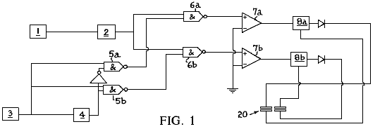
Fig.1 is a circuit diagram of fracture cell apparatus according to the invention;
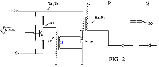
Fig.2 shows in more detail a part of the circuit diagram of Figure 1;
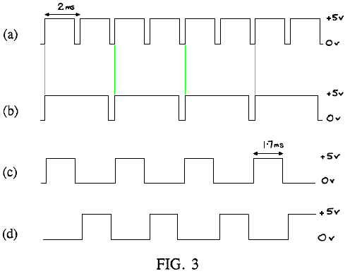
Fig.3 shows the different waveforms at various parts of the circuit diagram of Fig.1;
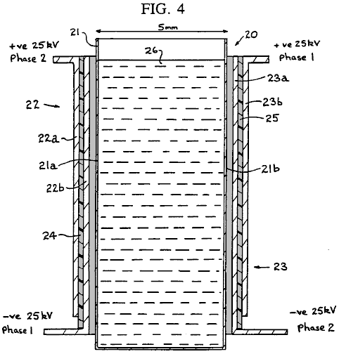
Fig.4 is a schematic diagram of a fracture cell for use in fracture cell apparatus according to the invention,
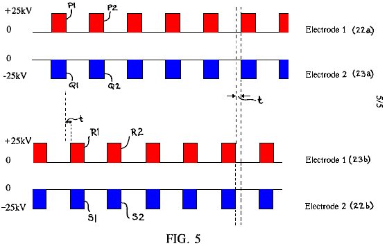
Fig.5 shows trains of pulses applied to electrodes of the fracture cell apparatus according to the invention.
If a large electric field is applied across a pair of electrode plates positioned either side of a cell containing water, disruption of the water molecules will occur. Such disruption yields hydrogen nuclei and HO- ions. Such a molecular disruption is of little interest in terms of obtaining a usable result from the cell. A proton-rich zone exists for as long as the field exists and quickly re-establishes equilibrium ion-product when the field is removed.
One noticeable side-effect, however, is that the hydroxyl ions (which will migrate to the +ve charged plate) are stripped of electrons as they approach the cell boundary. Any negatively-charged ion will exhibit this behaviour in a strong enough potential well, but the OH ions have a strong tendency to such dissociation. This results, momentarily, in a region of negative-charge close to the positive cell boundary. Thus, on opposite sides of the active cell, there are hydrogen nuclei (free proton zone) and displaced electrons (-ve charge zone), both tending to increase in density closer to the charged plates.
If, at this point, the charge is removed from the plates, there is a tendency for the charge-zones to move, albeit very slowly, towards the centre of the active cell. The ion-transit rates of free electrons and of hydrogen nuclei are, however, some two orders of magnitude greater than either H30+ ions or OH ions.
If the charges are now replaced on the plates, but with opposite polarity, the interesting and potentially useful aspect of the process is revealed. Hydrogen nucleus migration is accelerated in the direction of the new -ve plate and free electron migration takes place towards the new +ve plate. Where there is a sufficient concentration of both species, including the accumulations due to previous polarity changes, monatomic hydrogen is formed with the liberation of some heat energy. Normal molecular association occurs and H2 gas bubbles off from the cell.
Also existing OH radicals are further stripped of hydrogen nuclei and contribute to the process. Active, nascent 0-- ions rapidly lose their electronic space charge to the +ve field and monatomic oxygen forms, forming the diatomic molecule and similarly bubbling off from the cell.
Thus, the continuous application of a strong electric field, changing in polarity every cycle, is sufficient to disrupt water into its constituent gaseous elements, utilising a small fraction of the energy required in conventional electrolysis or chemical energetics, and yielding heat energy of the enthalpy of formation of the diatomic bonds in the hydrogen and oxygen.
Apparatus for performing the above process is described below. In particular, electronic circuitry to effect the invention is shown in the simplified block diagram of Fig.1. In Fig.1 a pulse-repetition frequency (PRF) generator 1 comprises an astable multivibrator clock running at a frequency which is preset for any application, but able to be varied across a range of approximately 5-30 kHz. The generator 1 drives, by triggering with the trailing edge of its waveform, a pulse-width (PW) timer 2.
The output of the timer 2 is a train of regular pulses whose width is determined by the setting of timer 2 and whose repetition frequency is set by the PRF generator 1.
A gate clock 3 comprises a simple 555-type circuit which produce a waveform (see Fig.3a) having a period of 1 to 5 ms, e.g. 2 ms as shown in Fig.3a. The duty cycle of this waveform is variable from 50% to around 95%. The waveform is applied to one input of each of a pair of AND gates 5a and 5b and also to a binary divide-by-two counter 4. The output of the counter 4 is shown in Fig.3b.
The signal from the divide-by-two counter 4 is applied directly to the AND gate 5b serving phase-2 driver circuitry 7a but is inverted before application to the AND gate 5a serving phase-l driver circuitry 7a. The output of the AND gate 5a is therefore ((CLOCK and (NOT (CLOCK)/2)) and the output of the AND gate 5b is ((CLOCK) and (CLOCK/2)), the waveforms, which are applied to pulse-train gates 6a and 6b, being shown in Fig.3c and Fig.3d.
Trains of 5-30 kHz pulses are applied to drive amplifiers 7a and 7b alternately, with a small "off"-period during which no pulses are applied to either amplifier. The duration of each "off" period is dependent upon the original duty cycle of the clock timer 3. The reason for the small "off" period in the driver waveforms is to prevent local corona arc as the phases change over each cycle.
The drive amplifiers 7a and 7b each use a BC182L transistor 10 (see Fig.2), small toroidal 2:1 pulse transformer 11 and a BUZll power-MOSFET 12 and apply pulse packets across the primary windings of their respective 25 kV line-output transformers 8a and 8b to produce an EHT ac voltage of high frequency at their secondary windings. The secondary windings are 'lifted' from system ground and provide, after simple half-wave rectification, the applied field for application to cell 20 (see Fig.4).
Cell 20 comprises a container 21 having walls 21a, 21b of electrically insulating material, e.g. a thermoplastics material, such as polymethyl methacrylate, typically spaced about 5 mm apart, and bipolar cell electrodes generally designated 22 and 23 and typically constructed from aluminium foil, positioned outside the walls 21a and 21b. Each bipolar cell electrode comprises a pair of electrode plates 22a and 22b (or 23a and 23b) for each side of the cell 20 separated from each other by an electrically insulating layer 24 (or 25) , e.g. of polycarbonate plastics material about 0.3 mm thick.
The electrode plates 22a and 23a form one set (set A) of electrode plates positioned on opposite sides of container 21 and the electrode plates 22b and 23b form another set of electrode plates positioned on opposite sides of the container 21. An insulating layer 25, e.g. of polycarbonate material, similar to the insulating layers 24a or 24b may be positioned between each bipolar cell electrode 22 (or 23) and its adjacent container wall 21a(or 21b). A liquid electrolyte, preferably water, is placed in the container 21.
In use, a train of positive pulses is applied to the electrode plates 22a and 23b and a train of negative pulses is applied to the electrode plates 23a and 22b. The timing of the pulses is shown schematically in Fig.5, which illustrates that, for set A (or for set B), whenever a positive pulse is applied to electrode plate 22a (or 23b), a negative pulse is also applied to electrode plate 23a (or 22b). However the pulses applied to the electrode plate set A are "out of phase" with the pulses applied to the electrode plate set B. In each train of pulses, the duration of each pulse is less than the gap between successive pulses.
By arranging for the pulses of electrode plate set B to be applied in the periods when no pulses are applied to the electrode plate set A, the situation arises where pairs of pulses are applied successively to the electrode plates of different sets of electrode plates, there being a short interval of time when no pulses are applied between each successive application of pulses to pairs of electrode plates. In other words, looking at Fig.5, pulses P1 and Q1 are applied at the same time to the electrode plates 22a and 23a. The pulses P1 and Q1 are of the same pulse length and, at the end of their duration, there is a short time period t before pulses R1 and S1 are applied to the electrode plates 23b and 22b.
The pulses R1 and S1 are of the same pulse length as the pulses P1 and Q1 and, at the end of their duration, there is a further time t before the next pulses P2 and Q2 are applied to the electrode plates 22a and 23a. It will be appreciated that whenever a pulse of one sign is applied to one of the electrode plates of a set, a pulse of the opposite sign is applied to the other electrode plate of that set.
Furthermore, by switching from one to the other electrode plate set the polarities applied across the container are repeatedly switched resulting in an "alternating" electric field being created across the "liquid dielectric" water in the container.
The
Electrolyser of Spiro Spiros
Patent WO 9528510
26th October 1995
Inventor: Spiro Ross Spiros
IMPROVEMENTS IN ELECTROLYSIS SYSTEMS
& THE AVAILABILITY OF OVER-UNITY
ENERGY
This patent application shows the details of an electrolyser system which it is claimed, produces greater output than the input power needed to operate it.
ABSTRACT
A looped energy system for the generation of excess energy available to do work is disclosed. The system comprises an electrolysis cell unit 150 receiving a supply of water to liberate separated hydrogen gas 154 and oxygen 156 by electrolysis driven by a DC voltage 152 applied across respective anodes and cathodes of the cell unit 150. A hydrogen gas receiver 158 receives and stores hydrogen gas liberated by the cell unit 150, and an oxygen gas receiver 160 receives and stores oxygen gas liberated by the cell unit 150. A gas expansion device 162 expands the stored gases to recover expansion work, and a gas combustion device 168 mixes and combusts the expanded hydrogen gas and oxygen gas to recover combusted work. A proportion of the sum of the expansion work and the combustion work sustains electrolysis of the cell unit to retain operational gas pressure in the gas receivers 158, 160 such that the energy system is self-sustaining, and there is excess energy available from the sum of energies.
TECHNICAL
FIELD OF THE INVENTION
The present invention relates to the generation of hydrogen gas and oxygen gas from water, either as an admixture or as separated gases, by the process of electrolysis, and relates further to applications for the use of the liberated gas. Embodiments of the invention relate particularly to apparatus for the efficient generation of these gases, and to use of the gases in an internal combustion engine and an implosion pump. The invention also discloses a closed-loop energy generation system where latent molecular energy is liberated as a form of 'free energy' so the system can be self-sustaining.
Reference is made to commonly-owned International patent application No. PCT/AU94/000532, having the International filing date of 6 September 1994.
Background Art
The technique of electrolysing water in the presence of an electrolyte such as sodium hydroxide (NaOH) or potassium hydroxide (KOH) to liberate hydrogen and oxygen gas (H2, 02) is well known. The process involves applying a DC potential difference between two or more anode/cathode electrode pairs and delivering the minimum energy required to break the H-O bonds (i.e. 68.3 kcal per mole @ STP).
The gases are produced in the stoichiometric proportions for O2:H2 of 1:2 liberated respectively from the anode (+) and cathode (-).
Reference can be made to the following texts:
"Modern Electrochemistry, Volume 2, John O'M. Bockris and Amulya K.N. Reddy, Plenum Publishing Corporation",
"Electro-Chemical Science, J. O'M. Bockris and D.M. Drazic, Taylor and Francis Limited" and
"Fuel Cells, Their Electrochemistry, J. O'M. Bockris and S. Srinivasan, McGraw-Hill Book Company".
A discussion
of experimental work in relation to electrolysis processes can be obtained from
"Hydrogen Energy, Part A, Hydrogen Economy Miami Energy Conference,
On a macro-scale, the amount of gas produced depends upon a number of variables, including the type and concentration of the electrolytic solution used, the anode/cathode electrode pair surface area, the electrolytic resistance (equating to ionic conductivity, which is a function of temperature and pressure), achievable current density and anode/cathode potential difference. The total energy delivered must be sufficient to disassociate the water ions to generate hydrogen and oxygen gases, yet avoid plating (oxidation/reduction) of the metallic or conductive non-metallic materials from which the electrodes are constructed.
DISCLOSURE OF THE INVENTION
The invention discloses a looped-energy system for the generation of excess energy available to do work, the said system comprising of:
An electrolysis cell unit receiving a supply of water for liberating separated hydrogen gas and oxygen gas by electrolysis due to a DC voltage applied across respective anodes and cathodes of the cell;
A hydrogen gas receiver to receive and store the hydrogen gas liberated by the electrolysis cell;
An oxygen gas receiver to receive and store the oxygen gas liberated by the electrolysis cell;
A gas-expansion chamber to allow the expansion of the stored gases to recover expansion work; and
A gas-combustion mechanism for mixing and combusting the expanded hydrogen and oxygen gases to recover combustion work; and wherein a proportion of the sum of the expansion work and the combustion work sustains the electrolysis of the electrolysis cell in order to retain the operational gas pressure in the hydrogen and oxygen gas receivers so that the energy system is self-sustaining and there is excess energy available.
The invention further discloses a method for the generation of excess energy available to do work by the process of electrolysis, said method comprising the steps of: electrolysing water by a DC voltage to liberate separated hydrogen gas and oxygen gas; separately receiving and storing the hydrogen and oxygen gases in a manner to be self-pressuring; separately expanding the stored gas to recover expansion energy; burning the expanded gases to recover combustion energy; and applying a portion of the sum of the expansion work and the combustion work as the DC voltage to retain operational gas pressures and sustain the electrolysis, there being excess energy available to do this.
The invention also discloses an internal combustion engine powered by hydrogen and oxygen comprising of:
At least one cylinder and
At least one reciprocating piston within the cylinder;
A hydrogen gas input port in communication with the cylinder for receiving a supply of pressurised hydrogen;
An oxygen gas input port in communication with the cylinder for receiving a supply of pressurised oxygen; and
An exhaust port in communication with the cylinder and wherein the engine can be operated in a two-stroke manner whereby, at the top of the stroke, hydrogen gas is supplied through the respective inlet port to the cylinder driving the piston downwards, oxygen gas then is supplied through the respective inlet port to the cylinder to drive the cylinder further downwards, after which time self-detonation occurs and the piston moves to the bottom of the stroke and upwards again with the exhaust port opened to force out the water vapour resulting from the detonation.
The invention also discloses an implosion pump comprising of;
A combustion chamber interposed, and in communication with,
An upper reservoir and a lower reservoir separated by a vertical distance across which water is to be pumped, this chamber receiving admixed hydrogen and oxygen at a pressure sufficient to lift a volume of water the distance from there to the top reservoir, the gas in the chamber then being ignited to create a vacuum in the chamber to draw water from the lower reservoir to fill the chamber, whereupon a pumping cycle is established and can be repeated.
The invention also discloses a parallel stacked arrangement of cell plates for a water electrolysis unit, the cell plates alternately forming an anode and cathode of the electrolysis unit, and the arrangement including separate hydrogen gas and oxygen gas outlet ports respectively linked to the anode cell plates and the cathode cell plates and extending longitudinally along the plate stack. These outlet ports are arranged so as to be insulated from the anode and cathode plates.
DESCRIPTION
OF THE DRAWINGS
Figs.1 1a-16 of noted International application no. PCT/AU94/000532 are reproduced to aid description of the present invention, but herein denoted as Figs.la-6:
Fig.1A and Fig.1B show an embodiment of a cell plate:
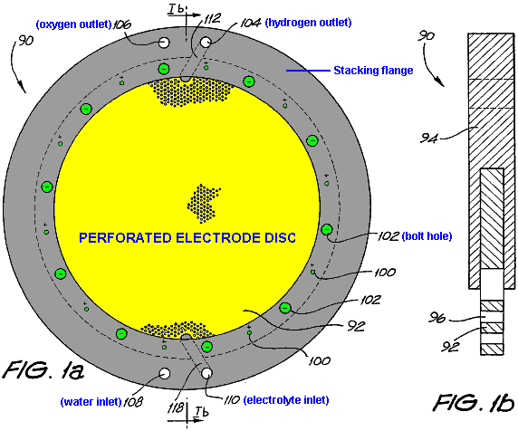
Fig.2A and Fig.2B show a complementary cell plate to that of Fig.lA and Fig1B:
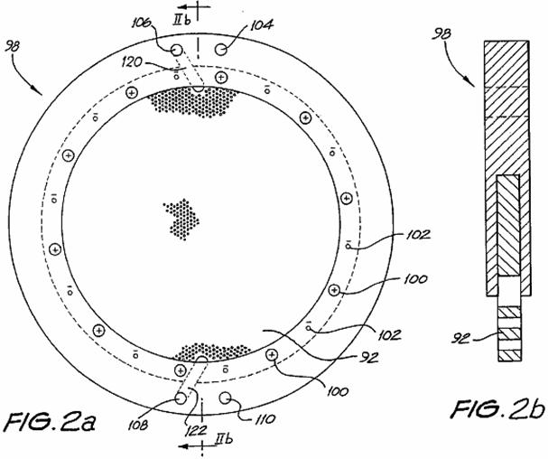
Fig.3 shows detail of the perforations and porting of the cell plates of Figs. lA,lB, 2A and 2B:
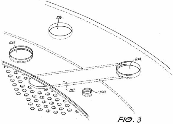
Fig.4 shows an exploded stacked arrangement of the cell plates of Figs. lA,lB, 2A and 2B:
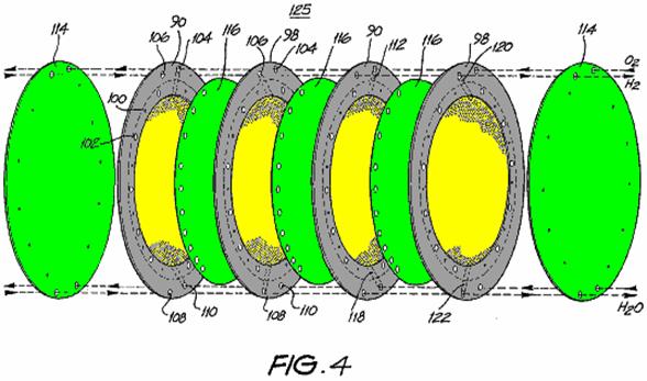
Fig.5A shows a schematic view of the gas separation system of Fig.4:

Fig.5B shows a stylised representation of Fig.5a:
Fig.5C shows an electrical equivalent circuit of Fig.5A and
Fig.6 shows a gas collection system for use with the cell bank separation system of Figs. 4 and 5a.
The remaining drawings are:
Fig.7A and Fig.7B are views of a first cell plate:
Fig.8A and Fig.8B are views of a second cell plate:
Fig.9 shows detail of the edge margin of the first cell plate:

Fig10 shows an exploded stacked arrangement of the cell plates shown in Fig.7A and Fig.8A:
Fig.11 is a cross-sectional view of three of the stacked cell plates shown in Fig.10 in the vicinity of a gas port:
Fig.12A and Fig.12B respectively show detail of the first and second cell plates in the vicinity of a gas port:
Fig.13 is a cross-sectional view of a cell unit of four stacked cell plates in the vicinity of an interconnecting shaft:
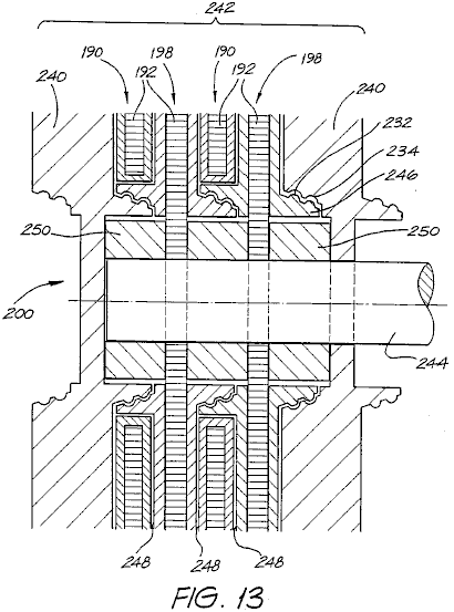
Fig.14 shows a perspective view of a locking nut used in the arrangement of Fig.13:
Fig.15 shows an idealised electrolysis system:
Figs.16-30 are graphs supporting the system of Fig.15 and the availability of over-unity energy:
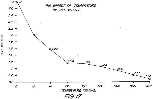
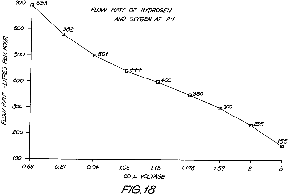
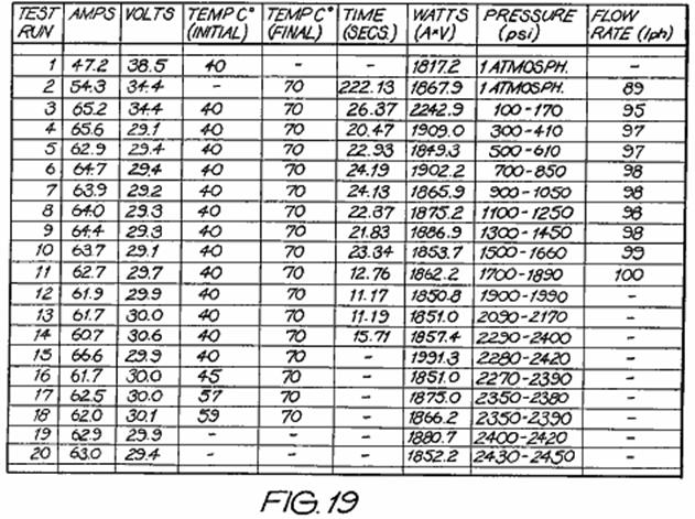
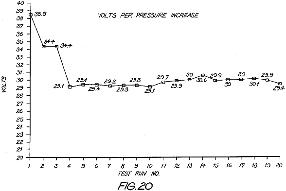
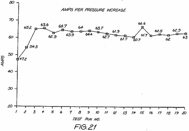
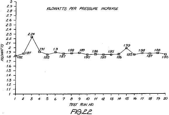
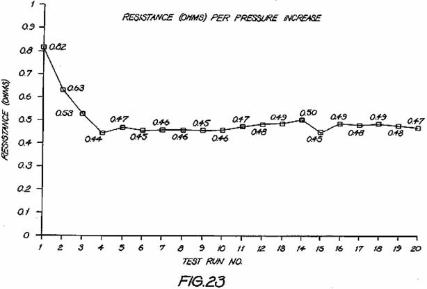

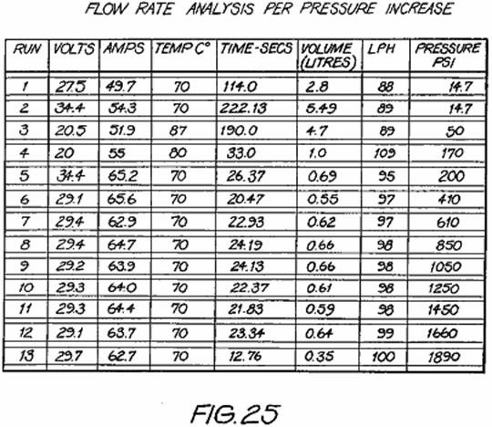
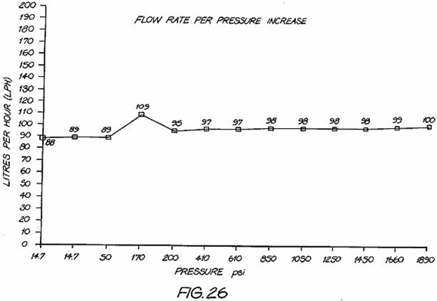
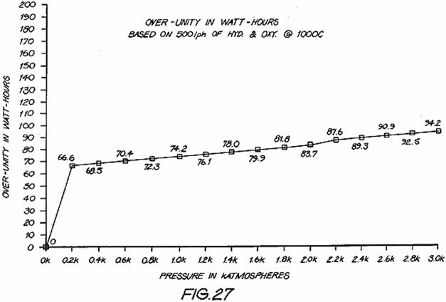

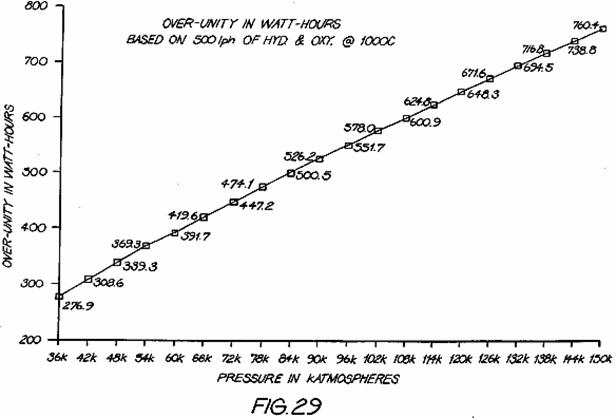
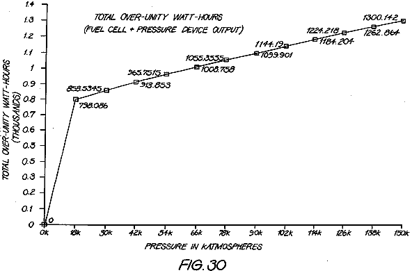
Figs. 31a to 31e show a hydrogen/oxygen gas-driven internal combustion engine:
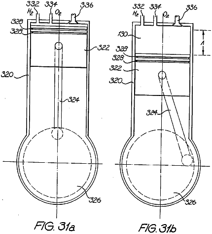
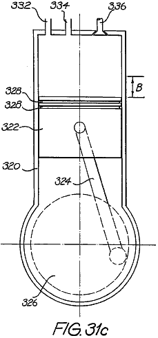
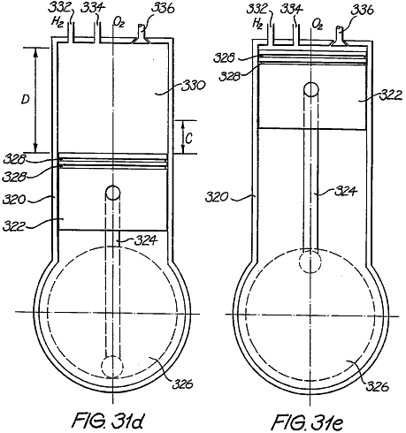
Figs. 32a-32c show a gas-driven implosion pump:
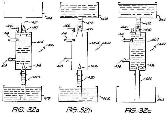
DETAILED
DESCRIPTION AND BEST MODE OF PERFORMANCE
Fig.lA and Fig.2A show embodiments of a first and second type of cell plate 90, 98 as an end view. Fig.1B and Fig.2B are partial cross-sectional views along the respective mid-lines as shown. Common reference numerals have been used where appropriate. The plates 90, 98 can have the function of either an anode (+) or a cathode (-), as will become apparent. Each comprises an electrode disc 92 which is perforated with hexagonally shaped holes 96. The disc 92 is made from steel or resin-bonded carbon or conductive polymer material. The disc 92 is housed in a circular rim or sleeve 94. The function of the perforations 96 is to maximise the surface area of the electrode disc 92 and minimise the weight over solid constructions by 45%.
By way of example, for a disc of diameter 280 mm, the thickness of the disc must be 1 mm in order to allow the current density (which ranges from 90 A / 2,650 cm2 - 100 A / 2,940 cm2 of the anode or cathode) to be optimal. If the diameter of the plate is increased, which consequently increases the surface area, it is necessary to increase the thickness of the plate in order to maintain uniformity of conductance for the desired current density.
The hexagonal perforations in a 1 mm disc have a distance of 2 mm between the flats, twice the thickness of the plate in order to maintain the same total surface area prior to perforation, and be 1 mm away from the next adjacent perforation to allow the current density to be optimal. A (flat-to-flat) distance of 1 mm between the hexagonal perforations is required, because a smaller distance will result in thermal losses and a larger distance will add to the overall weight of the plate.
The sleeve 94 is constructed of PVC material and incorporates a number of equally spaced shaft holes 100,102. The holes are for the passage of interconnecting shafts provided in a stacked arrangement of the plates 90, 98 forming the common conductor for the respective anode and cathode plates. The further two upper holes 104,106 each support a conduit respectively for the out-flow of oxygen and hydrogen gases. The further holes 108,110 at the bottom of the sleeve 94 are provided for the inlet of water and electrolyte to the respective cell plates 90, 98.
Fig.3 shows an enlarged view of a portion of the cell plate 90 shown in Fig.lA. The port hole 104 is connected to the hexagonal perforations 96 within the sleeve 94 by an internal channel 112. A similar arrangement is in place for the other port hole 106, and for the water/electrolyte supply holes 108, 110.
If it is the case that the hydrogen and oxygen gases liberated are to be kept separate (i.e. not to be formed as an admixture), then it is necessary to separate those gases as they are produced. In the prior art this is achieved by use of diaphragms which block the passage of gases and effectively isolate the water/electrolyte on each side of the diaphragm. Ionic transfer thus is facilitated by the conductive nature of the diaphragm material (i.e. a water - diaphragm - water path). This results in an increase in the ionic resistance and hence a reduction in efficiency.
Fig.4 shows an exploded stacked arrangement of four cell plates, being an alternative stacking of two (anode) cell plates 90 and two (cathode) cell plates 98. The two ends of the stacked arrangement of cell plates delineates a single cell unit 125.
Interposed between each adjacent cell plate 90, 98 is a PTFE separation 116. Although not shown in Fig.4, the cell unit includes separate hydrogen and oxygen gas conduits that respectively pass through the stacked arrangement of cell plates via the port holes 106, 104 respectively. In a similar way, conduits are provided for the supply of water/electrolyte, respectively passing through the holes 108, 110 at the bottom of the respective plates 90, 98. Only two pairs of anode/cathode cell plates are shown. The number of such plates can be greatly increased per cell unit 125.
Also not shown are the interconnecting conductive shafts that electrically interconnect alternative common cell plates. The reason for having a large diameter hole in one cell plate adjacent to a smaller diameter hole in the next cell plate, is so that an interconnecting shaft will pass through the larger diameter hole, and not make an electrical connection (i.e. insulated with PVC tubing) rather only forming an electrical connection between alternate (common) cell plates.
Fig.4 is an exploded view of one cell unit 125 arrangement. When fully constructed, all the elements are stacked in intimate contact. Mechanical fastening is achieved by use of one of two adhesives such as (a) "PUR-FECT LOK" (TM) 34-9002, which is a Urethane Reactive Hot Melt adhesive with a main ingredient of Methylene Bispheny/Dirsocynate (MDI), and (b) "MY-T-BOND" (TM) which is a PVC solvent based adhesive. Both adhesives are Sodium Hydroxide resistant, which is necessary because the electrolyte contains 20% Sodium Hydroxide. In that case the water/electrolyte only resides within the area contained within the cell plate sleeve 94. Thus the only path for the inlet of water/electrolyte is by bottom channels 118, 122 and the only outlet for the gases is by the top channels 112, 120. In a system constructed and tested by the inventor, the thickness of the cell plates 90, 98 is 1 mm (2 mm on the rim because of the PVC sleeve 94), with a diameter of 336 mm. The cell unit 125 is segmented from the next cell by an insulating PVC segmentation disc 114. A segmentation disc 114 is also placed at the beginning and end of the entire cell bank. If there is to be no separation of the liberated gases, then the PTFE membranes 116 are omitted and sleeve 94 is not required.
The PTFE membrane 116 is fibrous and has 0.2 to 1.0 micron interstices. A suitable type is type Catalogue Code J, supplied by Tokyo Roshi International Inc (Advantec). The water/electrolyte fills the interstices and ionic current flows only via the water - there is no contribution of ionic flow through the PTFE material itself. This leads to a reduction in the resistance to ionic flow. The PTFE material also has a 'bubble point' that is a function of pressure, hence by controlling the relative pressures at either side of the PTFE separation sheets, the gases can be 'forced' through the interstices to form an admixture, or otherwise kept separate. Other advantages of this arrangement include a lesser cost of construction, improved operational efficiency and greater resistance to faults.
Fig.5A is a stylised, and exploded, schematic view of a linear array of three series-connected cell units 125. For clarity, only six interconnecting shafts 126-131 are shown. The shafts 126-131 pass through the respective shaft holes 102,100 in the various cell plates 90,98 in the stacked arrangement. The polarity attached to each of the exposed end shafts, to which the DC supply is connected also is indicated. The shafts 126-131 do not run the full length of the three cell banks 125. The representation is similar to the arrangement shown in Fig.7A and Fig.8. One third the full DC source voltage appears across each anode/cathode cell plate pair 90,98.
Further, the gas conduits 132,133, respectively for hydrogen and oxygen, that pass through the port holes 104,106 in the cell plates 90,98 also are shown. In a similar way, water/electrolyte conduits 134,135, passing through the water port holes 108,110 in the cell plates also are shown.
Fig.5B particularly shows how the relative potential difference in the middle cell bank 125 changes. That is, the plate electrode 90a now functions as a cathode (i.e. relatively more negative) to generate hydrogen, and the plate electrode 98a now functions as an anode (i.e. relatively more positive) to generate oxygen. This is the case for every alternate cell unit. The arrowheads shown in Fig.5B indicate the electron and ionic current circuit. Fig.5C is an electrical equivalent circuit representation of Fig.5B, where the resistive elements represent the ionic resistance between adjacent anode/cathode plates. Thus it can be seen that the cell units are connected in series.
Because of the change of function of the cell plates 90a and 98a, the complementary gases are liberated at each, hence the respective channels 112 are connected to the opposite gas conduit 132,133. Practically, this can be achieved by the simple reversal of the cell plates 90,98.
Fig.6 shows the three cell units 125 of Fig.5A connected to a gas collection arrangement. The cell units 125 are located within a tank 140 which is filled with water/electrolyte to the indicated level h. The water is consumed as the electrolysis process proceeds, and replenishing supply is provided via the inlet 152. The water/electrolyte level h can be viewed via the sight glass 154. In normal operation, the different streams of hydrogen and oxygen are produced and passed from the cell units 125 to respective rising columns 142,144. That is, the pressure of electrolyte on opposed sides of the PTFE membranes 116 is equalised, thus the gases cannot admix.
The columns 142,144 also are filled with the water/electrolyte, and as it is consumed at the electrode plates, replenishing supply of electrolyte is provided by way of circulation through the water/electrolyte conduits 134,135. The circulation is caused by entrainment by the liberated gases, and by the circulatory inducing nature of the conduits and columns.
The upper extent of the tank 140 forms two scrubbing towers 156,158, respectively for the collection of oxygen and hydrogen gases. The gases pass up a respective column 142,144, and out from the columns via openings therein at a point within the interleaved baffles 146. The point where the gases exit the columns 142,144 is beneath the water level h, which serves to settle any turbulent flow and entrained electrolyte. The baffles 146 located above the level h scrub the gas of any entrained electrolyte, and the scrubbed gas then exits by respective gas outlet columns 148,150 and so to a gas receiver. The level h within the tank 140 can be regulated by any convenient means, including a float switch, again with the replenishing water being supplied by the inlet pipe 152.
The liberated gases will always separate from the water/electrolyte solution by virtue of the difference in densities. Because of the relative height of the respective set of baffles, and due to the density differential between the gases and the water/electrolyte, it is not possible for the liberated hydrogen and oxygen gases to mix. The presence of the full volume of water within the tank 140 maintains the cell plates in an immersed state, and further serves to absorb the shock of any internal detonations should they occur.
In the event that a gas admixture is required, then firstly the two flow valves 136,137 respectively located in the oxygen gas outlet conduit 132 and water/electrolyte inlet port 134 are closed. This blocks the outlet path for the oxygen gas and forces the inlet water/electrolyte to pass to the inlet conduit 134 via a one-way check valve 139 and pump 138. The water/electrolyte within the tank 140 is under pressure by virtue of its depth (volume), and the pump 138 operates to increase the pressure of water/electrolyte occurring about the anode cell plates 90,98a to be at an increased pressure with respect to the water/electrolyte on the other side of the membrane 116.
This pressure differential is sufficient to cause the oxygen gas to migrate through the membrane, thus admixed oxygen and hydrogen are liberated via the gas output conduit 133 and column 144. Since there is no return path for the water/electrolyte supplied by the pump 138, the pressure about the cell plates 90,98a will increase further, and to a point where the difference is sufficient such that the water/electrolyte also can pass through the membrane 116. Typically, pressure differential in the range of 1.5 - 10 psi is required to allow passage of gas, and a pressure differential in the range of 10 - 40 psi for water/electrolyte.
While only three cell units 125 are shown, clearly any number, connected in series, can be implemented.
Embodiments of the present invention now will be described. Where applicable, like reference numerals have been used.
Fig.7A and Fig.7B show a first type of cell plate 190 respectively as an end view and as an enlarged cross-sectional view along line VIIb-VIIb. The cell plate 190 differs from the previous cell plate 90 shown in Fig.1A and Fig.1B in a number of important aspects. The region of the electrode disc 192 received within the sleeve 194 now is perforated. The function of these perforations is to further reduce the weight of the cell plate 190. The shaft holes 200,202 again pass through the electrode disc 192, but so too do the upper holes 204,206 through which the conduits for the out-flow of liberated hydrogen and oxygen gases pass. The bottom holes 208,210, provided for the inlet of water and electrolyte, now also are located in the region of the sleeve 194 coincident with the perforated edge margin of the electrode disc 192. The channels 212,218 respectively communicating with the port hole 204 and the supply hole 210 also are shown.
Fig.8A and Fig.8B show a second type of cell plate 198 as a companion to the first cell plate 190, and as the same respective views. The second cell plate 198 is somewhat similar to the cell plate 98 previously shown in Fig.2A and Fig.2B. The differences between them are the same as the respective differences between the cell plate shown in Fig.1A and Fig.1B and the one shown in Fig.7A and Fig.7B. The arrangement of the respective channels 220,222 with respect to the port 206 and the water supply hole 208 also are shown.
In the fabrication of the cell plates 190,198, the sleeve 94 is injection moulded from PVC plastics material formed about the edge margin of the electrode disc 192.
The injection moulding process results in the advantageous forming of interconnecting sprues forming within the perforations 196 in the region of the disc 192 held within the sleeve 194, thus firmly anchoring the sleeve 194 to the disc 192.
Fig.9 is a view similar to Fig.3, but for the modified porting arrangement and perforations (shown in phantom where covered by the sleeve) of the region of the disc 192 within and immediately outside of the sleeve 194.
Fig.10 shows a cell unit 225 in the form of an exploded alternating stacking of first and second cell plates 190,198, much in the same manner as Fig.4. Only two pairs of anode/cathode cell plates are shown, however the number of such plates can be greatly increased per cell unit 225. The membrane 216 preferably is type QR-HE silica fibre with the alternative being PTFE. Both are available from Tokyo Roshi
International
Inc. (Advantec) of
Furthermore, the cell units can be put to use in a gas collection arrangement such as that shown in Fig.6. Operation of the gas separation system utilising the new cell plates 190,198 is in the same manner as previously described.
Fig.11 is an enlarged cross-sectional view of three cell plates in the vicinity of the oxygen port 204. The cell plates comprise two of the first type of plate 190 shown in Fig.7A constituting a positive plate, and a single one of the second type of plate 198 shown in Fig.8A representing a negative plate. The location of the respective channels 212 for each of the positive cell plates 190 is shown as a dashed representation. The respective sleeves 194 of the three cell plates are formed from moulded PVC plastics as previously described, and in the region that forms the perimeter of the port 204 have a configuration particular to whether a cell plate is positive or negative. In the present case, the positive cell plates 190 have a flanged foot 230 that, in the assembled construction, form the contiguous boundary of the gas port 204. Each foot 230 has two circumferential ribs 232 which engage corresponding circumferential grooves 234 in the sleeve 194 of the negative plate 198.
The result of this arrangement is that the exposed metal area of the negative cell plates 198 always are insulated from the flow of oxygen gas liberated from the positive cell plates 190, thus avoiding the possibility of spontaneous explosion by the mixing of the separated hydrogen and oxygen gases. This arrangement also overcomes the unwanted production of either oxygen gas or hydrogen gas in the gas port.
For the case of the gas port 206 carrying the hydrogen gas, the relative arrangement of the cell plates is reversed such that a flanged footing now is formed on the sleeve 194 of the other type of cell plate 198. This represents the converse arrangement to that shown in Fig.11.
Fig.12A and Fig.12B show perspective side views of adjacent cell plates, with Fig.12A representing a positive cell plate 190 and Fig.12B representing a negative cell plate 198. The gas port 206 thus formed is to carry hydrogen gas. The mating relationship between the flanged foot 230 and the end margin of the sleeve 194 of the positive cell plate 192 can be seen, particularly the interaction between the ribs 232 and the grooves 234.
Fig.13 is a cross-sectional view of four cell plates formed into a stacked arrangement delimited by two segmentation plates 240, together forming a cell unit 242. Thus there are two positive cell plates 190 and two negative cell plates 198 in alternating arrangement. The cross-section is taken in the vicinity of a shaft hole 202 through which a negative conductive shaft 244 passes. The shaft 244 therefore is in intimate contact with the electrode discs 192 of the negative cell plates 198. The electrodes discs 192 of the positive cell plates 190 do not extend to contact the shaft 244. The sleeve 194 of the alternating negative cell plates 198 again have a form of flanged foot 246, although in this case the complementarily shaped ribs and grooves are formed only on the sleeve of the negative cell plates 198, and not on the sleeve 194 of the positive cell plates 190. The segmentation plates 240 serve to delimit the stacked plates forming a single cell unit 242, with ones of the cell units 242 being stacked in a linear array to form a cell bank such as has been shown in Fig.5A.
A threaded shaft nut 250 acts as a spacer between adjacent electrodes connecting with the shaft 244. Fig.14 is a perspective view of the shaft nut 250 showing the thread 252 and three recesses 254 for fastening nuts, screws or the like.
In all of Figs.11 to 13, the separation membrane material 216 is not shown, but is located in the spaces 248 between adjacent cell plates 190,198, extending to the margins of the electrode disks 192 in the vicinity of the gas ports 204,206 or the shaft holes 200,202.
An electrolysis hydrogen and oxygen gas system incorporating a gas separation system, such as has been described above, can therefore be operated to establish respective high pressure stores of gas. That is, the separated hydrogen and oxygen gases liberated by the electrolysis process are stored in separate gas receivers or pressure vessels. The pressure in each will increase with the continuing inflow of gas.
Fig.15 shows an idealised electrolysis system, comprising an electrolysis cell 150 that receives a supply of water to be consumed. The electrolysis process is driven by a DC potential (Es) 152. The potential difference applied to the cell 150 therefore must be sufficient to electrolyse the water into hydrogen and oxygen gas dependent upon, inter alia, the water pressure PC and the back pressure of gas PB acting on the surface of the water, together with the water temperature Tc. The separate liberated hydrogen and oxygen gases, by a priming function, are pressurised to a high value by storage in respective pressure vessels 158,160, being carried by gas lines 154,156.
The pressurised store of gases then are passed to an energy conversion device that converts the flow of gas under pressure to mechanical energy (e.g. a pressure drop device 162). This mechanical energy recovered WM is available to be utilised to provide useful work. The mechanical energy WM also can be converted into electrical form, again to be available for use.
The resultant exhausted gases are passed via lines 164,166 to a combustion chamber 168. Here, the gases are combusted to generate heat QR, with the waste product being water vapour. The recovered heat QR can be recycled to the electrolysis cell to assist in maintaining the advantageous operating temperature of the cell.
The previously described combustion chamber 168 can alternatively be a fuel cell. The type of fuel cell can vary from phosphoric acid fuel cells through to molten carbonate fuel cells and solid oxide cells. A fuel cell generates both heat (QR) and electrical energy (WE), and thus can supply both heat to the cell 150 or to supplement or replace the DC supply (Es) 152.
Typically,
these fuel cells can be of the type LaserCell TM as developed by Dr Roger Billings, the PEM
Cell as available from Ballard Power Systems Inc. Canada or the Ceramic Fuel
Cell (solid oxide) as developed by Ceramic Fuel Cells Ltd.,
It is, of course, necessary to replenish the pressurised store of gases, thus requiring the continuing consumption of electrical energy. The recovered electrical energy WE is in excess of the energy required to drive electrolysis at the elevated temperature and is used to replace the external electrical energy source 152, thereby completing the energy loop after the system is initially primed and started.
The present inventor has determined that there are some combinations of pressure and temperature where the efficiency of the electrolysis process becomes advantageous in terms of the total energy recovered, either as mechanical energy by virtue of a flow of gas at high pressure or as thermal energy by virtue of combustion (or by means of a fuel cell), with respect to the electrical energy consumed, to the extent of the recovered energy exceeding the energy required to sustain electrolysis at the operational pressure and temperature. This has been substantiated by experimentation. This notion has been termed "over-unity".
"Over-unity" systems can be categorised as broadly falling into three types of physical phenomena:
(i) An electrical device which produces 100 Watts of electrical energy as output after 10 Watts of electrical energy is input thereby providing 90 Watts of overunity (electrical) energy.
(ii) An electro-chemical
device such as an electrolysis device where
(iii) An electro-chemical device which produces an excess of thermal energy after an input of electrical energy in such devices utilised in "cold fusion" e.g. 10 watts of electrical energy as input and 50 watts of thermal energy as output.
The present invention represents the discovery of means by which the previously mentioned second phenomenon can be embodied to result in "over-unity" and the realisation of 'free' energy. As previously noted, this is the process of liberating latent molecular energy. The following sequence of events describes the basis of the availability of over-unity energy.
In a simple two plate (anode/cathode) electrolysis cell, an applied voltage differential of 1.57 DC Volts draws 0.034 Amps per cm2 and results in the liberation of hydrogen and oxygen gas from the relevant electrode plate. The electrolyte is kept at a constant temperature of 400C, and is open to atmospheric pressure.
The inefficiency of an electrolytic cell is due to its ionic resistance (approximately 20%), and produces a by-product of thermal energy. The resistance reduces, as does the minimum DC voltage required to drive electrolysis, as the temperature increases. The overall energy required to dissociate the bonding electrons from the water molecule also decreases as the temperature increases. In effect, thermal energy acts as a catalyst to reduce the energy requirements in the production of hydrogen and oxygen gases from the water molecule. Improvements in efficiency are obtainable by way of a combination of thermal energy itself and the NaOH electrolyte both acting to reduce the resistance of the ionic flow of current.
Thermal 'cracking' of the water molecule is known to occur at 1,5000C, whereby the bonding electrons are dissociated and subsequently 'separate' the water molecule into its constituent elements in gaseous form. This thermal cracking then allows the thermal energy to become a consumable. Insulation can be introduced to conserve thermal energy, however there will always be some thermal energy losses.
Accordingly, thermal energy is both a catalyst and a consumable (in the sense that the thermal energy excites bonding electrons to a higher energetic state) in the electrolysis process. A net result from the foregoing process is that hydrogen is being produced from thermal energy because thermal energy reduces the overall energy requirements of the electrolysis system.
Referring to the graph titled "Flow Rate At A Given Temperature" shown in Fig.16, it has been calculated that at a temperature of 2,0000C, 693 litres of hydrogen/oxygen admixed gas (2:1) will be produced. The hydrogen content of this volume is 462 litres. At an energy content of 11 BTUs per litre of hydrogen, this then gives an energy amount of 5,082 BTUs (11 x 462). Using the BTU:kilowatt conversion factor of 3413:1, 5,082 BTUs of the hydrogen gas equate to 1.49 kW. Compare this with l kW to produce the 693 litres of hydrogen/oxygen (including 463 litres of hydrogen). The usage of this apparatus therefore identifies that thermal energy, through the process of electrolysis, is being converted into hydrogen. These inefficiencies, i.e. increased temperature and NaOH electrolyte, reduce with temperature to a point at approximately 10000C where the ionic resistance reduces to zero, and the volumetric amount of gases produced per kWh increases.
The lowering of DC voltage necessary to drive electrolysis by way of higher temperatures is demonstrated in the graph in Fig.17 titled "The Effect of temperature on Cell Voltage".
The data in Fig.16 and Fig.17 have two sources.
Cell voltages obtained from 00C up to and including 1000C were those
obtained by an electrolysis system as described above. Cell voltages obtained from 1500C up to 2,0000C are
theoretical calculations presented by an acknowledged authority in this field,
Prof. J. O'M. Bockris. Specifically,
these findings were presented in "Hydrogen Energy, Part A, Hydrogen
Economy”, Miami Energy Conference,
By inspection of Fig.17 and Fig.18 (titled "Flow Rate of Hydrogen and Oxygen at 2:1"), it can be seen that as temperature increases in the cell, the voltage necessary to dissociate the water molecule is reduced, as is the overall energy requirement. This then results in a higher gas flow per kWh.
As constrained by the limitation of the materials within the system, the operationally acceptable temperature of the system is 10000C. This temperature level should not, however, be considered as a restriction. This temperature is based on the limitations of the currently commercially available materials. Specifically, this system can utilise material such as compressed Silica Fibre for the sleeve around the electrolysis plate and hydrophobic Silica Fibre (part no. QR-100HE supplied by Tokyo Roshi International Inc., also known as "Advantec") for the diaphragm (as previously discussed) which separates the electrolysis disc plates. In the process of assembling the cells, the diaphragm material and sleeved electrolysis plates 190,198 are adhered to one another by using high-temperature-resistant silica adhesive (e.g. the "Aremco" product "Ceramabond 618" which has an operational tolerance specification of 1,0000C).
For the electrolysis cell described above, with the electrolyte at 1,0000C and utilising electrical energy at the rate of 1 kWh, 167 litres of oxygen and 334 litres of hydrogen per hour will be produced.
The silica fibre diaphragm 116 previously discussed separates the oxygen and hydrogen gas streams by the mechanism of density separation, and produce a separate store of oxygen and hydrogen at pressure. Pressure from the produced gases can range from 0 to 150,000 Atmospheres. At higher pressures, density separation may not occur. In this instance, the gas molecules can be magnetically separated from the electrolyte if required.
In reference to the experiments conducted by Messrs Hamann and Linton (S.D. Hamann and M. Linton, Trans. Faraday Soc. 62,2234-2241, specifically, page 2,240), this research has proven that higher pressures can produce the same effect as higher temperatures in that the conductivity increases as temperature and/or pressure increases. At very high pressures, the water molecule dissociates at low temperatures. The reason for this is that the bonding electron is more readily removed when under high pressure. The same phenomenon occurs when the bonding electrons are at a high temperature (e.g. 1,5000C) but at low pressures.
As shown in Fig.15, hydrogen and oxygen gases are separated into independent gas streams flowing into separate pressure vessels 158,160 capable of withstanding pressures up to 150,000 Atmospheres. Separation of the two gases thereby eliminates the possibility of detonation. It should also be noted that high pressures can facilitate the use of high temperatures within the electrolyte because the higher pressure elevates the boiling point of water.
Experimentation shows that 1 litre of water can yield 1,850 litres of hydrogen/oxygen (in a ratio of 2: 1) gas mix after decomposition, this significant differential(1:1,850) is the source of the pressure. Stripping the bonding electrons from the water molecule, which subsequently converts liquid into a gaseous state, releases energy which can be utilised as pressure when this occurs in a confined space.
A discussion
of experimental work in relation to the effects of pressure in electrolysis
processes can be obtained from "Hydrogen Energy, Part A, Hydrogen Economy
Miami Energy Conference,
Attention must be drawn to the above published material; specifically on page 434, third paragraph, where reference is made to "Fig.7 shows the effect of pressure on cell voltage...". Fig. 7 on page 436 ("Effect of Pressure on SFWES Single Cell") indicates that if pressure is increased, then so too does the minimum DC voltage.
These quotes were provided for familiarisation purposes only and not as demonstrable and empirical fact. Experimentation by the inventor factually indicates that increased pressure (up to 2,450 psi) in fact lowers the minimum DC voltage.
This now demonstrable fact, whereby increased pressure actually lowers minimum DC voltage, is further exemplified by the findings of Messrs. Nayar, Ragunathan and Mitra in 1979 which can be referenced in their paper: "Development and operation of a high current density high pressure advanced electrolysis cell".
Nayar, M.G.; Ragunathan, P. and Mitra, S.K. International Journal of Hydrogen Energy (Pergamon Press Ltd.), 1980, Vol. 5, pp. 65-74. Their Table 2 on page 72 expressly highlights this as follows: "At a Current density (ASM) of 7,000 and at a temperature of 800C, the table shows identical Cell voltages at both pressures of 7.6 kg/cm2 and 11.0 kg/cm2. But at Current densities of 5,000, 6,000, 8,000, 9,000 and 10,000 (at a temperature of 800C), the Cell voltages were lower at a pressure of 11.0 kg/cm2 than at a pressure of 7.6 kg/cm2. " The present invention thus significantly improves on the apparatus employed by Mr. M.G. Nayar, et al, at least in the areas of cell plate materials, current density and cell configuration.
In the preferred form the electrode discs 192 are perforated mild steel, conductive polymer or perforated resin bonded carbon cell plates. The diameter of the perforated holes 196 is chosen to be twice the thickness of the plate in order to maintain the same total surface area prior to perforation. Nickel was utilised in the noted prior art system. That material has a higher electrical resistance than mild steel or carbon, providing the present invention with a lower voltage capability per cell.
The previously mentioned prior art system quotes a minimum current density (after conversion from ASM to Amps per square cm.) at 0.5 Amps per cm2. The present invention operates at the ideal current density, established by experimentation, to minimise cell voltage which is 0.034 Amps per cm2.
When compared with the aforementioned system, an embodiment of the present invention operates more efficiently due to a current density improvement by a factor of 14.7, the utilisation of better conducting cell plate material which additionally lowers cell voltage, a lower cell voltage of 1.49 at 800C as opposed to 1.8 volts at 800C, and a compact and efficient cell configuration.
In order to further investigate the findings of Messrs. M.G. Nayer, et al, the inventor conducted experiments utilising much higher pressures. For Nayer, et al, the pressures were 7.6 kg/cm2 to 11.0 kg/cm2, whereas inventor's pressures were 0 psi to 2,450 psi in an hydrogen/oxygen admixture electrolysis system.
This electrolysis system was run from the secondary coil of a transformer set approximately at maximum 50 Amps and with an open circuit voltage of 60 Volts. In addition, this electrolysis system is designed with reduced surface area in order that it can be housed in an hydraulic container for testing purposes. The reduced surface area subsequently caused the gas production efficiency to drop when compared with previous (i.e. more efficient) prototypes. The gas flow rate was observed to be approximately 90 litres per hour at 700C in this system as opposed to 310 litres per hour at 700C obtained from previous prototypes. All of the following data and graphs have been taken from the table shown in Fig.19.
Referring to Fig.20 (titled "Volts Per Pressure Increase"), it can be seen that at a pressure of 14.7 psi (i.e. 1 Atmosphere), the voltage measured as 38.5V and at a pressure of 2,450 psi, the voltage measured as 29.4V. This confirms the findings of Nayar et al that increased pressure lowers the system's voltage. Furthermore, these experiments contradict the conclusion drawn by F.C. Jensen and F.H. Schubert ("Hydrogen Energy, Part A, Hydrogen Economy Miami Energy Conference, Miami Beach, Florida, 1974, edited by T. Nejat Veziroglu, Plenum Press", pp 425 to 439, specifically Fig. 7 on page 434) being that "... as the pressure of the water being electrolysed increases, then so too does the minimum DC Voltage”. As the inventor’s experiments are current and demonstrable, the inventor now presents his findings as the current state of the art and not the previously accepted findings of Schubert and Jensen.
Referring to Fig.21 (titled "Amps Per Pressure Increase"), it can be seen that at a pressure of 14.7 psi (i.e. 1 Atmosphere being Test Run No. 1), the current was measured as 47.2A and at a pressure of 2,450 psi (Test Run No. 20), the current was measured as 63A.
Referring to Fig.22 (titled "Kilowatts Per Pressure Increase"), examination of the power from Test Run No. 1 (1.82 kW) through to Test Run No. 20 (1.85 kW) indicates that there was no major increase in energy input required at higher pressures in order to maintain adequate gas flow.
Referring to Fig.23 (titled "Resistance (Ohms) Per Pressure Increase"), the resistance was calculated from Test Run No. 1 (0.82 ohms) to Test Run No. 20 (0.47 ohms). These data indicate that the losses due to resistance in the electrolysis system at high pressures are negligible.
Currently accepted convention has it that dissolved hydrogen, due to high pressures within the electrolyte, would cause an increase in resistance because hydrogen and oxygen are bad conductors of ionic flow. The net result of which would be that this would decrease the production of gases.
These tests indicate that the ions find their way around the H2 and O2 molecules within the solution and that at higher pressures, density separation will always cause the gases to separate from the water and facilitate the movement of the gases from the electrolysis plates. A very descriptive analogy of this phenomenon is where the ion is about the size of a football and the gas molecules are each about the size of a football field thereby allowing the ion a large manoeuvring area in which to skirt the molecule.
Referring to Fig.24 (titled "Pressure Differential (Increase)"), it can be seen that the hydrogen/oxygen admixture caused a significant pressure increase on each successive test run from Test Run No. 1 to Test Run No. 11. Test Runs thereafter indicated that the hydrogen/oxygen admixture within the electrolyte solution imploded at the point of conception (being on the surface of the plate).
Referring again to the table of Fig.19, it can be noted the time taken from the initial temperature to the final temperature in Test Run No. 12 was approximately half the time taken in Test Run No. 10. The halved elapsed time (from 400C to 700C) was due to the higher pressure causing the hydrogen/oxygen admixture to detonate which subsequently imploded within the system thereby releasing thermal energy.
Referring to the table shown in Fig.25 (titled "Flow Rate Analysis Per Pressure Increase"), these findings were brought about from flow rate tests up to 200 psi and data from Fig.24. These findings result in the data of Fig.25 concerning gas flow rate per pressure increase. Referring to Fig.25, it can be seen that at a pressure of 14.7 psi (1 Atmosphere) a gas production rate of 88 litres per kWh is being achieved. At 1,890 psi, the system produces 100 litres per kWh. These findings point to the conclusion that higher pressures do not affect the gas production rate of the system, the gas production rate remains constant between pressures of 14.7 psi (1 Atmosphere) and 1,890 psi.
Inferring from all of the foregoing data, increased pressure will not adversely affect cell performance (gas production rate) in separation systems where hydrogen and oxygen gases are produced separately, nor as a combined admixture. Therefore, in an enclosed electrolysis system embodying the invention, the pressure can be allowed to build up to a predetermined level and remain at this level through continuous (on-demand) replenishment. This pressure is the over-unity energy because it has been obtained during the normal course of electrolysis operation without additional energy input. This over-unity energy (i.e. the produced pressure) can be utilised to maintain the requisite electrical energy supply to the electrolysis system as well as provide useful work.
The following formulae and subsequent data do not take into account the apparent efficiencies gained by pressure increase in this electrolysis system such as the gained efficiency factors highlighted by the previously quoted Hamann and Linton research. Accordingly, the over-unity energy should therefore be considered as conservative claims and that such claimed over-unity energy would in fact occur at much lower pressures.
This over-unity energy can be formalised by way of utilising a pressure formula as follows: E = (P - PO) V which is the energy (E) in Joules per second that can be extracted from a volume (V) which is cubic meters of gas per second at a pressure (P) measured in Pascals and where P0 is the ambient pressure (i.e. 1 Atmosphere).
In order to formulate total available over-unity energy, we will first use the above formula but will not take into account efficiency losses. The formula is based on a flow rate of 500 litres per kWh at 1,0000C. When the gases are produced in the electrolysis system, they are allowed to self-compress up to 150,000 Atmospheres which will then produce a volume (V) of 5.07 x 10⁻⁸ m3/sec.
Work [Joules/sec] = ((150-1) x 108) 5.07 x 10⁻⁸ m3/sec = 760.4 Watts
The graphs in Figs.27-29 (Over-Unity in watt-hours) indicate over-unity energy available excluding efficiency losses. However, in a normal work environment, inefficiencies are encountered as energy is converted from one form to another.
The results of these calculations will indicate the amount of surplus- over-unity energy after the electrolysis system has been supplied with its required 1 kWh to maintain its operation of producing the 500 Iph of hydrogen and oxygen (separately in a ratio of 2:1).
The following calculations utilise the formula stated above, including the efficiency factor. The losses which we will incorporate will be 10% loss due to the energy conversion device (converting pressure to mechanical energy, which is represented by device 162 in Fig.15) and 5% loss due to the DC generator We providing a total of 650 watt-hours which results from the pressurised gases.
Returning to the 1 kWh, which is required for electrolysis operation, this 1 kWh is converted (during electrolysis) to hydrogen and oxygen. The 1 kWh of hydrogen and oxygen is fed into a fuel cell. After conversion to electrical energy in the fuel cell, we are left with 585 watt-hours due to a 65 % efficiency factor in the fuel cell (35 % thermal losses are fed back into electrolysis unit 150 via Qr in Fig.15).
Fig.30 graphically indicates the total over-unity energy available combining a fuel cell with the pressure in this electrolysis system in a range from 0 kAtmospheres to 150 kAtmospheres. The data in Fig.30 have been compiled utilising the previously quoted formulae where the watt-hours findings are based on incorporating the 1 kWh required to drive the electrolysis system, taking into account all inefficiencies in the idealised electrolysis system (complete the loop) and then adding the output energy from the pressurised electrolysis system with the output of the fuel cell. This graph thereby indicates the energy break-even point (at approximately 66 kAtmospheres) where the idealised electrolysis system becomes self-sustaining.
In order to scale up this system for practical applications, such as power stations that will produce 50 MW of available electrical energy (as an example), the required input energy to the electrolysis system will be 170 MW (which is continually looped).
The stores of high pressure gases can be used with a hydrogen/oxygen internal combustion engine, as shown in Figs. 31A to 31E. The stores of high pressure gases can be used with either forms of combustion engines having an expansion stroke, including turbines, rotary, Wankel and orbital engines. One cylinder of an internal combustion engine is represented, however it is usually, but not necessarily always the case, that there will be other cylinders in the engine offset from each other in the timing of their stroke. The cylinder 320 houses a piston head 322 and crank 324, with the lower end of the crank 324 being connected with a shaft 326. The piston head 322 has conventional rings 328 sealing the periphery of the piston head 322 to the bore of the cylinder 320.
A chamber 330, located above the top of the piston head 322, receives a supply of regulated separated hydrogen gas and oxygen gas via respective inlet ports 332,334. There is also an exhaust port 336 venting gas from the chamber 330.
The engine's operational cycle commences as shown in Fig.31A, with the injection of pressurised hydrogen gas, typically at a pressure of 5,000 psi to 30,000 psi, sourced from a reservoir of that gas (not shown). The oxygen gas port 334 is closed at this stage, as is the exhaust port 336. Therefore, as shown in Fig.31B, the pressure of gas forces the piston head 322 downwards, thus driving the shaft 326. The stroke is shown as distance "A".
At this point, the oxygen inlet 334 is opened to a flow of pressurised oxygen, again typically at a pressure of 5,000 psi to 30,000 psi, the volumetric flow rate being one half of the hydrogen already injected, so that the hydrogen and oxygen gas within the chamber 330 are the proportion 2:1.
Conventional expectations when injecting a gas into a confined space (e.g. such as a closed cylinder) are that gases will have a cooling effect on itself and subsequently its immediate environment (e.g. cooling systems/refrigeration). This is not the case with hydrogen. The inverse applies where hydrogen, as it is being injected, heats itself up and subsequently heats up its immediate surroundings. This effect, being the inverse of other gases, adds to the efficiency of the overall energy equation when producing over-unity energy.
As shown in Fig.31C, the piston head 322 has moved a further stroke, shown as distance "B", at which time there is self-detonation of the hydrogen and oxygen mixture. The hydrogen and oxygen inlets 332,334 are closed at this point, as is the exhaust 336.
As shown in Fig.31D, the piston head is driven further downwards by an additional stroke, shown as distance "C", to an overall stroke represented by distance "D". The added piston displacement occurs by virtue of the detonation.
As shown in Fig.31E, the exhaust port 336 is now opened, and by virtue of the kinetic energy of the shaft 326 (or due to the action of others of the pistons connected with the shaft), the piston head 322 is driven upwards, thus exhausting the waste steam by the exhaust port 336 until such time as the situation of Fig.31E is achieved so that the cycle can repeat.
A particular advantage of an internal combustion motor constructed in accordance with the arrangement shown in Figs.31A to 31E is that no compression stroke is required, and neither is an ignition system required to ignite the working gases, rather the pressurised gases spontaneously combust when provided in the correction proportion and under conditions of high pressure.
Useful mechanical energy can be extracted from the internal combustion engine, and be utilised to do work. Clearly the supply of pressurised gas must be replenished by the electrolysis process in order to allow the mechanical work to continue to be done. Nevertheless, the inventor believes that it should be possible to power a vehicle with an internal combustion engine of the type described in Figs.31A to 31E, with that vehicle having a store of the gases generated by the electrolysis process, and still be possible to undertake regular length journeys with the vehicle carrying a supply of the gases in pressure vessels (somewhat in a similar way to, and the size of, petrol tanks in conventional internal combustion engines).
When applying over-unity energy in the form of pressurised hydrogen and oxygen gases to this internal combustion engine for the purpose of providing acceptable ranging (i.e. distance travelled), pressurised stored gases as mentioned above may be necessary to overcome the problem of mass inertia (e.g. stop-start driving). Inclusion of the stored pressurised gases also facilitates the ranging (i.e. distance travelled) of the vehicle.
Over-unity energy (as claimed in this submission) for an average sized passenger vehicle will be supplied at a continual rate of between 20 kW and 40 kW. In the case of an over-unity energy supplied vehicle, a supply of water (e.g. similar to a petrol tank in function) must be carried in the vehicle.
Clearly electrical energy is consumed in generating the gases. However it is also claimed by the inventor that an over-unity energy system can provide the requisite energy thereby overcoming the problem of the consumption of fossil fuels either in conventional internal combustion engines or in the generation of the electricity to drive the electrolysis process by coal, oil or natural gas generators.
Experimentation by the inventor shows that if 1,850 litres of hydrogen/oxygen gas mix (in a ratio of 2:1) is detonated, the resultant product is 1 litre of water and 1,850 litres of vacuum if the thermal value of the hydrogen and oxygen gas mix is dissipated. At atmospheric pressure, 1 litre of admixed hydrogen/oxygen (2:1) contains 11 BTUs of thermal energy. Upon detonation, this amount of heat is readily dissipated at a rate measured in microseconds which subsequently causes an implosion (inverse differential of 1,850:1). Tests conducted by the inventor at 3 atmospheres (hydrogen/oxygen gas at a pressure of 50 psi) have proven that complete implosion does not occur. However, even if the implosion container is heated (or becomes heated) to 400C, total implosion will still occur.
This now available function of idiosyncratic implosion can be utilised by a pump taking advantage of this action. Such a pump necessarily requires an electrolysis gas system such as that described above, and particularly shown in Fig.6.
Figs. 32A-32C show the use of implosion and its cycles in a pumping device 400. The pump 400 is initially primed from a water inlet 406. The water inlet 406 then is closed-off and the hydrogen/oxygen gas inlet 408 is opened.
As shown in Fig.32B, the admixed hydrogen/oxygen gas forces the water upward through the one-way check valve 410 and outlet tube 412 into the top reservoir 414. The one-way check valves 410,416 will not allow the water to drop back into the cylinder 404 or the first reservoir 402. This force equates to lifting the water over a distance. The gas inlet valve 408 then is closed, and the spark plug 418 detonates the gas mixture which causes an implosion (vacuum). Atmospheric pressure forces the water in reservoir 402 up through tube 420.
Fig.32C shows the water having been transferred into the pump cylinder 404 by the previous action. The implosion therefore is able to 'lift' the water from the bottom reservoir 402 over a distance which is approximately the length of tube 420.
The lifting capacity of the implosion pump is therefore approximately the total of the two distances mentioned. This completes the pumping cycle, which can then be repeated after the reservoir 402 has been refilled.
Significant advantages of this pump are that it does not have any diaphragms, impellers nor pistons thereby essentially not having any moving parts (other than solenoids and one-way check valves). As such, the pump is significantly maintenance free when compared to current pump technology.
It is envisaged that this pump with the obvious foregoing positive attributes and advantages in pumping fluids, semi-fluids and gases can replace all currently known general pumps and vacuum pumps with significant benefits to the end-user of this pump.
Henry
Paine’s HHO Fuel Conversion System
This is a very interesting patent which describes a simple system for overcoming the difficult problem of storing the hydrogen/oxygen gas mix produced by electrolysis of water. Normally this “hydroxy” gas mix is too dangerous to be compressed and stored like propane and butane are, but this patent states that hydroxy gas can be converted to a more benign form merely by bubbling it through a hydrocarbon liquid. Henry automatically speaks of turpentine in the patent, which strongly suggests that he used it himself, and consequently, it would probably be a good choice for any tests of the process.
This patent is more than 120 years old and has only recently been brought to the attention of the various “watercar” internet Groups. Consequently, it should be tested carefully before being used. Any tests should be done with extreme caution, taking every precaution against injury or damage should the mixture explode. It should be stressed that hydroxy gas is highly explosive, with a flame front speed far too fast to be contained by conventional commercial flashback arrestors. It is always essential to use a bubbler to contain any accidental ignition of the gas coming out of the electrolyser cell, as shown here:
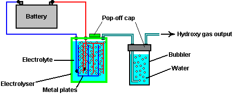
For the purposes of a test of the claims of this patent, it should be sufficient to fill the bubbler with turpentine rather than water, though if possible, it would be good to have an additional bubbler container for the turpentine, in which case, the bubbler with the water should come between the turpentine and the source of the flame. Any tests should be done in an open space, ignited remotely and the person running the test should be well protected behind a robust object. A disadvantage of hydroxy gas is that it requires a very small orifice in the nozzle used for maintaining a continuous flame and the flame temperature is very high indeed. If this patent is correct, then the modified gas produced by the process should be capable of being used in any conventional gas burner.
US Letters Patent 308,276
18th November 1884
Inventor: Henry M. Paine
PROCESS OF MANUFACTURING ILLUMINATING
GAS
To all whom it may concern:
Be it known that I, Henry M. Paine, a citizen of the United States, residing at Newark, in the county of Essex and State of New Jersey, have invented certain new and useful Improvements in the Process of Manufacturing Illuminating-Gas; and I do hereby declare the following to be a full, clear, and exact description of the invention, such as will enable others skilled in the art to which it appertains, to make and use the same, reference being had to the accompanying drawing, and to letters or figures of reference marked thereon, which form a part of this specification.
The present invention relates to the processes for manufacturing illuminating-gas, as explained and set forth here. Up to now, it has always been found necessary to keep the constituent gases of water separated from each other from the point of production to the point of ignition, as hydrogen and oxygen being present in the proper proportions for a complete reunion, form a highly-explosive mixture. Consequently, the two gases have either been preserved in separate holders and only brought together at the point of ignition, or else the hydrogen alone has been saved and the oxygen to support combustion has been drawn from the open air, and the hydrogen gas thus obtained has been carburetted by itself by passing through a liquid hydrocarbon, which imparts luminosity to the flame.
I have discovered that the mixed gases obtained by the decomposition of water through electrolysis can be used with absolute safety if passed through a volatile hydrocarbon; and my invention consists of the new gas thus obtained, and the process described here for treating the gas mixture whereby it is rendered safe for use and storage under the same conditions as prevail in the use of ordinary coal-gas, and is transformed into a highly-luminiferous gas.
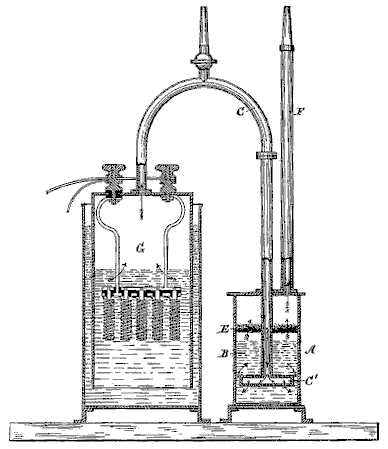
In the accompanying drawing, which shows in sectional elevation, an apparatus adapted to carry out my invention, G is a producer for generating the mixed gases, preferably by the decomposition of water by an electric current. A is a tank partly filled with turpentine, camphene or other hydrocarbon fluid as indicated by B. The two vessels are connected by the pipe C, the end of which terminates below the surface of the turpentine, and has a broad mouthpiece C’, with numerous small perforations, so that the gas rises through the turpentine in fine streams or bubbles in order that it may be brought intimately in contact with the hydrocarbon.
Above the surface of the turpentine there may be a diaphragm E, of wire netting or perforated sheet metal, and above this, a layer of wool or other fibre packed sufficiently tightly to catch all particles of the hydrocarbon fluid which may be mechanically held in suspension, but loose enough to allow free passage of the gases. The pipe F, conducts the mixed gases off directly to the burners or to a holder.
I am aware that the hydrocarbons have been used in the manufacturer of water-gas from steam, and, as stated above, hydrogen gas alone has been carburetted; but I am not aware of any attempt being made to treat the explosive mixed gases in this manner.
Experiments have demonstrated that the amount of turpentine or other volatile hydrocarbon taken up by the gases in this process is very small and that the consumption of the hydrocarbon does not appear to bear any fixed ratio to the volume of the mixed gases passed through it. I do not, however, attempt to explain the action of the hydrocarbon on the gases.
What I claim as my invention and desire to secure by Letters Patent, is -
The process described here of manufacturing gas, which consists in decomposing water by electrolysis and conjointly passing the mixed constituent gases of water thus obtained, through a volatile hydrocarbon, substantially as and for the purpose set forth.
In testimony whereof I affix my signature in presence of two witnesses.
HENRY M. PAINE
Witnesses:
Bennet Osborne, Jr.,
W. E. Redding
Henry Paine’s apparatus would therefor be:
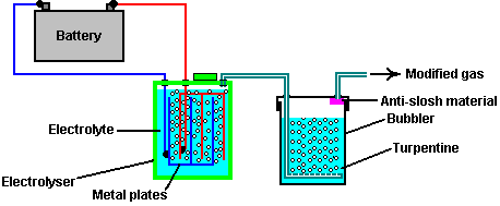
The First
High MPG Carburettor of Charles Pogue
US Patent 642,434 12th
November 1932 Inventor: Charles
N. Pogue
CARBURETTOR
This patent
describes a carburettor design which was able to produce very high mpg figures
using the gasoline available in the
DESCRIPTION
This invention relates to a device for obtaining an intimate contact between a liquid in a vaporous state and a gas, and particularly to such a device which may serve as a carburettor for internal combustion engines.
Carburettors commonly used for supplying a combustible mixture of air and liquid fuel to internal combustion engines, comprise a bowl in which a supply of the fuel is maintained in the liquid phase and a fuel jet which extends from the liquid fuel into a passage through which air is drawn by the suction of the engine cylinders. On the suction, or intake stroke of the cylinders, air is drawn over and around the fuel jet and a charge of liquid fuel is drawn in, broken up and partially vaporised during its passage to the engine cylinders. However, I have found that in such carburettors, a relatively large amount of the atomised liquid fuel is not vaporised and enters the engine cylinder in the form of microscopic droplets. When such a charge is ignited in the engine cylinder, only that portion of the liquid fuel which has been converted into the vaporous (molecular) state, combines with the air to give an explosive mixture. The remaining portion of the liquid fuel which is drawn into the engine cylinders and remains in the form of small droplets, does not explode and impart power to the engine, but burns with a flame and raises the temperature of the engine above that at which the engine operates most efficiently, i.e. 160O to 180O F.
According to this invention, a carburettor for internal combustion engines is provided in which substantially all of the liquid fuel entering the engine cylinder will be in the vapour phase and consequently, capable of combining with the air to form a mixture which will explode and impart a maximum amount of power to the engine, and which will not burn and unduly raise the temperature of the engine.
A mixture of air and liquid fuel in truly vapour phase in the engine cylinder is obtained by vaporising all, or a large portion of the liquid fuel before it is introduced into the intake manifold of the engine. This is preferably done in a vaporising chamber, and the “dry” vaporous fuel is drawn from the top of this chamber into the intake manifold on the intake or suction stroke of the engine. The term “dry” used here refers to the fuel in the vaporous phase which is at least substantially free from droplets of the fuel in the liquid phase, which on ignition would burn rather than explode.
More particularly, the invention comprises a carburettor embodying a vaporising chamber in the bottom of which, a constant body of liquid fuel is maintained, and in the top of which there is always maintained a supply of “dry” vaporised fuel, ready for admission into the intake manifold of the engine. The supply of vaporised liquid fuel is maintained by drawing air through the supply of liquid fuel in the bottom of the vaporising chamber, and by constantly atomising a portion of the liquid fuel so that it may more readily pass into the vapour phase. This is preferably accomplished by a double-acting suction pump operated from the intake manifold, which forces a mixture of the liquid fuel and air against a plate located within the chamber. To obtain a more complete vaporisation of the liquid fuel, the vaporising chamber and the incoming air are preferably heated by the exhaust gasses from the engine. The carburettor also includes means for initially supplying a mixture of air and vaporised fuel so that starting the engine will not be dependent on the existence of a supply of fuel vapours in the vaporising chamber.
The invention will be further described in connection with the accompanying drawings, but this further disclosure and description is to be taken as an exemplification of the invention and the same is not limited thereby except as is pointed out in the claims.
Fig.1 is an elevational view of a carburettor embodying my invention.
Fig.2 is a vertical cross-sectional view through the centre of Fig.1
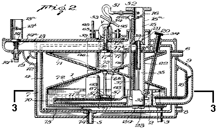
Fig.3 is a horizontal sectional view on line 3--3 of Fig.2.
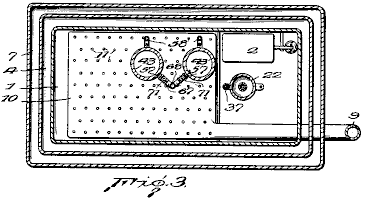
Fig.4 is an enlarged vertical sectional view through one of the pump cylinders and adjacent parts of the carburettor.
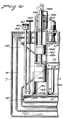
Fig.5 is an enlarged view through the complete double-acting pump and showing the associated distributing valve.
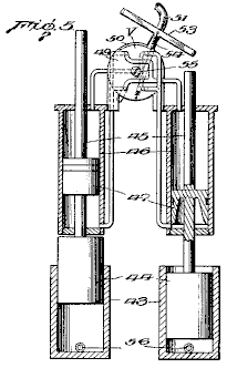
Fig.6 is an enlarged vertical sectional view through the atomising nozzle for supplying a starting charge for the engine.
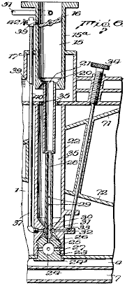
Fig.7 and Fig.8 are detail sectional views of parts 16 and 22 of Fig.6
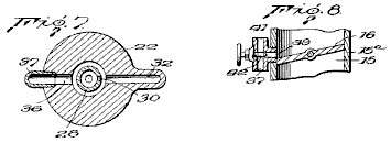
Fig.9 and Fig.10 are detail sectional views showing the inlet and outlet to the cylinders of the atomising pump.
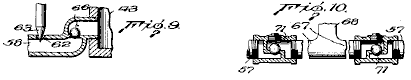
Referring to the drawings, the numeral 1 indicates a combined vaporising chamber and fuel bowl in which liquid fuel is maintained at the level indicated in Fig.1 by a float-valve 2 controlling the flow of liquid fuel through pipe 3 which leads from the vacuum tank or other liquid fuel reservoir.
The vaporising chamber 1 is surrounded by a chamber 4 through which hot exhaust gasses from the engine, enter through pipe 5 located at the bottom of the chamber. These gasses pass around the vaporising chamber 1 and heat the chamber, which accelerates the vaporisation of the liquid fuel. The gasses then pass out through the upper outlet pipe 6.
Chamber 4 for the hot exhaust gasses, is in turn surrounded by chamber 7 into which air for vaporising part of the liquid fuel in chamber 1 enters through a lower intake pipe 8. This air passes upwards through chamber 4 through which the hot exhaust gasses pass, and so the air becomes heated. A portion of the heated air then passes though pipe 9 into an aerator 10, located in the bottom of the vaporising chamber 1 and submerged in the liquid fuel in it. The aerator 10 is comprised of a relatively flat chamber which extends over a substantial portion of the bottom of the chamber and has a large number of small orifices 11 in its upper wall. The heated air entering the aerator passes through the orifices 11 as small bubbles which then pass upwards through the liquid fuel. These bubbles, together with the heat imparted to the vaporising chamber by the hot exhaust gasses, cause a vaporisation of a portion of the liquid fuel.
Another portion of the air from chamber 7 passes through a connection 12 into passage 13, through which air is drawn directly from the atmosphere into the intake manifold. Passage 13 is provided with a valve 14 which is normally held closed by spring 14a, the tension of which may be adjusted by means of the threaded plug 14b. Passage 13 has an upward extension 13a, in which is located a choke valve 13b for assisting in starting the engine. Passage 13 passes through the vaporising chamber 1 and has its inner end communicating with passage 15 via connector 15a which is secured to the intake manifold of the engine. Passage 15 is provided with the usual butterfly valve 16 which controls the amount of fuel admitted to the engine cylinders, and consequently, regulates the speed of the engine.
The portion of passage 13 which passes through the vaporising chamber has an opening 17 normally closed by valve 17a which is held against its seat by spring 17b, the tension of which may be adjusted by a threaded plug 17c. As air is drawn past valve 14 and through passage 13 on the intake or suction stroke of the engine, valve 17a will be lifted from its seat and a portion of the dry fuel vapour from the upper portion of the vaporising chamber will be sucked into passage 13 through opening 17 and mingle with the air in it before entering passage 15.
In order to regulate the amount of air passing from chamber 7 to aerator 10 and into passage 13, pipe 9 and connection 12 are provided with suitable valves 18 and 19 respectively. Valve 18 in pipe 9 is synchronised with butterfly valve 16 in passage 15. Valve 19 is adjustable and preferably synchronised with butterfly valve 16 as shown, but this is not essential.
The bottom of passage 15 is made in the form of a venturi 20 and a nozzle 21 for atomised liquid fuel and air is located at or adjacent to the point of greatest restriction. Nozzle 21 is preferably supplied with fuel from the supply of liquid fuel in the bottom of the vaporising chamber, and to that end, a member 22 is secured within the vaporising chamber by a removable threaded plug 23 having a flanged lower end 24. Plug 22 extends through an opening in the bottom of chamber 1, and is threaded into the bottom of member 22. This causes the bottom wall of chamber 1 to be securely clamped between the lower end of member 22 and flange 24, thus securely retaining member 22 in place.
Plug 23 is provided with a sediment bowl 24 and extending from bowl 24 are several small passages 25 extending laterally, and a central vertical passage 26. The lateral passages 25 register with corresponding passages 27 located in the lower end of member 22 at a level lower than that at which fuel stands in chamber 1, whereby liquid fuel is free to pass into bowl 24.
Vertical passage 26 communicates with a vertical nozzle 28 which terminates within the flaring lower end of nozzle 21. The external diameter of nozzle 26 is less than the interior diameter of the nozzle 21 so that a space is provided between them for the passage of air or and vapour mixtures. Nozzle 26 is also provided with a series of inlets 29, for air or air and vapour mixtures, and a fuel inlet 30. Fuel inlet 30 communicates with a chamber 31 located in the member 22 and surrounding the nozzle 28. Chamber 30 is supplied with liquid fuel by means of a passage 32 which is controlled by a needle valve 33, the stem of which, extends to the outside of the carburettor and is provided with a knurled nut 34 for adjusting purposes.
The upper end of member 22 is made hollow to provide a space 35 surrounding the nozzles 21 and 28. The lower wall of the passage 13 is provided with a series of openings 35a, to allow vapours to enter space 35 through them. The vapours may then pass through inlets 29 into the nozzle 28, and around the upper end of the nozzle 28 into the lower end of nozzle 21.
Extending from chamber 31 at the side opposite passage 32, is a passage 36 which communicates with a conduit 37 which extends upwards through passage 13, and connects through a lateral extension 39, with passage 15 just above the butterfly valve 16. The portion of conduit 37 which extends through passage 13 is provided with an orifice 39 through which air or air and fuel vapour may be drawn into the conduit 37 mingle with and atomise the liquid fuel being drawn through the conduit. To further assist in this atomisation of the liquid fuel passing through conduit 37, the conduit is restricted at 40 just below orifice 39.
The upper end of conduit 37 is in communication with the atmosphere through opening 41 through which air may be drawn directly into the upper portion of the conduit. The proportion of air to combustible vapours coming through conduit 37 is controlled by needle valve 42.
As nozzle 21 enters directly into the lower end of passage 15, suction in the inlet manifold will, in turn, create a suction on nozzle 21 which will cause a mixture of atomised fuel and air to be drawn directly into the intake manifold. This is found to be desirable when starting the engine, particularly in cold weather, when there might not be an adequate supply of vapour in the vaporising chamber , or the mixture of air and vapour passing through passage 13 might be to “lean” to cause a prompt starting of the engine. At such times, closing the choke valve 13b will cause the maximum suction to be exerted on nozzle 21 and the maximum amount of air and atomised fuel to be drawn directly into the intake manifold. After the engine has been started, only a small portion of the combustible air and vapour mixture necessary for proper operation of the engine is drawn through nozzle 21 as the choke valve will then be open to a greater extent and substantially all of the air and vapour mixture necessary for operation of the engine will be drawn through the lower end 20 of passage 15, around nozzle 21.
Conduit 37 extending from fuel chamber 31 to a point above butterfly valve 16 provides an adequate supply of fuel when the engine is idling with vale 16 closed or nearly closed.
The casings forming chambers 1, 4 and 7, will be provided with the necessary openings, to subsequently be closed, so that the various parts may be assembled, and subsequently adjusted or repaired.
The intake stroke of the engine creates a suction in the intake manifold, which in turn causes air to be drawn past spring valve 14 into passage 13 and simultaneously a portion of the dry fuel vapour from the top of vaporising chamber 1 is drawn through opening 17 past valve 17a to mix with the air moving through the passage. This mixture then passes through passage 15 to the intake manifold and engine cylinders.
The drawing of the dry fuel vapour into passage 13 creates a partial vacuum in chamber 1 which causes air to be drawn into chamber 7 around heated chamber 4 from where it passes through connection 12 and valve 19, into passage 13 and through pipe 9 and valve 18 into aerator 10, from which it bubbles up through the liquid fuel in the bottom of chamber 1 to vaporise more liquid fuel.
To assist in maintaining a supply of dry fuel vapour in the upper portion of vaporising chamber 1, the carburettor is provided with means for atomising a portion of the liquid fuel in vaporising chamber 1. This atomising means preferably is comprised of a double-acting pump which is operated by the suction existing in the intake manifold of the engine.
The double-acting pump is comprised of a pair of cylinders 43 which have their lower ends located in the vaporising chamber 1, and each of which has a reciprocating pump piston 44 mounted in it. Pistons 44 have rods 45 extending from their upper ends, passing through cylinders 46 and have pistons 47 mounted on them within the cylinders 46.
Cylinders 46 are connected at each end to a distributing valve V which connects the cylinders alternately to the intake manifold so that the suction in the manifold will cause the two pistons 44 to operate as a double-acting suction pump.
The distributing valve V is comprised of a pair of discs 48 and 49 between which is located a hollow oscillatable chamber 50 which is constantly subjected to the suction existing in the intake manifold through connection 51 having a valve 52 in it. Chamber 50 has a pair of upper openings and a pair of lower openings. These openings are so arranged with respect to the conduits leading to the opposite ends of cylinders 46 that the suction of the engine simultaneously forces one piston 47 upwards while forcing the other one downwards.
The oscillatable chamber 50 has a T-shaped extension 53. The arms of this extension are engaged alternately by the upper ends of the piston rods 45, so as to cause valve V to connect cylinders 46 in sequence to the intake manifold.
Spring 54 causes a quick opening and closing of the ports leading to the cylinders 46 so that at no time will the suction of the engine be exerted on both of the pistons 47. The tension between discs 48 and 49 and the oscillatable chamber 50 may be regulated by screw 55.
The particular form of the distributing valve V is not claimed here so a further description of operation is not necessary. As far as the present invention is concerned, any form of means for imparting movement to pistons 47 may be substituted for the valve V and its associated parts.
The cylinders 43 are each provided with inlets and outlets 56 and 57, each located below the fuel level in chamber 1. The inlets 56 are connected to horizontally and upwardly extending conduits 58 which pass through the carburettor to the outside. The upper ends of these conduits are enlarged at 59 and are provided with a vertically extending slot 60. The enlarged ends 59 are threaded on the inside to accept plugs 61. The position of these plugs with respect to slots 60 determines the amount of air which may pass through the slots 60 and into cylinder 43 on the suction stroke of the pistons 44.
The upper walls of the horizontal portions of conduits 58 have an opening 62 for the passage of liquid fuel from chamber 1. The extent to which liquid fuel may pass through these openings is controlled by needle valves 63, whose stems 64 pass up through and out of the carburettor and terminate in knurled adjusting nuts 65.
The horizontal portion of each conduit 58 is also provided with a check valve 66 (shown in Fig.10) which allows air to be drawn into the cylinders through conduits 58 but prevents liquid fuel from being forced upwards through the conduits on the down stroke of pistons 44.
Outlets 57 connect with horizontal pipes 67 which merge into a single open-ended pipe 68 which extends upwards. The upper open end of this pipe terminates about half way up the height of the vaporising chamber 1 and is provided with a bail 69 which carries a deflecting plate 70 positioned directly over the open end of pipe 68.
The horizontal pipes 67 are provided with check valves 71 which permit the mingled air and fuel to be forced from cylinders 43 by the pistons 44, but which prevent fuel vapour from being drawn from chamber 1 into cylinders 43.
When operating, pistons 44 on the ‘up’ strokes, draw a charge of air and liquid fuel into cylinders 43, and on the ‘down’ stroke, discharge the charge in an atomised condition through pipes 67 and 68, against deflecting plate 70 which further atomises the particles of liquid fuel so that they will readily vaporise. Any portions of the liquid fuel which do not vaporise, drop down into the supply of liquid fuel in the bottom of the vaporising chamber where they are subjected to the vaporising influence of the bubbles of heated air coming from the aerator 10, and may again pass into the cylinders 43.
As previously stated, the vaporised fuel for introduction into the intake manifold of the engine, is taken from the upper portion of the vaporising chamber 1. To ensure that the vapour in this portion of the chamber shall contain no, or substantially no, entrained droplets of liquid fuel, chamber 1 is divided into upper and lower portions by the walls 71 and 72 which converge from all directions to form a central opening 73. With the vaporising chamber thus divided into upper and lower portions which are connected only by the relatively small opening 73, any droplets entrained by the bubbles rising from the aerator 10, will come into contact with the sloping wall 72 and be deflected back into the main body of liquid fuel in the bottom of the chamber. Likewise, the droplets of atomised fuel being forced from the upper end of pipe 68 will, on striking plate 70, be deflected back into the body of liquid fuel and not pass into the upper portion of the chamber.
In order that the speed of operation of the atomising pump may be governed by the speed at which the engine is running, and further, that the amount of air admitted from chamber 7 to the aerator 10, and to passage 13 through connection 12, may be increased as the speed of the engine increases, the valves 18, 19 and 52 and butterfly valve 16 are all connected by a suitable linkage L so that as butterfly valve 16 is opened to increase the speed of the engine, valves 18, 19 and 52 will also be opened.
As shown in Fig.2, the passage of the exhaust gasses from the engine to the heating chamber 4, located between the vaporising chamber and the air chamber 7, is controlled by valve 74. The opening and closing of valve 74 is controlled by a thermostat in accordance with the temperature inside chamber 4, by means of an adjustable metal rod 75 having a high coefficient of expansion, whereby the optimum temperature may be maintained in the vaporising chamber, irrespective of the surrounding temperature.
From the foregoing description, it will be understood that the present invention provides a carburettor for supplying to internal combustion engines, a comingled mixture of air and liquid fuel vapour free from microscopic droplets of liquid fuel which would burn rather than explode in the cylinders and that a supply of such dry vaporised fuel is constantly maintained in the carburettor.
The Second
High MPG Carburettor of Charles Pogue
US Patent 1,997,497 9th
April 1935 Inventor: Charles
N. Pogue
CARBURETTOR
This patent
describes a carburettor design which was able to produce very high mpg figures
using the gasoline available in the
DESCRIPTION
This invention relates to a device for obtaining an intimate contact between a liquid in a truly vaporous state and a gas, and particularly to such a device which may serve as a carburettor for internal combustion engines and is an improvement on the form of device shown in my Patent No. 1,938,497, granted on 5th December 1933.
In carburettors commonly used for supplying a combustible mixture of air and liquid fuel to internal combustion engines, a relatively large amount of the atomised liquid fuel is not vaporised and enters the engine cylinder more or less in the form of microscopic droplets. When such a charge is ignited in the engine cylinder, only that portion of the liquid fuel which has been converted into the vaporous, and consequently molecular state, combines with the air to give an explosive mixture. The remaining portion of the liquid fuel which is drawn into the engine cylinders remains in the form of small droplets and does not explode imparting power to the engine, but instead burns with a flame and raises the engine temperature above that at which the engine operates most efficiently, i.e. from 160O F. to 180O F.
In my earlier patent, there is shown and described a form of carburettor in which the liquid fuel is substantially completely vaporised prior to its introduction into the engine cylinders, and in which, means are provided for maintaining a reverse supply of “dry” vapour available for introduction into the engine cylinder. Such a carburettor has been found superior to the standard type of carburettor referred to above, and to give a better engine performance with far less consumption of fuel.
It is an object of the present invention to provide a carburettor in which the liquid fuel is broken up and prepared in advance of and independent of the suction of the engine and in which a reserve supply of dry vapour will be maintained under pressure, ready for introduction into the engine cylinder at all times. It is also an object of the invention to provide a carburettor in which the dry vapour is heated to a sufficient extent prior to being mixed with the main supply of air which carries it into the engine cylinder, to cause it to expand so that it will be relatively lighter and will become more intimately mixed with the air, prior to explosion in the engine cylinders.
I have found that when the reserve supply of dry vapour is heated and expanded prior to being mixed with the air, a greater proportion of the potential energy of the fuel is obtained and the mixture of air and fuel vapour will explode in the engine cylinders without any apparent burning of the fuel which would result in unduly raising the operating temperature of the engine.
More particularly, the present invention comprises a carburettor in which liquid fuel vapour is passed from a main vaporising chamber under at least a slight pressure, into and through a heated chamber where it is caused to expand and in which droplets of liquid fuel are either vaporised or separated from the vapour , so that the fuel finally introduced into the engine cylinders is in the true vapour phase. The chamber in which the liquid fuel vapour is heated and caused to expand, is preferably comprised of a series of passages through which the vapour and exhaust gases from the engine pass in tortuous paths in such a manner that the exhaust gasses are brought into heat interchange relation with the vapour and give up a part of their heat to the vapour, thus causing heating and expansion of the vapour.
The invention will be further described in connection with the accompanying drawings, but this further disclosure and description is to be taken merely as an exemplification of the invention and the invention is not limited to the embodiment so described.
DESCRIPTION OF THE DRAWINGS
Fig.1 is a vertical cross-sectional view through a carburettor embodying my invention.
Fig.2 is a horizontal sectional view through the main vaporising or atomising chamber, taken on line 2--2 of Fig.1
Fig.3 is a side elevation of the carburettor.
Fig.4 is a detail sectional view of one of the atomising nozzles and its associated parts
Fig.5 is a detail cross-sectional view showing the means for controlling the passage of gasses from the vapour expanding chamber into the intake manifold of the engine.
Fig.6 is a perspective view of one of the valves shown in Fig.5
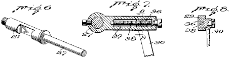
Fig.7 is a cross-sectional view showing means for adjusting the valves shown in Fig.5
Fig.8 is a cross-sectional view on line 8--8 of Fig.7
Referring now to the drawings, the numeral 1 indicates a main vaporising and atomising chamber for the liquid fuel located at the bottom of, and communicating with, a vapour heating and expanding chamber 2.
The vaporising chamber is provided with a perforated false bottom 3 and is normally filled with liquid fuel to the level x. Air enters the space below the false bottom 3 via conduit 4 and passes upwards through perforations 5 in the false bottom and then bubbles up through the liquid fuel, vaporising a portion of it.
To maintain the fuel level x in chamber 1, liquid fuel passes from the usual fuel tank (not shown) through pipe 8 into and through a pair of nozzles 9 which have their outlets located in chamber 1, just above the level of the liquid fuel in it. The pump 7 may be of any approved form but is preferably of the diaphragm type, as such fuel pumps are now standard equipment on most cars.
The nozzles 9 are externally threaded at their lower ends to facilitate their assembly in chamber 1 and to permit them to be removed readily, should cleaning be necessary.
The upper ends of nozzles 9 are surrounded by venturi tubes 10, having a baffle 11, located at their upper ends opposite the outlets of the nozzles. The liquid fuel being forced from the ends of nozzles 9 into the restricted portions of the Venturi tubes, causes a rapid circulation of the air and vapour in the chamber through the tubes 10 and brings the air and vapour into intimate contact with the liquid fuel, with the result that a portion of the liquid fuel is vaporised. The part of the liquid fuel which is not vaporised, strikes the baffles 11 and is further broken up and deflected downwards into the upward-flowing current of air and vapour.
Pump 7 is regulated to supply a greater amount of liquid fuel to the nozzles 9 than will be vaporised. The excess drops into chamber 1 and causes the liquid to be maintained at the indicated level. When the liquid fuel rises above that level, a float valve 12 is lifted, allowing the excess fuel to flow out through overflow pipe 13 into pipe 14 which leads back to pipe 6 on the intake side of pump 7. Such an arrangement allows a large amount of liquid fuel to be circulated by pump 7 without more fuel being withdrawn from the fuel tank than is actually vaporised and consumed in the engine. As the float valve 12 will set upon the end of the outlet pipe 13 as soon as the liquid level drops below the indicated level, there is no danger of vapour passing into pipe 14 and from there into pump 7 and interfere with its normal operation.
The upper end of the vaporising and atomising chamber 1 is open and vapour formed by air bubbling through the liquid fuel in the bottom of the chamber and that formed as the result of atomisation at nozzles 9, pass into the heating and expanding chamber 2. As is clearly shown in Fig.1, chamber 2 comprises a series of tortuous passages 15 and 16 leading from the bottom to the top. The fuel vapour passes through passages 15 and the exhaust gasses of the engine pass through passages 16, a suitable entrance 17 and exit 18 being provided for that purpose.
The vapour passing upwards in a zigzag path through passages 15, will be brought into heat interchange relation with the hot walls of the passages 16 traversed by the hot exhaust gasses. The total length of the passages 15 and 16 is such that a relatively large reserve supply of the liquid fuel is always maintained in chamber 2, and by maintaining the vapour in heat interchange relation with the hot exhaust gasses for a substantial period, the vapour will absorb sufficient heat to cause it to expand, with the result that when it is withdrawn from the top of chamber 2, it will be in the true vapour phase, and due to expansion, relatively light.
Any minute droplets of liquid fuel entrained by the vapour in chamber 1 will precipitate out in the lower passages 15 and flow back into chamber 1, or else be vaporised by the heat absorbed from the exhaust gasses during its passage through chamber 2.
The upper end of vapour passage 15 communicates with openings 19 adjacent to the upper end of a down-draft air tube 20 leading to the intake manifold of the engine. Valves 21 are interposed in openings 19, so that the passage of the vapour through them into the air tube may be controlled. Valves 21 are preferably of the rotary plug type and are controlled as described below.
Suitable means are provided for causing the vapour to be maintained in chamber 2, under a pressure greater than atmospheric, so that when the valves 21 are opened, the vapour will be forced into air tube 20 independent of the engine suction. Such means may comprise an air pump (not shown) for forcing air through pipe 4 into chamber 1 beneath the false bottom 3, but I prefer merely to provide pipe 4 with a funnel-shaped inlet end 22 and placement just behind the usual engine fan 23. This causes air to pass through pipe 4 with sufficient force to maintain the desired pressure in chamber 2, and the air being drawn through the radiator by the fan will be preheated prior to its introduction into chamber 1 and hence will vaporise greater amounts of the liquid fuel. If desired, pipe 4 may be surrounded by an electric or other heater, or exhaust gasses from the engine may be passed around it to further preheat the air passing through it prior to its introduction into the liquid fuel in the bottom of chamber 1.
Air tube 20 is provided with a butterfly throttle valve 24 and a choke valve 24a, as is customary with carburettors used for internal combustion engines. The upper end of air tube 20 extends above chamber 2 a distance sufficient to receive an air filter and/or silencer, if desired.
A low-speed or idling jet 25 has its upper end communicating with the passage through air tube 20 adjacent to the throttling valve 24 and its lower end extending into the liquid fuel in the bottom of chamber 1, for supplying fuel to the engine when the valves are in a position such as to close the passages 19. However, the passage through idling jet 25 is so small that under normal operations, the suction on it is not sufficient to lift fuel from the bottom of chamber 1.
To prevent the engine from backfiring into vapour chamber 2, the ends of the passages 19 are covered with a fine mesh screen 26 which, operating on the principle of the miner’s lamp, will prevent the vapour in chamber 2 from exploding in case of a backfire, but which will not interfere substantially with the passage of the vapour from chamber 2 into air tube 20 when valves 21 are open. Air tube 20 is preferably in the form of a venturi with the greatest restriction being at that point where the openings 19 are located, so that when valves 21 are opened, there will be a pulling force on the vapour caused by the increased velocity of the air at the restricted portion of air tube 20 opposite the openings 19, as well as an expelling force on them due to the pressure in chamber 2.
As shown in Fig.3, the operating mechanism of valves 21 is connected to the operating mechanism for throttle valve 24, so that they are opened and closed simultaneously with the opening and closing of the throttle valve, ensuring that the amount of vapour supplied to the engine will, at all times, be in proportion to the demands placed upon the engine. To that end, each valve 21 has an extension, or operating stem 27, protruding through one of the side walls of the vapour-heating and expanding chamber 2. Packing glands 28 of ordinary construction, surround stems 27 where they pass through the chamber wall, to prevent leakage of vapour at those points.
Operating arms 29 are rigidly secured to the outer ends of stems 27 and extend towards each other. The arms are pivotally and adjustably connected to a pair of links 30 which, at their lower ends are pivotally connected to an operating link 31, which in turn, is pivotally connected to arm 32 which is rigidly secured on an outer extension 33 of the stem of the throttle valve 24. Extension 33 also has rigidly connected to it, arm 34 to which is connected operating link 35 leading from the means for accelerating the engine.
The means for adjusting the connection from the upper ends of links 30 to valve stems 27 of valves 21, so that the amount of vapour delivered from chamber 2 may be regulated to cause the most efficient operation of the particular engine to which the carburettor is attached, comprises angular slides 36, to which the upper ends of links 30 are fastened, and which cannot rotate but can slide in guideways 37 located in arms 29. Slides 36 have threaded holes through which screws 38 pass. Screws 38 are rotatably mounted in arms 29, but are held against longitudinal movement so that when they are rotated, slides 36 will be caused to move along the guideways 37 and change the relative position of links 30 to the valve stems 27, so that a greater or less movement, and consequently, a greater or less opening of the ports 19 will take place when throttle valve 24 is operated.
For safety, and for most efficient operation of the engine, the vapour in chamber 2 should not be heated or expanded beyond a predetermined amount, and in order to control the extent to which the vapour is heated, and consequently, the extent to which it expands, a valve 39 is located in the exhaust passage 16 adjacent to inlet 17. Valve 39 is preferably theromstatically controlled, as for example, by an expanding rod thermostat 40, which extends through chamber 2. However, any other means may be provided for reducing the amount of hot exhaust gasses entering passage 16 when the temperature of the vapour in the chamber reaches or exceeds the optimum.
The carburettor has been described in detail in connection with a down-draft type of carburettor, but it is to be understood that its usefulness is not to be restricted to that particular type of carburettor, and that the manner in which the mixture of air and vapour is introduced into the engine cylinders is immaterial as far as the advantages of the carburettor are concerned.
The term “dry vapour” is used to define the physical condition of the liquid fuel vapour after removal of liquid droplets or the mist which is frequently entrained in what is ordinarily termed a vapour.
From the foregoing description it will be seen that the present invention provides a carburettor in which the breaking up of the liquid fuel for subsequent use is independent of the suction created by the engine, and that after the liquid fuel is broken up, it is maintained under pressure in a heated space for a length of time sufficient to permit all entrained liquid particles to be separated or vaporised and to permit the dry vapour to expand prior to its introduction into and admixture with the main volume of air passing into the engine cylinders.
The Third High
MPG Carburettor of Charles Pogue
US Patent 2,026,798 7th
January 1936 Inventor: Charles
N. Pogue
CARBURETTOR
This patent
describes a carburettor design which was able to produce very high mpg figures
using the gasoline available in the
DESCRIPTION
This invention relates to carburettors suitable for use with internal combustion engines and is an improvement on the carburettors shown in my Patents Nos. 1,938,497, granted on 5th December 1933 and 1,997,497 granted on 9th April 1935.
In my earlier patents, an intimate contact between such as the fuel used for internal combustion engines, and a gas such as air, is obtained by causing the gas to bubble up through a body of the liquid. The vaporised liquid passes into a vapour chamber which preferably is heated, and any liquid droplets are returned to the body of the liquid, with the result that the fuel introduced into the combustion chambers is free of liquid particles , and in the molecular state so that an intimate mixture with the air is obtained to give an explosive mixture from which nearer the maximum energy contained in the liquid fuel is obtained. Moreover, as there are no liquid particles introduced into the combustion chambers, there will be no burning of the fuel and consequently, the temperature of the engine will not be increased above that at which it operates most efficiently.
In my Patent No. 1,997,497, the air which is to bubble up through the body of the liquid fuel is forced into and through the fuel under pressure and the fuel vapour and air pass into a chamber where they are heated and caused to expand. The introduction of the air under pressure and the expansion of the vaporous mixture ensures a sufficient pressure being maintained in the vapour heating and expanding chamber, to cause at least a portion of it to be expelled from it into the intake manifold as soon as the valve controlling the passage to it is opened.
In accordance with the present invention, improved means are provided for maintaining the vaporous mixture in the vapour-heating chamber under a predetermined pressure, and for regulating such pressure so that it will be at the optimum for the particular conditions under which the engine is to operate. Such means preferably comprises a reciprocating pump operated by a vacuum-actuated motor for forcing the vapour into and through the chamber. The pump is provided with a suitable pressure-regulating valve so that when the pressure in the vapour-heating chamber exceeds the predetermined amount, a portion of the vapour mixture will be by-passed from the outlet side to the inlet side of the pump, and so be recirculated.
The invention will be described further in connection with the accompanying drawings, but such further disclosure and description is to be taken merely as an exemplification of the invention, and the invention is not limited to that embodiment of the invention.
DESCRIPTION OF THE DRAWINGS
Fig.1 is a side elevation of a carburettor embodying the invention.

Fig.2 is a plan view of the carburettor
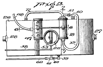
Fig.3 is an enlarged vertical section view.
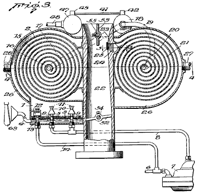
Fig.4 is a transverse sectional view on line 4--4 of Fig.3
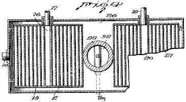
Fig.5 is a detail sectional view on line 5--5 of Fig.3
Fig.6 is a transverse sectional view through the pump and actuating motor, taken on line 6--6 of Fig.2
Fig.7 is a longitudinal sectional view through the pump taken on line 7--7 of Fig.2
Fig.8 is a longitudinal sectional view through a part of the pump cylinder, showing the piston in elevation.
In the drawings, a vaporising and atomising chamber 1 is located at the bottom of the carburettor and has an outlet at its top for the passage of fuel vapour and air into a primary vapour-heating chamber 2.
The vaporising chamber 1 is provided with a perforated false bottom 3 and is normally filled with liquid fuel to the level indicated in Fig.1. Air is introduced via conduit 4 into the space below the false bottom 3, and then through the perforations 5 in the false bottom which breaks it into a myriad of fine bubbles, which pass upwards through the liquid fuel above the false bottom.
Liquid fuel for maintaining the level indicated in chamber 1 passes from the usual fuel tank (not shown) through pipe 6, and is forced by pump 7 through pipe 8 through a pair of nozzles 9 having their outlets located in chamber 1, just above the level of the liquid fuel in it. Pump 7 may be of any approved form but is preferably of the diaphragm type, as such fuel pumps are now standard equipment on most cars.
The nozzles 9 are externally threaded at their lower ends to facilitate their assembly in chamber 1 and to permit them to be readily removed should cleaning become necessary.
The upper ends of nozzles 9 are surrounded by venturi tubes 10 having baffles 11 located at their upper ends opposite the outlets of the nozzles, as is shown and described in detail in my Patent No. 1,997,497. The liquid fuel being forced from the ends of nozzles 9 into the restricted portions of the venturi tubes, causes a rapid circulation of the air and vapour in the chamber through tubes 10 and brings the air and vapour into intimate contact with the liquid fuel, with the result that a portion of the liquid fuel is vaporised. Unvaporised portions of the liquid fuel strike the baffles 11 and are thereby further broken up and deflected downwards into the upward-flowing current of air and vapour.
Pump 7 is regulated to supply a greater amount of liquid fuel to nozzles 9 than will be vaporised. The excess liquid fuel drops into chamber 1 which causes the liquid there to be maintained at the indicated level. When the liquid fuel rises above that level, float valve 12 opens and the excess fuel flows through overflow pipe 13 into pipe 14 which leads back to pipe 6 on the intake side of pump 7. Such an arrangement permits a large amount of liquid fuel to be circulated by pump 7 without more fuel being withdrawn from the fuel tank than is actually vaporised and consumed by the engine. As float valve 12 will set upon the end of the outlet pipe 13 as soon as the liquid level drops below the indicated level, there is no danger of vapour passing into pipe 14 and thence into pump 7 to interfere with its normal operation.
The amount of liquid fuel vaporised by nozzles 9 and by the passage of air through the body of liquid, is sufficient to provide a suitably enriched vaporous mixture for introducing into the passage leading to the intake manifold of the engine, through which the main volume of air passes.
Vapour formed by air bubbling through the liquid fuel in the bottom of chamber 1 and that formed by the atomisation at the nozzles 9, pass from the top of that chamber into the primary heating chamber 2. As is clearly shown in Fig.1, chamber 2 comprises a relatively long spiral passage 15 through which the vaporous mixture gradually passes inwards to a central outlet 16 to which is connected a conduit 17 leading to a reciprocating pump 18 which forces the vaporous mixture under pressure into conduit 19 leading to a central inlet 20 of a secondary heating chamber 21, which like the primary heating chamber, comprises a relatively long spiral. The vaporous mixture gradually passes outwards through the spiral chamber 21 and enters a downdraft air tube 22, leading to the intake manifold of the engine, through an outlet 23 controlled by a rotary plug valve 24.
To prevent the engine from backfiring into vapour chamber 2, the ends of passage 19 are covered with a fine mesh screen 25, which, operating on the principle of a miner’s lamp, will prevent the vapour in chamber 2 from exploding in case of a backfire, but will not interfere substantially with the passage of the vapour from chamber 21 into air tube 22 when valve 24 is open.
The air tube 22 is preferably in the form of a venturi with the greatest constriction being at that point where outlet 23 is located, so that when valve 24 is opened, there will be a pulling force on the vaporous mixture due to the increased velocity of the air at the restricted portion of the air tube opposite outlet 23, as well as an expelling force on it due to the pressure maintained in chamber 21 by pump 18.
Both the primary and secondary spiral heating chambers 15 and 21, and the central portion of air tube 22 are enclosed by a casing 26 having an inlet 27 and an outlet 28 for a suitable heating medium such as the gasses coming from the exhaust manifold.
Pump 18, used to force the vaporous mixture from primary heating chamber 2 into and through the secondary chamber 21, includes a working chamber 29 for hollow piston 30, provided with an inlet 31 controlled by valve 32, and an outlet 33 controlled by a valve 34. The end of the working chamber 29 to which is connected conduit 17, which conducts the vaporous mixture from primary heating chamber 2, has an inlet valve 35, and the opposite end of the working chamber has an outlet 36 controlled by valve 37 positioned in an auxiliary chamber 38, to which is connected outlet pipe 19 which conducts the vaporous mixture under pressure to the secondary heating chamber 21. Each of the valves 32, 34, 35 and 37 is of the one-way type. They are shown as being gravity-actuated flap valves, but it will be understood that spring-loaded or other types of one-way valves may be used if desired.
One side of piston 30 is formed with a gear rack 39 which is received in a groove 39a of the wall forming the cylinder of the pump. The gear rack 39 engages with an actuating spur gear 40 carried on one end of shaft 41 and operating in a housing 42 formed on the pump cylinder. The other end of shaft 41 carries a spur gear 43, which engages and is operated by a gear rack 44 carried on a piston 46 of a double-acting motor 47. The particular construction of the double-acting motor 47 is not material, and it may be of a vacuum type commonly used for operating windscreen wipers on cars, in which case a flexible hose 48 would be connected with the intake manifold of the engine to provide the necessary vacuum for operating the piston 45.
Under the influence of the double-acting motor 47, the piston 30 of the pump has a reciprocatory movement in the working chamber 29. Movement of the piston towards the left in Fig.7 tends to compress the vaporous mixture in the working chamber between the end of the piston and the inlet from pipe 17, and causes valve 35 to be forced tightly against the inlet opening. In a like manner, valves 32 and 34 are forced open and the vaporous mixture in that portion of the working chamber is forced through the inlet 31 in the end of the piston 30, into the interior of the piston, where it displaces the vaporous mixture there and forces it into the space between the right-hand end of the piston and the right-hand end of the working chamber. The passage of the vaporous mixture into the right-hand end of the working chamber is supplemented by the partial vacuum created there when the piston moves to the left. During such movement of the piston, valve 37 is maintained closed and prevents any sucking back of the vaporous mixture from the secondary heating chamber 21.
When motor 47 reverses, piston 30 moves to the right and the vaporous mixture in the right-hand end of the working chamber is forced past valve 37 through pipe 19 into the secondary heating chamber 21. At the same time, a vacuum is created behind piston 30 which results in the left-hand end of the working chamber being filled again with the vaporous mixture from the primary heating chamber 2.
As the operation of pump 47 varies in accordance with the suction created in the intake manifold, it should be regulated so that the vaporous mixture is pumped into the secondary heating chamber at a rate sufficient to maintain a greater pressure there than is needed. In order that the pressure in the working chamber may at all times be maintained at the optimum, a pipe 50 having an adjustable pressure-regulating valve 51 is connected between the inlet and outlet pipes 17 and 19. Valve 51 will permit a portion of the vaporous mixture discharged from the pump to be bypassed to inlet 17 so that a pressure predetermined by the seating of valve 51 will at all times be maintained in the second heating chamber 21.
Air tube 22 is provided with a butterfly throttle valve 52 and a choke valve 53, as is usual with carburettors adapted for use with internal combustion engines. Operating stems 54, 55 and 56 for valves 52, 53 and 24 respectively, extend through casing 26. An operating arm 57 is rigidly secured to the outer end of stem 55 and is connected to a rod 58 which extends to the dashboard of the car, or some other place convenient to the driver. The outer end of stem 56 of valve 24 which controls outlet 23 from the secondary heating chamber 21 has one end of an operating arm 59 fixed securely to it. The other end is pivotally connected to link 60 which extends downwards and pivotally connects to one end of a bell crank lever 61, rigidly attached to the end of stem 54 of throttle valve 52. The other end of the bell crank lever is connected to an operating rod 62 which, like rod 58, extends to a place convenient to the driver. Valves 24 and 52 are connected for simultaneous operation so that when the throttle valve 52 is opened to increase the speed of the engine, valve 24 will also be opened to admit a larger amount of the heated vaporous mixture from the secondary heating chamber 21.
While the suction created by pump 18 ordinarily will create a sufficient vacuum in the primary heating chamber 2 to cause air to be drawn into and upwards through the body of liquid fuel in the bottom of vaporising chamber 1, in some instances it may be desirable to provide supplemental means for forcing the air into and up through the liquid, and in such cases an auxiliary pump may be provided for that purpose, or the air conduit 4 may be provided with a funnel-shaped intake which is positioned behind the engine fan 63 which is customarily placed behind the engine radiator.
The foregoing description has been given in connection with a downdraft type of carburettor, but it is to be understood that the invention is not limited to use with such type of carburettors and that the manner in which the mixture of air and vapour is introduced into the engine cylinders is immaterial as far as the advantages of the carburettor are concerned.
Before the carburettor is put into use, the pressure-regulating valve 51 in the bypass pipe 50 will be adjusted so that the pressure best suited to the conditions under which the engine is to be operated, will be maintained in the secondary heating chamber 21. When valve 51 has thus been set and the engine started, pump 18 will create a partial vacuum in the primary heating chamber 2 and cause air to be drawn through conduit 4 to bubble upwards through the liquid fuel in the bottom of the vaporising and atomising chamber 1 with the resulting vaporisation of a part of the liquid fuel. At the same time, pump 7 will be set into operation and liquid fuel will be pumped from the fuel tank through the nozzles 9 which results in an additional amount of the fuel being vaporised. The vapour resulting from such atomisation of the liquid fuel and the passage of air through the body of the liquid, will pass into and through spiral chamber 1 where they will be heated by the products of combustion in the surrounding chamber formed by casing 26. The fuel vapour and air will gradually pass inwards through outlet 16 and through conduit 17 to pump 18 which will force them into the secondary heating chamber 21 in which they will be maintained at the predetermined pressure by the pressure-regulating valve 51. The vaporous mixture is further heated in chamber 21 and passes spirally outward to the valve-controlled outlet 23 which opens into air tube 22 which conducts the main volume of air to the intake manifold of the engine.
The heating of the vaporous mixture in the heating chambers 2 and 21, tends to cause them to expand, but expansion in chamber 21 is prevented due to the pressure regulating valve 51. However, as soon as the heated vaporous mixture passes valve 24 and is introduced into the air flowing through intake tube 22, it is free to expand and thereby become relatively light so that a more intimate mixture with the air is obtained prior to the mixture being exploded in the engine cylinders. Thus it will be seen that the present invention not only provides means wherein the vaporous mixture from heating chamber 21 is forced into the air passing through air tube 22 by a positive force, but it is also heated to such an extent that after it leaves chamber 21 it will expand to such an extent as to have a density less than it would if introduced directly from the vaporising and atomising chamber 1 into the air tube 22.
The majority of the liquid particles entrained by the vaporous mixture leaving chamber 1 will be separated in the first half of the outermost spiral of the primary heating chamber 2 and drained back into the body of liquid fuel in tank 1. Any liquid particles which are not thus separated, will be carried on with the vaporous mixture and due to the circulation of that mixture and the application of heat, will be vaporised before the vaporous mixture is introduced into the air tube 22 from the secondary heating chamber 21. Thus only “dry” vapour is introduced into the engine cylinders and any burning in the engine cylinders of liquid particles of the fuel, which would tend to raise the engine temperature above its most efficient level, is avoided.
While the fullest benefits of the invention are obtained by using both a primary and secondary heating chamber, the primary heating chamber may, if desired, be eliminated and the vaporous mixture pumped directly from the vaporising and atomising chamber 1 into the spiral heating chamber 21.
From the foregoing description it will be seen that the present invention provides an improvement over the carburettor disclosed in my Patent No. 1,997,497, in that it is possible to maintain the vaporous mixture in the heating chamber 21 under a predetermined pressure, and that as soon as the vaporous mixture is introduced into the main supply of air passing to the intake manifold of the engine, it will expand and reach a density at which it will form a more intimate mixture with the air. Furthermore, the introduction of the vaporous mixture into the air stream in the tube 22, causes a certain amount of turbulence which also tends to give a more intimate mixture of vapour molecules with the air.
The High
MPG Carburettor of Ivor Newberry
US Patent 2,218,922
22nd October 1940
Inventor: Ivor B. Newberry
VAPORIZER FOR COMBUSTION ENGINES
This patent
describes a carburettor design which was able to produce very high mpg figures
using the gasoline available in the
DESCRIPTION
This invention relates to fuel vaporising devices for combustion engines and more particularly, is concerned with improvements in devices of the kind where provision is made for using the exhaust gasses of the engines as a heating medium to aid in the vaporisation of the fuel.
One object of the invention is to provide a device which will condition the fuel in such a manner that its potential energy may be fully utilised, thereby ensuring better engine performance and a saving in fuel consumption, and preventing the formation of carbon deposits in the cylinders of the engine and the production of carbon monoxide and other objectionable gasses.
A further object is to provide a device which is so designed that the fuel is delivered to the cylinders of the engine in a highly vaporised, dry and expanded state, this object contemplating a device which is available as an exhaust box in which the vaporisation and expansion of the liquid components is effected at sub-atmospheric pressures and prior to their being mixed with the air component.
A still further object is to provide a device which will condition the components of the fuel in such a manner that they be uniformly and intimately mixed without the use of a carburettor.
A still further object is to provide a device which will enable the use of various inferior and inexpensive grades of fuel.
DESCRIPTION OF THE DRAWINGS
Fig.1 is an elevational view of the device as applied to the engine of a motor vehicle.
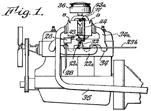
Fig.2 is an enlarged view of the device, partially in elevation and partially in section.
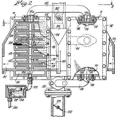
Fig.3 is a section taken along line 3--3 of Fig.2
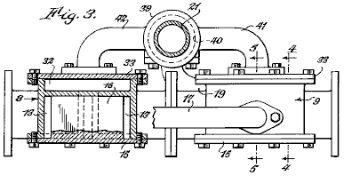
Fig.4 is a section taken along line 4--4 of Fig.3
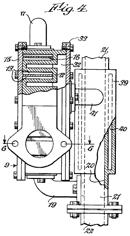
Fig.5 is a fragmentary section taken along line 5--5 of Fig.3
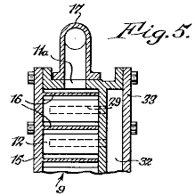
Fig.6 is a section taken along line 6--6 of Fig.4
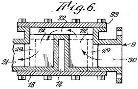
DESCRIPTION
The device as illustrated, includes similar casings 8 and 9 which are secured together as a unit and which are formed to provide vaporising chambers 10 and 11, respectively, it being understood that the number of casings may be varied. Two series of ribs 12 are formed in each of the vaporising chambers, the ribs of each series being spaced from one another so as to provide branch passages 13 and being spaced from the ribs of the adjacent series to provide main passages 14 with which the branch passages communicate.
The vaporising chambers are closed by cover plates 15. The cover plates carry baffles 16 which are supported in the spaces between the ribs 12. The baffles extend across the main passages 14 and into, but short of the ends of the branch passages 13 to provide tortuous paths. Outlet 10a of chamber 10 is connected by conduit 17 to inlet 11a of chamber 11. Outlet 18 of chamber 11, is connected by conduit 19 with mixing chamber 20 which is located at the lower end of pipe 21 which in turn is connected to and extension 22 of the intake manifold 22a of the engine. Extension 22 contains a valve 23 which is connected by a lever 23a (Fig.1) and rod 23b to a conventional throttle (not shown).
The liquid fuel is introduced into the vaporising chamber 10 through nozzle 24 which is connected by pipe 25 to a reservoir 26 in which the fuel level is maintained by float-controlled valve 27, the fuel being supplied to the reservoir through pipe 28.
In accordance with the invention, ribs 12 are hollow, each being formed to provide a cell 29. The cells in one series of ribs open at one side into an inlet chamber 30, while the cells of the companion series open at one side into an outlet chamber 31. The cells of both series of ribs open at their backs into a connecting chamber 32 which is located behind the ribs and which is closed by a cover plate 33. Casings 8 and 9 are arranged end-to-end so that the outlet chamber of 9 communicates with the inlet chamber of 8, the gasses from the exhaust manifold 34 being introduced into the inlet chamber of casing 9 through extension 34a. The exhaust gasses enter the series of cells at the right hand side of the casing, pass through the cells into the connecting chamber at the rear and then enter the inlet chamber of casing 8. They pass successively through the two series of cells and enter exhaust pipe 35. The exhaust gasses leave the outlet chamber 31, and the path along which they travel is clearly shown by the arrows in Fig.6. As the gasses pass through casings 8 and 9, their speed is reduced to such a degree that an exhaust box (muffler) or other silencing device is rendered unnecessary.
It will be apparent that when the engine is operating a normal temperature, the liquid fuel introduced into chamber 10 will be vaporised immediately by contact with the hot walls of ribs 12. The vapour thus produced is divided into two streams, one of which is caused to enter each of the branch passages at one side of the casing and the other is caused to enter each of the branch passages at the opposite side of the casing. The two streams of vapour merge as they pass around the final baffle and enter conduit 17, but are again divided and heated in a similar manner as they flow through casing 9. Each of the vapour streams is constantly in contact with the highly heated walls of ribs 12. This passage of the vapour through the casings causes the vapour to be heated to such a degree that a dry highly-vaporised gas is produced. In this connection, it will be noted that the vaporising chambers are maintained under a vacuum and that vaporisation is effected in the absence of air. Conversion of the liquid into highly expanded vapour is thus ensured. The flow of the exhaust gasses through casings 8 and 9 is in the opposite direction to the flow of the vapour. The vapour is heated in stages and is introduced into chamber 20 at its highest temperature.
The air which is mixed with the fuel vapour, enters pipe 21 after passing through a conventional filter 36, the amount of air being regulated by valve 37. The invention also contemplates the heating of the air prior to its entry into mixing chamber 20. To this end, a jacket 39 is formed around pipe 21. The jacket has a chamber 40 which communicates with chamber 32 of casing 9 through inlet pipe 41 and with the corresponding chamber of casing 8 through outlet pipe 42. A portion of the exhaust gasses is thus caused to pass through chamber 40 to heat the air as it passes through conduit 21 on its way to the mixing chamber. Valve 37 is connected to valve 23 by arms 43 and 43a and link 44 so that the volume of air admitted to the mixing chamber is increased proportionately as the volume of vapour is increased. As the fuel vapour and air are both heated to a high temperature and are in a highly expanded state when they enter the mixing chamber, they readily unite to provide a uniform mixture, the use of a carburettor or similar device for this purpose being unnecessary.
From the foregoing it will be apparent that the components of the fuel mixture are separately heated prior to their entry into mixing chamber 20. As the vapour which is produced is dry (containing no droplets of liquid fuel) and highly expanded, complete combustion is ensured. The potential energy represented by the vapour may thus be fully utilised, thereby ensuring better engine performance and a saving in fuel consumption. At the same time, the formation of carbon deposits in the combustion chambers and the production of carbon monoxide and other objectionable exhaust gasses is prevented. The device has the further advantage that, owing to the high temperature to which the fuel is heated prior to its admission into the combustion chambers, various inferior and inexpensive grades of fuel may be used with satisfactory results.
The High
MPG Carburettor of Robert Shelton
US Patent 2,982,528
2nd May 1940 Inventor: Robert S. Shelton
VAPOUR FUEL SYSTEM
This patent
describes a carburettor design which was able to produce very high mpg figures
using the gasoline available in the
DESCRIPTION
This invention relates to improvements in vapour fuel systems which are to be used for internal combustion engines.
An object of this invention is to provide a vapour fuel system which will provide a great saving in fuel since approximately eight times the mileage that is obtained by the conventional combustion engine, is provided by the use of this system.
Another object of the invention is to provide a vapour fuel system which is provided with a reservoir to contain liquid fuel which is heated to provide vapour from which the internal combustion engine will operate.
With the above and other objects and advantages in view, the invention consists of the novel details of construction, arrangement and combination of parts more fully described below, claimed and illustrated in the accompanying drawings.
DESCRIPTION
OF THE DRAWINGS
Fig.1 is an elevational view of a vapour fuel system embodying the invention.
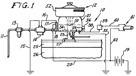
Fig.2 is an enlarged view, partly in section, showing the carburettor forming part of the system shown in Fig.1.
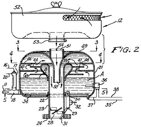
Fig.3 is a transverse sectional view on line 3--3 of Fig.2
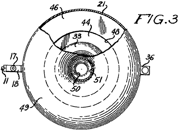
Fig.4 is a transverse sectional view on line 4--4 of Fig.2
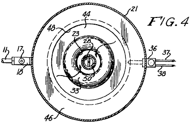
Fig.5 is a transverse sectional view on line 5--5 of Fig.2
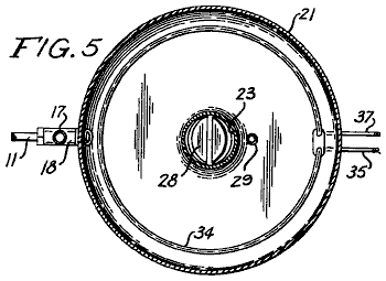
The reference numbers used in the drawings always refer to the same item in each of the drawings. The vapour fuel system 10 includes a conduit 11 which is connected to the fuel tank at one end and to a carburettor 12 at the opposite end. In conduit 11 there is a fuel filter 13 and an electric fuel pump 14. Wire 15 grounds the pump and wire 16 connects the pump to a fuel gauge 18 on which is mounted a switch 17 which is connected to a battery 19 of the engine by wire 20.
The fuel gauge/switch is of conventional construction and is of the type disclosed in US Patents No. 2,894,093, No. 2,825,895 and No. 2,749,401. The switch is so constructed that a float in the liquid in the gauge, opens a pair of contacts when the liquid rises and this cuts off the electric pump 14. As the float lowers due to the consumption of the liquid fuel in the body, the float falls, closing the contacts and starting pump 14 which replenishes the liquid fuel in the body.
Carburettor 12 includes a dome-shaped circular bowl or reservoir 21 which is provided with a centrally located flanged opening 22 whereby the reservoir 21 is mounted on a tubular throat 23. An apratured collar 24 on the lower end of throat 23 is positioned on the intake manifold 25 of an internal combustion engine 26 and fastenings 27 secure the collar to the manifold in a fixed position.
A vapour control butterfly valve 28 is pivotally mounted in the lower end of throat 23 and valve 28 controls the entrance of the vapour into the engine and so controls its speed.
A fuel pump 29, having an inlet 30, is mounted in the bottom of the reservoir 21 so that the inlet 30 communicates with the interior of the reservoir. A spurt or feed pipe 31 connected to pump 29 extends into throat 23 so that by means of a linkage 32 which is connected to pump 29 and to a linkage for control valve 28 and the foot throttle of the engine, raw fuel may be forced into throat 23 to start the engine when it is cold.
The upper end of throat 23 is turned over upon itself to provide a bulbous hollow portion 33 within reservoir 21. An immersion heater 34 is positioned in the bottom of the reservoir and wire 35 grounds the heater. A thermostat 36 is mounted in the wall of the reservoir and extends into it. Wire 37 connects the thermostat to heater 34 and wire 38 connects the thermostat to the thermostat control 39. Wire 40 connects the control to the ignition switch 41 which in turn is connected to battery 19 via wires 20 and 42.
A pair of relatively spaced parallel perforated baffle plates 43 and 44, are connected to the bulbous portion 33 on the upper end of throat 23, and a second pair of perforated baffle plates 45 and 46 extend inwards from the wall of reservoir 21 parallel to each other and parallel to baffle plates 43 and 44.
The baffle plates are arranged in staggered relation to each other so that baffle plate 45 is between baffle plates 43 and 44 and baffle plate 46 extends over baffle plate 44.
Baffle plate 45 has a central opening 47 and baffle plate 46 has a central opening 48 which has a greater diameter than opening 47. The domed top 49 of reservoir 21, extends into a tubular air intake 50 which extends downwards into throat 23 and a mounting ring 51 is positioned on the exterior of the domed top, vertically aligned with intake 50. An air filter 52 is mounted on the mounting ring 51 by a coupling 53 as is the usual procedure, and a spider 54 is mounted in the upper end of mounting ring 51 to break up the air as it enters ring 51 from air filter 52.
In operation, with carburettor 12 mounted on the internal combustion engine instead of a conventional carburettor, ignition switch 41 is turned on. Current from battery 19 will cause pump 14 to move liquid fuel into reservoir 21 until float switch 18 cuts the pump off when the liquid fuel A has reached level B in the reservoir. The control 39 is adjusted so that thermostat 36 will operate heater 34 until the liquid fuel has reached a temperature of 1050 F at which time heater 34 will be cut off. When the liquid fuel has reached the proper temperature, vapour will be available to follow the course indicated by the arrows in Fig.2.
The engine is then started and if the foot control is actuated, pump 29 will cause raw liquid fuel to enter the intake manifold 25 until the vapour from the carburettor is drawn into the manifold to cause the engine to operate. As the fuel is consumed, pump 14 will again be operated and heater 34 will be operated by thermostat 36. Thus, the operation as described will continue as long as the engine is operating and the ignition switch 41 is turned on. Reservoir 21 will hold from 4 to 6 pints (2 to 4 litres) of liquid fuel and since only the vapour from the heated fuel will cause the carburettor 12 to run the engine, the engine will operate for a long time before more fuel is drawn into reservoir 21.
Baffles 43, 44, 45 and 46 are arranged in staggered relation to prevent splashing of the liquid fuel within the carburettor. The level B of the fuel in reservoir 21 is maintained constant by switch 18 and with all elements properly sealed, the vapour fuel system 10 will operate the engine efficiently.
Valve 28 controlling the entrance of vapour into intake manifold 25, controls the speed of the engine in the same manner as the control valve in a conventional carburettor.
There has thus been described a vapour fuel system embodying the invention and it is believed that the structure and operation of it will be apparent to those skilled in the art. It is also to be understood that changes in the minor details of construction, arrangement and combination of parts may be resorted to provided that they fall within the spirit of the invention.
The High
MPG Carburettor of Harold Schwartz
US Patent 3,294,381 27th
December 1966 Inventor: Harold
Schwartz
CARBURETTOR
This patent
describes a carburettor design which was able to produce very high mpg figures
using the gasoline available in the
DESCRIPTION
This invention relates to a carburettor construction. An object of the present invention is to provide a carburettor in which the fuel is treated by the hot exhaust fumes of an engine before being combined with air and being fed into the engine.
Another object of the invention is to provide a carburettor as characterised above, which circulates the fume-laden fuel in a manner to free it of inordinately large globules of fuel, thereby insuring that only finely divided and pre-heated fuel of mist-like consistency is fed to the intake manifold of the engine.
The present carburettor, when used for feeding the six-cylinder engine of a popular car, improved the miles per gallon performance under normal driving conditions using a common grade of fuel, by over 200%. This increased efficiency was achieved from the pre-heating of the fuel and keeping it under low pressure imposed by suction applied to the carburettor for the purpose of maintaining the level of fuel during operation of the engine. This low pressure in the carburettor causes increased vaporisation of the fuel in the carburettor and raises the efficiency of operation.
This invention also has for its objects; to provide a carburettor which is positive in operation, convenient to use, easily installed in its working position, easily removed from the engine, economical to manufacture, of relatively simple design and of general superiority and serviceability.
The invention also comprises novel details of construction and novel combinations and arrangements of parts, which will appear more fully in the course of the following description and which is based on the accompanying drawings. However, the drawings and following description merely describes one embodiment of the present invention, and are only given as an illustration or example.
DESCRIPTION
OF THE DRAWINGS
In the drawings, all reference numbers apply to the same parts in each drawing.
Fig.1 is a partly broken plan view of a carburettor constructed in accordance with the present invention, shown with a fuel supply, feeding and return system.
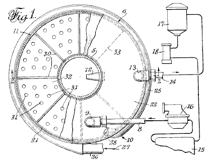
Fig.2 is a vertical sectional view of the carburettor taken on the plane of line 2--2 in Fig.1
Fig.3 is a partial side elevation and partial sectional view of the carburettor, showing additional structural details
The carburettor is preferably mounted on the usual downdraft air tube 5 which receives a flow of air through the air filter. Tube 5 is provided with a throttle or butterfly valve which controls the flow and incorporates a flow-increasing venturi passage. These common features of the fuel feed to the engine intake manifold are not shown since these features are well known and they are also disclosed in my pending Patent application Serial No. 182,420 now abandoned. The present carburettor embodies improvements over the disclosure of the earlier application.
The present carburettor comprises a housing 6 mounted on air tube 5, and designed to hold a shallow pool of fuel 7, a fuel inlet 8 terminating in a spray nozzle 9, an exhaust gas manifold 10 to conduct heated exhaust gasses for discharge into the spray of fuel coming out of nozzle 9 and for heating the pool of fuel 7 underneath it. Means 11 to scrub the fuel-fumes mixture to eliminate large droplets of fuel from the mixture (the droplets fall into pool 7 underneath), a nozzle tube 12 to receive the scrubbed mixture and to pass the mixture under venturi action into air tube 5 where it is combined with air and made ready for injection into the intake manifold of the engine. Pickup pipe 13 is connected to an outlet 14 for drawing excess fuel from pool 7 during operation of the carburettor.
The system connected to the carburettor is shown in Fig.1, and comprises a fuel tank 15, a generally conventional fuel pump 16 for drawing fuel from the tank and directing it to inlet 8, a fuel filter 17, and a pump 18 connected in series between the fuel tank and outlet 14 to place pipe 13 under suction and to draw excess fuel from the carburettor back to tank 15 for re-circulation to inlet 8.
Carburettor housing 6 may be circular, as shown and quite flat compared to its diameter, so as to have a large flat bottom 20 which, with the cylindrical wall 21, holds the fuel pool 7. Cover 22 encloses the top of the housing. The bottom 20 and cover 22 have aligned central openings through which the downdraft tube 5 extends, this pipe forming the interior of the housing, creating an annular inner space 23.
The fuel inlet 8 is attached to cover 22 by a removable connection. Spray nozzle 9 extends through the cover. While the drawing shows spray-emitting holes 24 arranged to provide a spray around nozzle 7, the nozzle may be formed so that the spray is directional as desired to achieve the most efficient interengagement of the sprayed fuel with the heating gasses supplied by the manifold 10.
The manifold is shown as a pipe 25 which has and end 26 extending from the conventional heat riser chamber (not shown) of the engine, the arrow 27 indicating exhaust gas flow into pipe 25. The pipe may encircle the lower portion of the housing 6, to heat the pool of fuel 7 by transfer of heat through the wall of the housing. The manifold pipe is shown with a discharge end 28 which extends into the housing in an inward and upward direction towards nozzle 9 so that the exhaust gasses flowing in the pipe intermingle with the sprayed fuel and heat it as it leaves the nozzle.
The fuel-scrubbing means 11 is shown as a curved chamber 29 located inside housing 6, provided with a series of baffle walls 30 which cause the fumes-heated fuel mist to follow a winding path and intercept the heavier droplets of fuel which then run down the faces of the baffle walls, through openings 31 in the bottom wall 32 of scrubbing chamber 29 into the interior space 23 of housing 6 above the level of the fuel pool 7.
Pickup pipe 13 is also shown as carried by housing cover 22 and may be adjusted so that its lower open end is so spaced from the housing bottom 20 as to regulate the depth of pool 7, which is preferably below the bottom wall 32 of the scrubbing chamber 29. Since this pipe is subject to the suction of pump 18 through outlet 14 and filter 17, the level of pool 7 is maintained by excess fuel being returned to tank 15 by pump 16.
It will be seen that the surface of pool 7 is subject not only to the venturi action in tube 5, but also to the suction of pump 18 as it draws excess fuel back to fuel tank 15. Thus, the surface of the pool is under somewhat less than atmospheric pressure which increases the rate of vaporisation from the pool surface, the resulting vapour combining with the flow from the scrubbing chamber to the downdraft tube 5..
While this description has illustrated what is now contemplated to be the best mode of carrying out the invention, the construction is, of course, subject to modification without departing from the spirit and scope of the invention. Therefore, it is not desired to restrict the invention to the particular form of construction illustrated and described, but to cover all modifications which may fall within its scope.
The High
MPG Carburettor of Oliver Tucker
US Patent 3,653,643
4th April 1972
Inventor: Oliver M. Tucker
CARBURETTOR
This patent
describes a carburettor design which was able to produce very high mpg figures
using the gasoline available in the
ABSTRACT
A carburettor including a housing having a fluid reservoir in the bottom, an air inlet at the top of the housing, a delivery pipe coaxially mounted within the housing and terminating short of the top of the housing, and a porous vaporising filter substantially filling the reservoir. A baffle is concentrically mounted within the housing and extends partially into the vaporising filter in the reservoir to deflect the incoming air through the filter. The level of liquid fuel in the reservoir is kept above the bottom of the baffle, so that air entering the carburettor through the inlet must pass through the liquid fuel and vaporising filter in the reservoir before discharge through the outlet. A secondary air inlet is provided in the top of the housing for controlling the fuel air ratio of the vaporised fuel passing into the delivery pipe.
BACKGROUND
OF THE INVENTION
It is generally well known that liquid fuel must be vaporised in order to obtain complete combustion. Incomplete combustion of fuel in internal combustion engines is a major cause of atmospheric pollution. In a typical automotive carburettor, the liquid fuel is atomised and injected into the air stream in a manifold of approximately 3.14 square inches in cross-sectional area. In an eight cylinder 283 cubic inch engine running at approximately 2,400 rpm requires 340,000 cubic inches of air per minute. The air velocity in the intake manifold at this engine speed will be approximately 150 feet per second and it will therefore take approximately 0.07 seconds for a particle of fuel to move from the carburettor to the combustion chamber and the fuel will remain in the combustion chamber for approximately 0.0025 seconds.
It is conceivable that in this short period of time, complete vaporisation of the fuel is not achieved and as a consequence, incomplete combustion occurs, resulting in further air pollution. The liquid fuel particles if not vaporised, can deposit on the cylinder walls and dilute the lubricating oil film there, promoting partial burning of the lubricating oil and adding further to the pollution problem. Destruction of the film of lubricating oil by combustion can also increase mechanical wear of both cylinders and piston rings.
SUMMARY OF
THE INVENTION
The carburettor of this invention provides for the complete combustion of liquid fuel in an internal combustion engine, with a corresponding decrease of air pollutant in the exhaust gasses. This is achieved by supplying completely vaporised or dry gas to the combustion chamber. The primary air is initially filtered prior to passing through a vaporising filter which is immersed in liquid fuel drawn from a reservoir in the carburettor. The vaporising filter continuously breaks the primary air up into small bubbles thereby increasing the surface area available for evaporation of the liquid fuel. Secondary air is added to the enriched fuel-air mixture through a secondary air filter prior to admission of the fuel-air mixture into the combustion chambers of the engine. Initial filtration of both the primary and secondary air removes any foreign particles which may be present in the air, and which could cause increased wear within the engine. The carburettor also assures delivery of a clean dry gas to the engine due to the gravity separation of any liquid or dirt particles from the fuel-enriched primary air.
Other objects and advantages will become apparent from the following detailed description when read in conjunction with the accompanying drawing, in which the single figure shows a perspective cross-sectional view of the carburettor of this invention.
DESCRIPTION
OF THE INVENTION
The carburettor 40 disclosed here is adapted for use with an internal combustion engine where air is drawn through the carburettor to vaporise the fuel in the carburettor prior to its admission to the engine.
In this regard, the flow of liquid fuel, gas or oil, to the carburettor is controlled by means of a float valve assembly 10 connected to a source of liquid fuel by fuel line 12 and to the carburettor 40 by a connecting tube 14. The flow of liquid fuel through the float valve assembly 10 is controlled by a float 16, pivotally mounted within a float chamber 18 and operatively connected to a float valve 20.
In accordance with the invention, the liquid fuel admitted to the carburettor 40 through tube 14, is completely evaporated by the primary air for the engine within the carburettor and mixed with secondary air prior to admission into a delivery tube 100 which is connected to the manifold 102 of the engine. More specifically, carburettor 40 includes a cylindrical housing or pan 42, having a bottom wall 44 which forms a liquid fuel and filter reservoir 46. A vaporising filter 48 is positioned within reservoir 46 and extends upwards for a distance from the bottom wall 44 of the housing 42. The vaporising filter 48 is used to continuously break up the primary air into a large number of small bubbles as it passes through the liquid fuel in reservoir 46. This increases the surface area per volume of air available for evaporation of the liquid fuel, as described in more detail below. This filter 48 is formed of a three-dimensional skeletal material that is washable and is not subject to breakdown under the operating conditions inside the carburettor. A foamed cellular plastic polyurethane filter having approximately 10 to 20 pores per inch has been used successfully in the carburettor.
Housing 42 is closed at the top by a hood or cover 50 which can be secured in place by any appropriate means. The hood has a larger diameter than the diameter of housing 42 and includes a descending flange 52 and a descending baffle 54. Flange 52 is concentrically arranged and projects outwards beyond the sides of housing 42 to form a primary air inlet 56. Baffle 54 is concentrically positioned inside housing 42 to create a primary air chamber 58 and a central mixing chamber 60.
Primary air is drawn into housing 42 through air inlet 56 and is filtered through primary air filter 62 which is removably mounted in the space between flange 52 and the outside of the wall of housing 42 by means of a screen 64. The primary air filter 62 can be made of the same filtering material as the vaporising filter 48.
As the primary air enters the primary air chamber 58 it is deflected through the liquid fuel in reservoir 46 by means of the cylindrical baffle 54. This baffle extends down from hood 50 far enough to penetrate the upper portion of the vaporising filter 48. The primary air must pass around the bottom of baffle 54 and through both the liquid fuel and the vaporising filter 48 prior to entering the mixing chamber 60.
The level of the liquid fuel in reservoir 46 is maintained above the bottom edge of baffle 54 by means of the float valve assembly 10. The operation of the float valve assembly 10 is well known. Float chamber 18 is located at approximately the same level as reservoir 46 and float 16 pivots in response to a drop in the level of the liquid fuel in the float chamber and opens the float valve 20.
One of the important features of the present invention is the efficiency of evaporation of the liquid fuel by the flow of the large number of bubbles through the reservoir. This is believed to be caused by the continual break up of the bubbles as they pass through the vaporising filter 48. It is well known that the rate of evaporation caused by a bubble of air passing unmolested through a liquid, is relatively slow due to the surface tension of the bubble. However, if the bubble is continuously broken, the surface tension of the bubble is reduced and a continual evaporating process occurs. This phenomenon is believed to be the cause of the high evaporation rate of the liquid fuel in the carburettor of this invention.
Another feature of the carburettor of this invention is its ability to supply dry gas to the central mixing chamber 60 in housing 42. Since the flow of primary air in the central mixing chamber 60 is vertically upwards, the force of gravity will prevent any droplets of liquid fuel from rising high enough in the carburettor to enter the delivery tube 100. The delivery of dry gas to the delivery tube increases the efficiency of combustion and thereby reduces the amount of unburnt gasses or pollutants which are exhausted into the air by the engine.
Means are provided for admitting secondary air into the central mixing chamber 60 to achieve the proper fuel-air ratio required for complete combustion. Such means is in the form of a secondary air filter assembly 80 mounted on an inlet tube 82 provided in opening 84 in hood 50. The secondary air filter assembly 80 includes an upper plate 86, a lower plate 88, and a secondary air filter 90 positioned between plates 86 and 88. The secondary air filter 90 is prevented from being drawn into inlet tube 82 by means of a cylindrical screen 92 which forms a continuation of tube 82. The secondary air passes through the outer periphery of the secondary air filter 90, through screen 92 and into tube 82. The flow of secondary air through tube 82 is controlled by means of a butterfly valve 94 as is generally understood in the art.
Complete mixing of the dry gas-enriched primary air with the incoming secondary air within housing 42, is achieved by means of deflector 96 positioned at the end of tube 82. Deflector 96 includes a number of vanes 98 which are twisted to provide an outwardly-deflected circular air flow into the central mixing chamber 60 and thereby creating an increase in the turbulence of the secondary air as it combines with the fuel-enriched primary air. The deflector prevents cavitation from occurring at the upper end of the outlet tube 100.
The flow of fuel-air mixture to the engine is controlled by means of a throttle valve 104 provided in the outlet or delivery tube 100. The operation of the throttle valve 104 and butterfly valve 94 are both controlled in a conventional manner.
THE
OPERATION OF THE CARBURETTOR
Primary air is drawn into housing 42 through primary air inlet 56 and passes upwards through primary air filter 62 where substantially all foreign particles are removed from the primary air. The filtered primary air then flows downwards through primary air chamber 58, under baffle 54, through fuel filter reservoir 46, and upwards into central mixing chamber 60. All of the primary air passes through the vaporising filter 48 provided in reservoir 46. The vaporising filter 48 continuously breaks the primary air stream into thousands of small bubbles, reducing surface tension and increasing the air surface available for evaporation of the liquid fuel. Since the outer surface of each bubble is being constantly broken up by the vaporising filter 48 and is in constant contact with the liquid fuel as the bubble passes through the vaporising filter 48, there is a greater opportunity for evaporation of the fuel prior to entering the central mixing chamber 60. The vertical upward flow of the fuel-enriched primary air in the central mixing chamber, ensures that no liquid fuel droplets will be carried into the delivery tube 100.
The fuel-enriched primary air is thoroughly mixed with the secondary air entering through tube 82 by means of the deflector system 96 which increases the turbulence of the primary and secondary air within the central mixing chamber and prevents cavitation from occurring in delivery tube 100. The completely mixed fuel-enriched primary air and the secondary air then pass through delivery tube 100 into the inlet manifold of the engine.
The High
MPG Carburettor of Thomas Ogle
US Patent 4,177,779
11th December 1979
Inventor: Thomas H. Ogle
FUEL ECONOMY SYSTEM FOR AN INTERNAL
COMBUSTION ENGINE
This patent
describes a carburettor design which was able to produce very high mpg figures
using the gasoline available in the
ABSTRACT
A fuel economy system for an internal combustion engine which, when installed in a motor vehicle, overcomes the need for a conventional carburettor, fuel pump and fuel tank. The system operates by using the engine vacuum to draw fuel vapours from a vapour tank through a vapour conduit to a vapour equaliser which is positioned directly over the intake manifold of the engine. The vapour tank is constructed of heavy duty steel, or the like, to withstand the large vacuum pressure and includes an air inlet valve coupled for control to the accelerator pedal. The vapour equaliser ensures distribution of the correct mixture of air and vapour to the cylinders of the engine for combustion, and also includes its own air inlet valve coupled for control to the accelerator pedal. The system utilises vapour-retarding filters in the vapour conduit, vapour tank and vapour equaliser to deliver the correct vapour/air mixture for proper operation. The vapour tank and fuel contained in it, are heated by running the engine coolant through a conduit within the tank. Due to the extremely lean fuel mixtures used by the present invention, gas mileage in excess of one hundred miles per gallon may be achieved.
BACKGROUND OF THE INVENTION
1. Field of the Invention
The present invention is related to internal combustion engines and, more particularly, is directed towards a fuel economy system for an internal combustion engine which, when applied to a motor vehicle, overcomes the need for conventional carburettors, fuel pumps and fuel tanks, and enables vastly improved fuel consumption to be achieved.
2. Description of the Prior Art
The prior art evidences many different approaches to the problem of increasing the efficiency of an internal combustion engine. Due to the rising price of fuel, and the popularity of motor vehicles as a mode of transportation, much of the effort in this area is generally directed towards improving fuel consumption for motor vehicles. Along with increased mileage, much work has been done with a view towards reducing pollutant emissions from motor vehicles.
I am aware of
the following
______________________________________
Chapin 1,530,882
Crabtree et al 2,312,151
Hietrich et al 3,001,519
Hall 3,191,587
Wentworth 3,221,724
Holzappfel 3,633,533
Dwyre 3,713,429
Herpin 3,716,040
Gorman, Jr. 3,728,092
Alm et al 3,749,376
Hollis, Jr. 3,752,134
Buckton et al 3,759,234
Kihn 3,817,233
Shih 3,851,633
Burden, Sr. 3,854,463
Woolridge 3,874,353
Mondt 3,888,223
Brown 3,907,946
Lee, Jr. 3,911,881
Rose et al 3,931,801
Reimuller 3,945,352
Harpman 3,968,775
Naylor 4,003,356
Fortino 4,011,847
Leshner et al 4,015,569
Sommerville 4,015,570
______________________________________
The Chapin U.S. Pat. No. 1,530,882 discloses a fuel tank surrounded by a water jacket, the latter of which is included in a circulation system with the radiator of the automobile. The heated water in the circulation system causes the fuel in the fuel tank to readily vaporise. Suction from the inlet manifold causes air to be drawn into the tank to bubble air through the fuel to help form the desired vapour which is then drawn to the manifold for combustion.
The Buckton et al U.S. Pat. No. 3,759,234 advances a fuel system which provides supplementary vapours for an internal combustion engine by means of a canister that contains a bed of charcoal granules. The Wentworth and Hietrich et al U.S. Pat. Nos. 3,221,724 and 3,001,519 also teach vapour recovery systems which utilise filters of charcoal granules or the like.
The Dwyre U.S. Pat. No. 3,713,429 uses, in addition to the normal fuel tank and carburettor, an auxiliary tank having a chamber at the bottom which is designed to receive coolant from the engine cooling system for producing fuel vapours, while the Walker U.S. Pat. No. 3,395,681 discloses a fuel evaporator system which includes a fuel tank intended to replace the normal fuel tank, and which includes a fresh air conduit for drawing air into the tank.
The Fortino U.S. Pat. No. 4,011,847 teaches a fuel supply system wherein the fuel is vaporised primarily by atmospheric air which is released below the level of the fuel, while the Crabtree et al U.S. Pat. No. 2,312,151 teaches a vaporisation system which includes a gas and air inlet port located in a vaporising chamber and which includes a set of baffles for effecting a mixture of the air and vapour within the tank. The Mondt U.S. Pat. No. 3,888,223 also discloses an evaporative control canister for improving cold start operation and emissions, while Sommerville U.S. Pat. No. 4,015,570 teaches a liquid-fuel vaporiser which is intended to replace the conventional fuel pump and carburettor that is designed to mechanically change liquid fuel to a vapour state.
While the foregoing patents evidence a proliferation of attempts to increase the efficiency and/or reduce pollutant emissions from internal combustion engines, no practical system has yet found its way to the marketplace.
OBJECTS AND
SUMMARY OF THE INVENTION
It is therefore a primary object of the present invention to provide a new and improved fuel economy system for an internal combustion engine which greatly improves the efficiency of the engine.
Another object of the present invention is to provide a unique fuel economy system for an internal combustion engine which provides a practical, operative and readily realisable means for dramatically increasing the gas mileage of conventional motor vehicles.
A further object of the present invention is to provide an improved fuel economy system for internal combustion engines which also reduces the pollutant emissions.
The foregoing and other objects are attained in accordance with one aspect of the present invention through the provision of a fuel vapour system for an internal combustion engine having an intake manifold, which comprises a tank for containing fuel vapour, a vapour equaliser mounted on and in fluid communication with the intake manifold of the engine, and a vapour conduit which connect the tank to the vapour equaliser for delivering fuel vapour from the former to the latter. The vapour equaliser includes a first valve connected to it for controlling the admission of air to the vapour equaliser, while the tank has a second valve connected to it for controlling the admission of air to the tank. A throttle controls the first and second valves so that the opening of the first valve preceeds and exceeds the opening of the second valve during operation.
In accordance with other aspects of the present invention, a filter is positioned in the vapour conduit to retard the flow of fuel vapour from the tank to the vapour equaliser. In a preferred form, the filter comprises carbon particles and may include a sponge-like collection of, for example, neoprene fibres. In a preferred embodiment, the filter comprises a substantially tubular housing positioned in series in the vapour conduit, the housing containing a central portion comprising a mixture of carbon and neoprene, and end portions comprising carbon, positioned on each side of the central portion.
In accordance with another aspect of the present invention, a second filter is positioned in the vapour equaliser for again retarding the flow of the fuel vapour to the engine intake manifold. The second filter is positioned downstream of the first valve and in a preferred form, includes carbon particles mounted in a pair of recesses formed in a porous support member. The porous support member, which may comprise neoprene, includes a first recessed portion positioned opposite a vapour inlet port in the vapour equaliser to which the vapour conduit is connected, while a second recessed portion is positioned opposite the intake manifold of the engine.
In accordance with still other aspects of the present invention, a third filter is positioned in the tank for controlling the flow of fuel vapour into the vapour conduit in proportion to the degree of vacuum in the tank. The filter more particularly comprises a mechanism for reducing the amount of fuel vapour delivered to the vapour conduit when the engine is idling and when the engine has attained a steady speed. The throttle acts to close the second valve when the engine is idling and when the engine has attained a steady speed, to thereby increase the vacuum pressure in the tank. In a preferred form, the third filter comprises a frame pivotally mounted within the tank and movable between first and second operating positions. The first operating position corresponds to an open condition of the second valve, while the second operating position corresponds to a closed condition of the second valve. The tank includes a vapour outlet port to which one end of the vapour conduit is connected, such that the second operating position of the frame places the third filter in communication with the vapour outlet port.
More particularly, the third filter in a preferred form includes carbon particles sandwiched between two layers of a sponge-like filter material, which may comprise neoprene, and screens for supporting the layered composition within the pivotable frame. A conduit is positioned on the third filter for placing it in direct fluid communication with the vapour outlet port when the frame is in its second operating position.
In accordance with yet other aspects of the present invention, a conduit is connected between the valve cover of the engine and the vapour equaliser for directing the oil blow-by to the vapour equaliser in order to minimise valve clatter. The tank also preferably includes a copper conduit positioned in the bottom of it, which is connected in series with the cooling system of the motor vehicle, for heating the tank and generating more vapour. A beneficial by-product of the circulating system reduces the engine operating temperature to further improve operating efficiency.
BRIEF DESCRIPTION OF THE DRAWINGS
Various objects, features and attendant advantages of the present invention will be more fully appreciated as the same become better understood from the following detailed description of the present invention when considered in connection with the accompanying drawings, in which:
Fig.1 is a perspective view illustrating the various components which together comprise a preferred embodiment of the present invention as installed in a motor vehicle;
Fig.2 is a cross-sectional view of one of the components of the preferred embodiment illustrated in Fig.1 taken along line 2--2
Fig.3 is a sectional view of the vapour tank illustrated in Fig.2 taken along line 3--3

Fig.4 is an enlarged sectional view illustrating in greater detail one component of the vapour tank shown in Fig.3 taken along line 4--4
Fig.5 is a perspective, partially sectional view illustrating a filter component of the vapour tank illustrated in Fig.2

Fig.6 is a cross-sectional view of another component of the preferred embodiment of the present invention illustrated in Fig.1 taken along line 6--6
Fig.7 is a partial side, partial sectional view of the vapour equaliser illustrated in Fig.6 taken along line 7--7
Fig.8 is a side view illustrating the throttle linkage of the vapour equaliser shown in Fig.7 taken along line 8--8
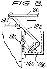
Fig.9 is a longitudinal sectional view of another filter component of the preferred embodiment illustrated in Fig.1
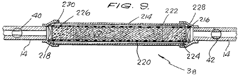
Fig.10 is a view of another component of the present invention
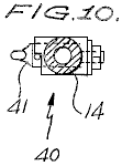
Fig.11 is an exploded, perspective view which illustrates the main components of the filter portion of the vapour equaliser of the present invention.
DETAILED DESCRIPTION OF THE PREFERRED EMBODIMENT
Referring now to the drawings, where parts are numbered the same in each drawing, and more particularly to Fig.1 which illustrates a preferred embodiment of the present invention as installed in a motor vehicle.
The preferred embodiment includes as its main components a fuel vapour tank 10 in which the fuel vapour is stored and generated for subsequent delivery to the internal combustion engine 20. On the top of fuel vapour tank 10 is mounted an air inlet control valve 12 whose structure and operation will be described in greater detail below.
The internal combustion engine 20 includes a standard intake manifold 18. Mounted upon the intake manifold 18 is a vapour equaliser chamber 16. Connected between the fuel vapour tank 10 and the vapour equaliser chamber 16 is a vapour conduit or hose 14 for conducting the vapours from within tank 10 to the chamber 16.
Reference numeral 22 indicates generally an air inlet control valve which is mounted on the vapour equaliser chamber 16. Thus, the system is provided with two separate air inlet control valves 12 and 22 which are respectively coupled via cables 24 and 26 to the throttle control for the motor vehicle which may take the form of a standard accelerator pedal 28. The air inlet control valves 12 and 22 are synchronised in such a fashion that the opening of the air inlet control valve 22 of the vapour equaliser 16 always precedes and exceeds the opening of the air inlet control valve 12 of the fuel vapour tank 10, for reasons which will become more clear later.
The cooling system of the vehicle conventionally includes a radiator 30 for storing liquid coolant which is circulated through the engine 20 in the well-known fashion. A pair of hoses 32 and 34 are preferably coupled into the normal heater lines from the engine 20 so as to direct heated liquid coolant from the engine 20 to a warming coil 36, preferably constructed of copper, which is positioned within vapour tank 10. I have found that the water circulation system consisting of hoses 32, 34 and 36 serves three distinct functions. Firstly, it prevents the vapour tank from reaching the cold temperatures to which it would otherwise be subjected as a result of high vacuum pressure and air flow through it. Secondly, the heated coolant serves to enhance vaporisation of the fuel stored within tank 10 by raising its temperature. Thirdly, the liquid coolant, after leaving tank 10 via conduit 34, has been cooled to the point where engine 20 may then be run at substantially lower operating temperatures to further increase efficiency and prolong the life of the engine.
Included in series with vapour conduit 14 is a filter unit 38 which is designed to retard the flow of fuel vapour from the tank 10 to the vapour equaliser 16. The precise structure of the filter unit 38 will be described in greater detail below. A thrust adjustment valve 40 is positioned upstream of the filter unit 38 in conduit 14 and acts as a fine adjustment for the idling speed of the vehicle. Positioned on the other side of filter unit 38 in conduit 14 is a safety shut-off valve 42 which comprises a one-way valve. Starting the engine 20 will open the valve 42 to permit the engine vacuum pressure to be transmitted to tank 10, but, for example, a backfire will close the valve to prevent a possible explosion. The tank 10 may also be provided with a drain 44 positioned at the bottom of the tank.
Positioned on the side of the vapour equaliser chamber 16 is a primer connection 46 which may be controlled by a dash mounted primer control knob 48 connected to tank 10 via conduit 47. A conduit 50 extends from the oil breather cap opening 52 in a valve cover 54 of the engine 20 to the vapour equaliser 16 to feed the oil blow-by to the engine as a means for eliminating valve clatter. This is believed necessary due to the extreme lean mixture of fuel vapour and air fed to the combustion cylinders of the engine 20 in accordance with the present invention.
Referring now to Fig.2 and Fig.3, the fuel vapour tank 10 of the present invention is illustrated in greater detail in orthogonal sectional views and is seen to include a pair of side walls 56 and 58 which are preferably comprised of heavy duty steel plate (e.g. 1/2" thick) in order to withstand the high vacuum pressures developed inside it. Tank 10 further comprises top wall 60 and bottom wall 62, and front and rear walls 64 and 66, respectively.
In the front wall 64 of tank 10 is positioned a coupling 68 for mating the heater hose 32 with the internal copper conduit 36. Tank 10 is also provided with a pair of vertically oriented planar support plates 70 and 72 which are positioned somewhat inside the side walls 56 and 58 and are substantially parallel to them. Support plates 70 and 72 lend structural integrity to the tank 10 and are also provided with a plurality of openings 74 (Fig.2) at the bottom of them to permit fluid communication through it. The bottom of tank 10 is generally filled with from one to five gallons of fuel, and the walls of tank 10 along with plates 70 and 72 define three tank chambers 76, 78 and 80 which are, by virtue of openings 74, in fluid communication with one another.
In the top wall 60 of tank 10 is formed an opening 82 for placing one end of vapour conduit 14 in fluid communication with the interior chamber 76 of tank 10. A second opening 84 is positioned in the top wall 60 of tank 10 over which the air inlet control valve 12 is positioned. The valve assembly 12 comprises a pair of conventional butterfly valves 86 and 88 which are coupled via a control rod 90 to a control arm 92. Control arm 92 is, in turn, pivoted under the control of a cable 24 and is movable between a solid line position indicated in Fig.2 by reference numeral 92 and a dotted line position indicated in Fig.2 by reference numeral 92’.
Rod 90 and valves 86 and 88 are journaled in a housing 94 having a base plate 96 which is mounted on a cover 98. As seen in Fig.1, the base plate 96 includes several small air intake ports or apertures 100 formed on both sides of the butterfly valves 86 and 88, which are utilised for a purpose to become more clear later on.
Rod 90 is also journaled in a flange 102 which is mounted to cover 98, while a return spring 104 for control arm 92 is journaled to cover 98 via flange 106.
Extending through the baffle and support plates 70 and 72 from the side chambers 78 and 80 of tank 10 to be in fluid communication with apertures 100 are a pair of air conduits 108 and 110 each having a reed valve 112 and 114 positioned at the ends, for controlling air and vapour flow through it. The reed valves 112 and 114 co-operage with the small apertures 100 formed in the base plate 96 to provide the proper amount of air into the tank 10 while the engine is idling and the butterfly valves 86 and 88 are closed.
Mounted to the front wall 64 of tank 10 is a pivot support member 132 for pivotally receiving a filter element which is indicated generally by reference numeral 134 and is illustrated in a perspective, partially cut away view in Fig.5. The unique, pivotable filter element 134 comprises a frame member 136 having a pin-receiving stub 138 extending along one side member of it. The actual filter material contained within the frame 136 comprises a layer of carbon particles 148 which is sandwiched between a pair of layers of sponge-like filter material which may, for example, be made of neoprene. The neoprene layers 144 and 146 and carbon particles 148 are maintained in place by top and bottom screens 140 and 142 which extend within, and are secured by, frame member 136. ,A thick-walled rubber hose 150 having a central annulus 151 is secured to the top of screen 140 so as to mate with opening 82 of top wall 60 (see Fig.2) when the filter assembly 134 is in its solid line operative position illustrated in Fig.2. In the latter position, it may be appreciated that the vapour conduit 14 draws vapour fumes directly from the filter element 134, rather than from the interior portion 76 of tank 10. In contradistinction, when the filter element 134 is in its alternate operative position, indicated by dotted lines in Fig.2, the vapour conduit 14 draws fumes mainly from the interior portions 76, 78 and 80 of tank 10.
Fig.4 is an enlarged view of one of the reed valve assemblies 114 which illustrates the manner in which the valve opens and closes in response to the particular vacuum pressure created within the tank 10. Valves 112 and 114 are designed to admit just enough air to the tank 10 from the apertures 100 at engine idle to prevent the engine from stalling.
Referring now to Fig.6, Fig.7 and Fig.8, the vapour equaliser chamber 16 of the present invention is seen to include front and rear walls 152 and 154, respectively, a top wall 156, a side wall 158, and another side wall 160. The vapour equaliser chamber 16 is secured to the manifold 18 as by a plurality of bolts 162 under which may be positioned a conventional gasket 164.
In the top wall 156 of the vapour equaliser 16 is formed an opening 166 for communicating the outlet end of vapour conduit 14 with a mixing and equalising chamber 168. Adjacent to the mixing and equalising chamber 168 in wall 154 is formed another opening 170 which communicates with the outside air via opening 178 formed in the upper portion of housing 176. The amount of air admitted through openings 178 and 170 is controlled by a conventional butterfly valve 172. Butterfly valve 172 is rotated by a control rod 180 which, in turn, is coupled to a control arm 182. Cable 26 is connected to the end of control arm 182 furthest from the centreline and acts against the return bias of spring 184, the latter of which is journaled to side plate 152 of vapour equaliser 16 via an upstanding flange 188. Reference numeral 186 indicates generally a butterfly valve operating linkage, as illustrated more clearly in Fig.8, and which is of conventional design as may be appreciated by a person skilled in the art.
Positioned below mixing and equalising chamber 168 is a filter unit which is indicated generally by reference numeral 188. The filter unit 188, which is illustrated in an exploded view in Fig.11, comprises a top plastic fluted cover 190 and a bottom plastic fluted cover 192. Positioned adjacent to the top and bottom covers 190 and 192 is a pair of screen mesh elements 194 and 196, respectively. Positioned between the screen mesh elements 194 and 196 is a support member 198 which is preferably formed of a sponge-like filter material, such as, for example, neoprene. The support member 199 has formed on its upper and lower surfaces, a pair of receptacles 200 and 202, whose diameters are sized similarly to the opening 166 in top plate 156 and the openings formed in the intake manifold 18 which are respectively indicated by reference numerals 210 and 212 in Fig.6.
Positioned in receptacles 200 and 202 are carbon particles 204 and 206, respectively, for vapour retardation and control purposes.
Referring now to Fig.9, the filter unit 38 mounted in vapour conduit 14 is illustrated in a longitudinal sectional view and is seen to comprise an outer flexible cylindrical hose 214 which is adapted to connect with hose 14 at both ends by a pair of adapter elements 216 and 218. Contained within the outer flexible hose 214 is a cylindrical container 220, preferably of plastic, which houses, in its centre, a mixture of carbon and neoprene filter fibres 222. At both ends of the mixture 222 are deposited carbon particles 224 and 226, while the entire filtering unit is held within the container 220 by end screens 228 and 230 which permit passage of vapours through it while holding the carbon particles 224 and 226 in place.
Fig.10 illustrates one form of the thrust adjustment valve 40 which is placed within line 14. This valve simply controls the amount of fluid which can pass through conduit 14 via a rotating valve member 41.
In operation, the thrust adjustment valve 40 is initially adjusted to achieve as smooth an idle as possible for the particular motor vehicle in which the system is installed. The emergency shut-off valve 42, which is closed when the engine is off, generally traps enough vapour between it and the vapour equaliser 16 to start the engine 20. Initially, the rear intake valves 12 on the tank 10 are fully closed, while the air intake valves 22 on the equaliser 16 are open to admit a charge of air to the vapour equaliser prior to the vapour from the tank, thus forcing the pre-existing vapour in the vapour equaliser into the manifold. The small apertures 100 formed in base plate 96 on tank 10 admit just enough air to actuate the reed valves to permit sufficient vapour and air to be drawn through vapour conduit 14 and equaliser 16 to the engine 20 to provide smooth idling. The front air valves 22 are always set ahead of the rear air valves 12 and the linkages 24 and 26 are coupled to throttle pedal 28 such that the degree of opening of front valves 22 always exceeds the degree of opening of the rear valves 12.
Upon initial starting of the engine 20, due to the closed condition of rear valves 12, a high vacuum pressure is created within tank 10 which causes the filter assembly 134 positioned in tank 10 to rise to its operative position indicated by solid outline in Fig.2. In this manner, a relatively small amount of vapour will be drawn directly from filter 134 through vapour conduit 14 to the engine to permit the latter to run on an extremely lean mixture.
Upon initial acceleration, the front air intake valve 22 will open further, while the rear butterfly assembly 12 will begin to open. The latter action will reduce the vacuum pressure within tank 10 whereby the filter assembly 134 will be lowered to its alternate operating position illustrated in dotted outline in Fig.2. In this position, the lower end of the filter assembly 134 may actually rest in the liquid fuel contained within the tank 10. Accordingly, upon acceleration, the filter assembly 134 is moved out of direct fluid communication with the opening 82 such that the vapour conduit 14 then draws fuel vapour and air from the entire tank 10 to provide a richer combustion mixture to the engine, which is necessary during acceleration.
When the motor vehicle attains a steady speed, and the operator eases off the accelerator pedal 28, the rear butterfly valve assembly 12 closes, but the front air intake 22 remains open to a certain degree. The closing of the rear air intake 12 increases the vacuum pressure within tank 10 to the point where the filter assembly 134 is drawn up to its initial operating position. As illustrated, in this position, the opening 82 is in substantial alignment with the aperture 151 of hose 150 to place the filter unit 134 in direct fluid communication with the vapour conduit 14, thereby lessening the amount of vapour and air mixture fed to the engine. Any vapour fed through conduit 14 while the filter 134 is at this position is believed to be drawn directly off the filter unit itself.
I have been
able to obtain extremely high mpg figures with the system of the present
invention installed on a V-8 engine of a conventional 1971 American-made
car. In fact, mileage rates in excess of
one hundred miles per
Obviously, numerous modifications and variations of the present invention are possible in light of the above teachings. For example, although described in connection with the operation of a motor vehicle, the present invention may be universally applied to any four-stroke engine for which its operation depends upon the internal combustion of fossil fuels. Therefore, it is to be understood that within the scope of the appended claims the invention may be practiced otherwise than as specifically described here.
The
Permanent Magnet Motor of Stephen Kundel
US Patent 7,151,332
19th December 2006
Inventor: Stephen Kundel
MOTOR HAVING RECIPROCATING AND ROTATING
PERMANENT MAGNETS
This patent describes a motor powered mainly by permanent magnets. This system uses a rocking frame to position the moving magnets so that they provide a continuous turning force on the output shaft.
ABSTRACT
A motor which has a rotor supported for rotation about an axis, and at least one pair of rotor magnets spaced angularity about the axis and supported on the rotor, at least one reciprocating magnet, and an actuator for moving the reciprocating magnet cyclically toward and away from the pair of rotor magnets, and consequently rotating the rotor magnets relative to the reciprocating magnet.
0561144 June, 1896 Trudeau
1724446 August, 1929
2790095 April, 1957 Peek et al.
3469130 September, 1969 Jines et al.
3703653 November, 1972
3811058 May, 1974 Kiniski
3879622 April, 1975 Ecklin
3890548 June, 1975 Gray
3899703 August, 1975 Kinnison
3967146 June, 1976 Howard
3992132 November, 1976 Putt
4011477 March, 1977 Scholin
4151431 April, 1979 Johnson
4179633 December, 1979 Kelly
4196365 April, 1980 Presley
4267647 May, 1981 Anderson et al.
4629921 December, 1986 Gavaletz
4751486 June, 1988 Minato
5402021 March, 1995 Johnson
5594289 January, 1997 Minato
5634390 June, 1997 Takeuchi et al.
5751083 May, 1998 Tamura et al.
5925958 July, 1999 Pirc
6169343 January, 2001 Rich, Sr.
6343419 February, 2002 Litman et al.
6841909 January, 2005 Six
20020167236 November, 2002 Long
20040140722 July, 2004 Long
BACKGROUND OF THE INVENTION
This invention relates to the field of motors. More particularly, it pertains to a motor whose rotor is driven by the mutual attraction and repulsion of permanent magnets located on the rotor and an oscillator.
Various kinds of motors are used to drive a load. For example, hydraulic and pneumatic motors use the flow of pressurised liquid and gas, respectively, to drive a rotor connected to a load. Such motors must be continually supplied with pressurised fluid from a pump driven by energy converted to rotating power by a prime mover, such as an internal combustion engine. The several energy conversion processes, flow losses and pumping losses decrease the operating efficiency of motor systems of this type.
Conventional electric motors employ the force applied to a current carrying conductor placed in a magnetic field. In a d. c. motor the magnetic field is provided either by permanent magnets or by field coils wrapped around clearly defined field poles on a stator. The conductors on which the force is developed are located on a rotor and supplied with electric current. The force induced in the coil is used to apply rotor torque, whose magnitude varies with the magnitude of the current and strength of the magnetic field. However, flux leakage, air gaps, temperature effects, and the counter-electromotive force reduce the efficiency of the motor.
Permanent dipole magnets have a magnetic north pole, a magnetic south pole, and magnetic fields surrounding each pole. Each magnetic pole attracts a pole of opposite magnetic polarity. Two magnetic poles of the same polarity repel each other. It is desired that a motor be developed such that its rotor is driven by the mutual attraction and repulsion of the poles of permanent magnets.
SUMMARY OF THE INVENTION
A motor according to the present invention includes a rotor supported for rotation about an axis, a first pair of rotor magnets including first and second rotor magnets spaced angularly about the axis and supported on the rotor, a reciprocating magnet, and an actuator for moving the reciprocating magnet cyclically toward and away from the first pair of rotor magnets, and cyclically rotating the first pair of rotor magnets relative to the reciprocating magnet. Preferably the motor includes a second pair of rotor magnets supported on the rotor, spaced axially from the first pair of rotor magnets, the second pair including a third rotor magnet and a fourth rotor magnet spaced angularly about the axis from the third rotor magnet. The reciprocating magnet is located axially between the first and second rotor magnet pairs, and the actuator cyclically moves the reciprocating magnet toward and away from the first and second pairs of rotor magnets.
The magnets are preferably permanent dipole magnets. The poles of the reciprocating magnet are arranged such that they face in opposite lateral directions.
The motor can be started by manually rotating the rotor about its axis. Rotation continues by using the actuator to move the reciprocating magnet toward the first rotor magnet pair and away from the second rotor magnet pair when rotor rotation brings the reference pole of the first rotor magnet closer to the opposite pole of the reciprocating magnet, and the opposite pole of the second rotor magnet closer to the reference pole of the reciprocating magnet. Then the actuator moves the reciprocating magnet toward the second rotor magnet pair and away from the first rotor magnet pair when rotor rotation brings the reference pole of the third rotor magnet closer to the opposite pole of the reciprocating magnet, and the opposite pole of the fourth rotor magnet closer to the reference pole of the reciprocating magnet.
A motor according to this invention requires no power source to energise a field coil because the magnetic fields of the rotor and oscillator are produced by permanent magnets. A nine-volt DC battery has been applied to an actuator switching mechanism to alternate the polarity of a solenoid at the rotor frequency. The solenoid is suspended over a permanent magnet of the actuator mechanism such that rotor rotation and the alternating polarity of a solenoid causes the actuator to oscillate the reciprocating magnet at a frequency and phase relation that is most efficient relative to the rotor rotation.
The motor is lightweight and portable, and requires only a commercially available portable d. c. battery to power an actuator for the oscillator. No motor drive electronics is required. Operation of the motor is practically silent.
Various objects and advantages of this invention will become apparent to those skilled in the art from the following detailed description of the preferred embodiment, when read in light of the accompanying drawings.
BRIEF DESCRIPTION OF THE DRAWINGS
These and other advantages of the present invention will become apparent to those skilled in the art from the following detailed description of a preferred embodiment when considered in the light of the accompanying drawings in which:
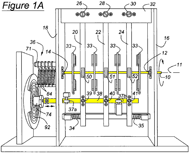
Fig.1A is a side view of a motor according to this invention;

Fig.1B is a perspective view of the motor of Fig.1A
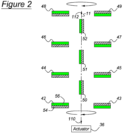
Fig.2 is a top view of the of motor of Fig.1A and Fig.1B showing the rotor magnets disposed horizontally and the reciprocating magnets located near one end of their range of travel
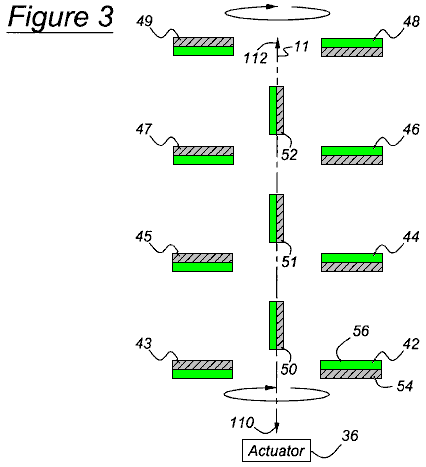
Fig.3 is a top view of the motor of Fig.2 showing the rotor magnets rotated one-half revolution from the position shown in Fig.2, and the reciprocating magnets located near the opposite end of their range of travel
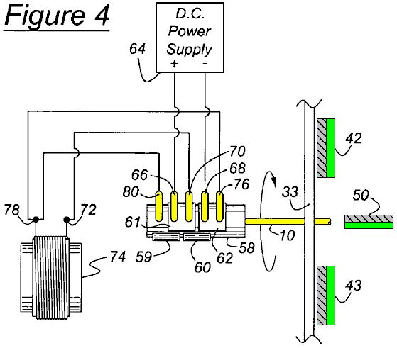
Fig.4 is a schematic diagram of a first state of the actuator
switching assembly of the motor of Fig.1
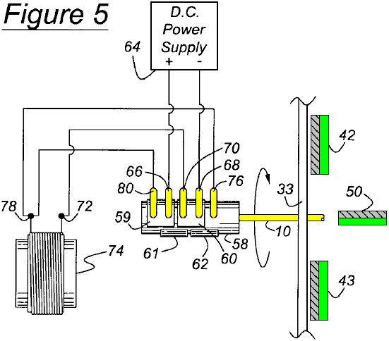
Fig.5 is a schematic diagram of a second state of the actuator
switching assembly of the motor of Fig.1
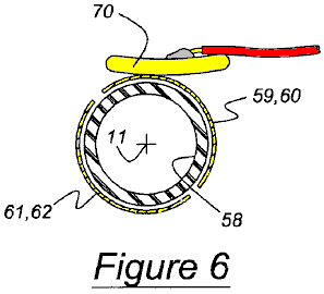
Fig.6 is cross sectional view of a sleeve shaft aligned with the rotor shaft showing a contact finger and bridge contact plates of the switching assembly
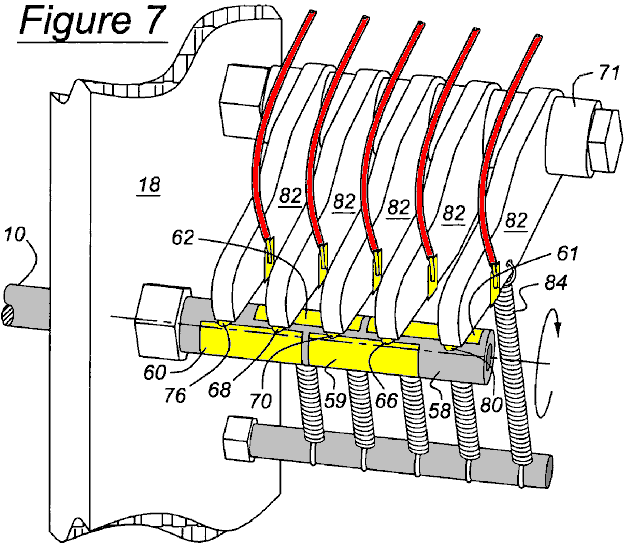
Fig.7 is an isometric view showing the switching contact fingers secured on pivoting arms and seated on the bridge connectors of the switching assembly
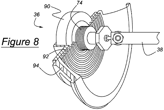
Fig.8 is isometric cross sectional view showing a driver that includes a solenoid and permanent magnet for oscillating the actuator arm in response to rotation of the rotor shaft
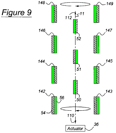
Fig.9 is a top view of an alternate arrangement of the rotor magnets, wherein they are disposed horizontally and rotated ninety degrees from the position shown in Fig.2, and the reciprocating magnets are located near an end of their range of displacement
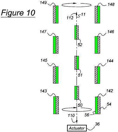
Fig.10 is a top view showing the rotor magnet arrangement of Fig.9 rotated one-half revolution from the position shown in Fig.9, and the reciprocating magnets located near the opposite end of their range of displacement; and
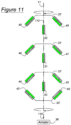
Fig.11 is a top view of the motor showing a third arrangement of the rotor magnets, which are canted with respect to the axis and the reciprocating magnets.
Fig.12 is a graph showing the angular displacement of the rotor shaft 10 and linear displacement of the reciprocating magnets
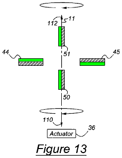
Fig.13 is a top view of a pair of rotor magnets disposed horizontally and reciprocating magnets located near one end of their range of travel
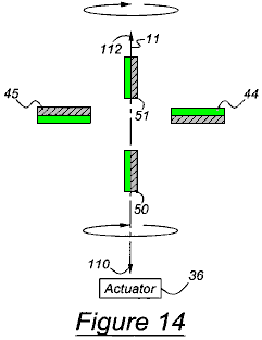
Fig.14 is a top view of the motor of Fig.13 showing the rotor magnets rotated one-half revolution from the position shown in Fig.13, and the reciprocating magnets located near the opposite end of their range of travel; and
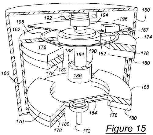
Fig.15 is a perspective cross sectional view of yet another embodiment of the motor according to this invention.
DETAILED
DESCRIPTION OF THE PREFERRED EMBODIMENT
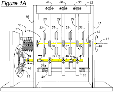
A motor according to this invention, illustrated in Fig.1A and Fig.1B includes a rotor shaft 10 supported for rotation about axis 11 on bearings 12 and 14 located on vertical supports 16 and 18 of a frame. An oscillator mechanism includes oscillator arms 20, 22 and 24 pivotally supported on bearings 26 , 28 and 30 respectively, secured to a horizontal support 32, which is secured at each axial end to the vertical supports 16 and 18. The oscillator arms 20, 22 and 24 are formed with through holes 15 aligned with the axis 11 of rotor shaft 10, the holes permitting rotation of the rotor shaft and pivoting oscillation of arms without producing interference between the rotor and the arms.
Extending in opposite diametric directions from the rotor axis 11 and secured to the rotor shaft 10 are four plates 33 , axially spaced mutually along the rotor axis, each plate supporting permanent magnets secured to the plate and rotating with the rotor shaft.
Each pivoting oscillator arm 20, 22 and 24 of the oscillator mechanism support permanent magnets located between the magnets of the rotor shaft. Helical coiled compression return springs 34 and 35 apply oppositely directed forces to oscillator arms 20 and 24 as they pivot about their respective pivotal supports 26 and 30, respectively. From the point of view of Fig.1A and Fig.1B, when spring 34 is compressed by displacement of the oscillator arm, the spring applies a force to the right to oscillator arm 20 which tends to return it to its neutral, starting position. When spring 35 is compressed by displacement of arm 24, the spring applies a force to the left to arm 24 tending to return it to its neutral, starting position.
The oscillator arms 20, 22 and 24 oscillate about their supported bearings 26, 28 and 30 , as they move in response to an actuator 36, which includes an actuator arm 38, secured through bearings at 39, 40 and 41 to the oscillator arms 20, 22 and 24, respectively. Actuator 36 causes actuator arm 38 to reciprocate linearly leftwards and rightwards from the position shown in Fig.1A and Fig.1B. The bearings 39, 40 and 41, allow the oscillator arms 20, 22 and 24 to pivot and the strut to translate without mutual interference. Pairs of guide wheels 37a and 37b spaced along actuator arm 38, each include a wheel located on an opposite side of actuator arm 38 from another wheel of the wheel-pair, for guiding linear movement of the strut and maintaining the oscillator arms 20, 22 and 24 substantially in a vertical plane as they oscillate. Alternatively, the oscillator arms 20, 22 and 24 may be replaced by a mechanism that allows the magnets on the oscillator arms to reciprocate linearly with actuator arm 38 instead of pivoting above the rotor shaft 10 at 26, 28 and 30.
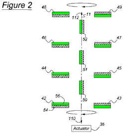
Fig.2 shows a first arrangement of the permanent rotor magnets 42 – 49 that rotate about axis 11 and are secured to the rotor shaft 10, and the permanent reciprocating magnets 50 – 52 which move along axis 11 and are secured to the oscillating arms 20, 22 and 24. Each magnet has a pole of reference polarity and a pole of opposite polarity from that of the reference polarity. For example, rotor magnets 42, 44, 46 and 48, located on one side of axis 11, each have a north, positive or reference pole 54 facing actuator 36 and a south, negative or opposite pole 56 facing away from the actuator. Similarly, rotation magnets 43, 45, 47 and 49, located diametrically opposite to rotor magnets 42, 44, 46 and 48, each have a south pole facing toward actuator 36 and a north pole facing away from the actuator. The north poles 54 of the reciprocating magnets 50 – 52 face to the right from the point of view seen in Fig.2 and Fig.3 and their south poles 56 face towards the left.

Fig.4 shows a switch assembly located in the region of the left-hand end of rotor shaft 10. A cylinder, 58, preferably formed of PVC, is secured to rotor shaft 10. Cylinder 58 has contact plates 59 and 60, preferably of brass, located on its outer surface, aligned angularly, and extending approximately 180 degrees about the axis 11, as shown in Fig.5. Cylinder 58 has contact plates 61 and 62, preferably made of brass, located on its outer surface, aligned angularly, extending approximately 180 degrees about the axis 11, and offset axially with respect to contact plates 59 and 60.
A D.C. power supply 64, has its positive and negative terminals connected electrically through contact fingers 66 and 68, to contact plates 61 and 62, respectively. A third contact finger 70, shown contacting plate 61, connects terminal 72 of a solenoid 74 electrically to the positive terminal of the power supply 64 through contact finger 66 and contact plate 61. A fourth contact finger 76, shown contacting plate 62, connects terminal 78 of solenoid 74 electrically to the negative terminal of the power supply 64 through contact finger 68 and contact plate 62. A fifth contact finger 80, axially aligned with contact plate 59 and offset axially from contact plate 61, is also connected to terminal 78 of solenoid 74.
Preferably the D.C. power supply 64 is a nine volt battery, or a D.C. power adaptor, whose input may be a conventional 120 volt, 60 Hz power source. The D.C. power supply and switching mechanism described with reference to Figs. 4 to 7, may be replaced by an A.C. power source connected directly across the terminals 72 and 78 of solenoid 74. As the input current cycles, the polarity of solenoid 74 alternates, the actuator arm 38 moves relative to a toroidal permanent magnet 90 (shown in Fig.8), and the reciprocating magnets 50 – 52 reciprocate on the oscillating arms 20, 22 and 24 which are driven by the actuator arm 38.

Fig.5 shows the state of the switch assembly when rotor shaft 10 has rotated approximately 180 degrees from the position shown in Fig.4. When the switch assembly is in the state shown in Fig.5, D.C. power supply 64 has its positive and negative terminals connected electrically by contact fingers 66 and 68 to contact plates 59 and 60, respectively. Contact finger 70, shown contacting plate 60, connects terminal 72 of solenoid 74 electrically to the negative terminal of the power supply 64 through contact finger 68 and contact plate 60. Contact finger 80, shown contacting plate 59, connects terminal 78 of solenoid 74 electrically to the positive terminal through contact finger 66 and contact plate 59. Contact finger 76, axially aligned with contact plate 62 and offset axially from contact plate 60, remains connected to terminal 78 of solenoid 74. In this way, the polarity of the solenoid 74 changes cyclically as the rotor 10 rotates through each one-half revolution.
Fig.6 shows in cross-section, the cylinder 58 which is aligned with and driven by the rotor shaft 10, a contact finger 70, and the contact plates 59 – 62 of the switching assembly, which rotate with the rotor shaft and cylinder about the axis 11 .
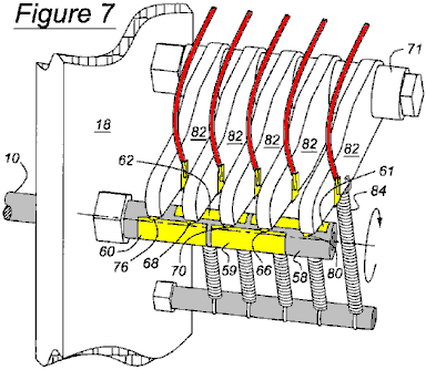
As Fig.7 illustrates, axially spaced arms 82 are supported on a stub shaft 71, preferably made of Teflon or another self-lubricating material, to facilitate the pivoting of the arms about the axis of the shaft 71. Each contact finger 66, 68, 70, 76 and 80 is located at the end of a arm 82, and tension springs 84, secured to each arm 82, urge the contact fingers 66, 68, 70, 76 and 80 continually toward engagement with the contact plates 59 – 62.
Fig.8 illustrates the actuator 36 for reciprocating the actuator arm 38 in response to rotation of the rotor shaft 10 and the alternating polarity of the solenoid 74. The actuator 36, includes the solenoid 74, the toroidal permanent magnet 90, an elastic flexible spider 92 for supporting the solenoid above the plane of the magnet, and a basket or frame 94, to which the spider is secured. The actuator arm 38 is secured to solenoid 74. The polarity of the solenoid 74 changes as rotor shaft 10 rotates, causing the solenoid and actuator arm 38 to reciprocate due to the alternating polarity of the solenoid relative to that of the toroidal permanent magnet 90. As the solenoid polarity changes, the actuator arm 38 reciprocates linearly due to the alternating forces of attraction and repulsion of the solenoid 74 relative to the poles of the magnet 90. The actuator arm 38 is secured to the oscillator arms 20, 22 and 24 causing them to pivot, and the reciprocating magnets 50 – 52, secured to the oscillator arms, to reciprocate. Alternatively, the reciprocating magnets 50 – 52 can be secured directly to the arm 38 , so that the magnets 50 – 52 reciprocate without need for an intermediary oscillating component.
It is important to note at this point in the description that, when two magnets approach each other with their poles of like polarity facing each other but slightly offset, there is a tendency for the magnets to rotate to the opposite pole of the other magnet. Therefore, in the preferred embodiment of the instant invention, the angular position at which the switch assembly of the actuator 36 changes between the states of Fig.4 and Fig.5 is slightly out of phase with the angular position of the rotor shaft 10 to help sling or propel the actuator arm 38 in the reverse direction at the preferred position of the rotor shaft. The optimum phase offset is approximately 5–8 degrees. This way, advantage is taken of each rotor magnet's tendency to rotate about its own magnetic field when slightly offset from the respective reciprocating magnet, and the repulsive force between like poles of the reciprocating magnets and the rotor magnets is optimised to propel the rotor magnet about the rotor axis 11, thereby increasing the motor's overall efficiency.
Fig.12 is a graph showing the angular displacement 96 of the rotor shaft 10 and linear displacement 98 of the reciprocating magnets 50 – 52. Point 100 represents the end of the range of displacement of the reciprocating magnets 50 – 52 shown in FIGS. 2 and 9, and point 102 represents the opposite end of the range of displacement of the reciprocating magnets 50 – 52 shown in FIGS. 3 and 10. Point 104 represents the angular position of the rotor magnets 42 – 49 when in the horizontal plane shown in FIGS. 2 and 9, and point 106 represents the angular position of the rotor magnets 42 – 49 when rotated one-half rotation to the horizontal plane shown in Fig.3 and Fig.10. Preferably, the reciprocating magnets 50 – 52 and rotor magnets 42 – 49 are out of phase: the reciprocating magnets lead and the rotor magnets lag by several degrees. The reciprocating magnets 50 – 52 reach the respective extremities of their range of travel before rotor rotation moves the rotor magnets 42 – 49 into the horizontal plane.
When the reference poles 54 and opposite poles 56 of the rotor magnets 42 – 49 and reciprocating magnets 50 – 52 are arranged as shown in Fig.2 and Fig.3, the rotor position is stable when the rotor magnets are in a horizontal plane. The rotor position is unstable in any other angular position, and it moves towards horizontal stability from any unstable position, and is least stable when the rotor magnets 42 – 49 are in a vertical plane. The degree of stability of the rotor shaft 10 is a consequence of the mutual attraction and repulsion of the poles of the rotor magnets 42 – 49 and reciprocating magnets 50 – 52 and the relative proximity among the poles. In Fig.2, the reciprocating magnets 50 – 52 are located at a first extremity of travel. In Fig.3, the reciprocating magnets 50 – 52 have reciprocated to the opposite extremity of travel, and the rotor magnets have rotated one-half revolution from the position shown in Fig.2.
When the rotor is stopped, its rotation can be easily started manually by applying torque in either direction. Actuator 36 sustains rotor rotation after it is connecting to its power source. Rotation of rotor shaft 10 about axis 11 is aided by cyclic movement of the reciprocating magnets 50 – 52, their axial location between the rotor magnet pairs 42 – 43 , 44 – 45 , 46 – 47 and 48 – 49, the disposition of their poles in relation to the poles of the rotor magnets, and the frequency and phase relationship of their reciprocation relative to rotation of the rotor magnets. Actuator 36 maintains the rotor 10 rotating and actuator arm 38 oscillating at the same frequency, the phase relationship being as described with reference to Fig.12.
With the rotor magnets 42 and 49 as shown in Fig.2, when viewed from above, the north poles 54 of the rotor magnets on the left-hand side of axis 11 face a first axial direction 110, i.e., toward the actuator 36, and the north poles 54 of the rotor magnets on the right-hand side of axis 11 face in the opposite axial direction 112, away from actuator 36. When the rotor magnets 42 – 49 are located as in Fig.2, the north poles 54 of reciprocating magnets 50 – 52 are adjacent the south poles 56 of rotor magnets 45, 47 and 49 , and the south poles 56 of reciprocating magnets 50 – 52 are adjacent the north poles 54 of rotor magnets 44, 46 and 48.
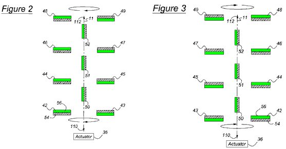
Furthermore, when the rotor shaft 10 rotates to the position shown in Fig.2, the reciprocating magnets 50 – 52 are located at, or near, one extremity of their axial travel, so that the north poles 54 of reciprocating magnets 50 – 52 are located close to the south poles 56 of rotor magnets 45, 47 and 49, respectively, and relatively more distant from the north poles 54 of rotor magnets 43, 45 and 47, respectively. Similarly, the south poles 56 of reciprocating magnets 50 – 52 are located close to the north poles of rotor magnet 44, 46 and 48, respectively, and relatively more distant from the south poles of rotor magnets 42, 44 and 46, respectively.
With the rotor magnets 42 and 49 rotated into a horizontal plane one-half revolution from the position of Fig.1B, when viewed from above as shown in Fig.3, the north poles 54 of reciprocating magnets 50 – 52 are located adjacent the south poles of rotor magnets 42, 44 and 46, and the south poles 56 of reciprocating magnets 50 – 52 are located adjacent the north poles 54 of rotor magnets 43, 45 and 47, respectively. When the rotor 10 shaft is located as shown in Fig.3, the reciprocating magnets 50 – 52 are located at or near the opposite extremity of their axial travel from that of Fig.2, such that the north poles 54 of reciprocating magnets 50 – 52 are located close to the south poles 56 of rotor magnet 42, 44 and 46, respectively, and relatively more distant from the north poles of rotor magnets 44, 46 and 48, respectively. Similarly, when the rotor shaft 10 is located as shown in FIG. 3, the south poles 56 of reciprocating magnets 50 – 52 are located close to the north poles of rotor magnet 43, 45 and 47, respectively, and relatively more distant from the south poles of rotor magnets 45, 47 and 49, respectively.
In operation, rotation of rotor shaft 10 in either angular direction is started manually or with a starter-actuator (not shown). Actuator 36 causes reciprocating magnets 50 – 52 to oscillate or reciprocate at the same frequency as the rotational frequency of the rotor shaft 10, i.e. one cycle of reciprocation per cycle of rotation, preferably with the phase relationship illustrated in Fig.12. When the reciprocating magnets 50 – 52 are located as shown in Fig.2, the rotor shaft 10 will have completed about one-half revolution from the position of Fig.3 to the position of Fig.2.
Rotation of the rotor 10 is aided by mutual attraction between the north poles 54 of the reciprocating magnets 50 – 52 and the south poles 56 of the rotor magnets 43, 45, 47 and 49 that are then closest respectively to those north poles of reciprocating magnets 50 – 52, and mutual attraction between the south poles of reciprocating magnets 50 – 52 and the north poles of the rotor magnets 42, 44, 46 and 48 that are then closest respectively to the north poles of the reciprocating magnets.
Assume rotor shaft 10 is rotating counterclockwise when viewed from the actuator 36, and the rotor magnets 42, 44, 46 and 48 are located above rotor magnets 43, 45, 47 and 49. With the rotor shaft 10 positioned so that the reciprocating magnets 50 – 52 are approximately mid-way between the positions shown in Fig.2 and Fig.3 and moving toward the position shown in Fig.2, as rotation proceeds, the south pole of each reciprocating magnet 50 – 52 applies a downward attraction to the north pole 54 of the closest of the rotor magnets 44, 46 and 48, and the north pole 54 of each reciprocating magnet 50 – 52 attracts upwards the south pole 56 of the closest rotor magnet 45, 47 and 49. This mutual attraction of the poles causes the rotor to continue rotating counterclockwise to the position of Fig.2.
Then the reciprocating magnets 50 – 52 begin to move toward the position shown in Fig.3, and rotor inertia overcomes the steadily decreasing force of attraction between the poles as they move mutually apart, permitting the rotor shaft 10 to continue its counterclockwise rotation into the vertical plane where rotor magnets 43, 45, 47 and 49 are located above rotor magnets 42, 44, 46 and 48. As rotor shaft 10 rotates past the vertical plane, the reciprocating magnets 50 – 52 continue to move toward the position of Fig.3, the south pole 56 of each reciprocating magnet 50 – 52 attracts downward the north pole of the closest rotor magnet 43, 45 and 47, and the north pole 54 of each reciprocating magnet 50 – 52 attracts upward the south pole 56 of the closest rotor magnet 42, 44 and 46, causing the rotor 10 to rotate counterclockwise to the position of Fig.3. Rotor inertia maintains the counterclockwise rotation, the reciprocating magnets 50 – 52 begin to move toward the position shown in Fig.2, and the rotor shaft 10 returns to the vertical plane where rotor magnets 43, 45, 47 and 49 are located above rotor magnets 42, 44, 46 and 48, thereby completing one full revolution.
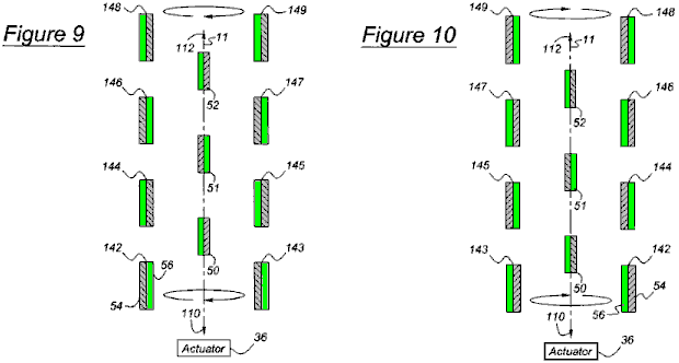
Fig.9 and Fig.10 show a second arrangement of the motor in which the poles of the rotor magnets 142 – 149 are parallel to, and face the same direction as those of the reciprocating magnets 50 – 52. Operation of the motor arranged as shown in Fig.9 and Fig.10 is identical to the operation described with reference to Fig.2 and Fig.3. In the embodiment of Fig.9 and Fig.10, the poles of the reciprocating magnets 50 – 52 face more directly the poles of the rotor magnets 142 – 149 in the arrangement of Fig.2 and Fig.3. The forces of attraction and repulsion between the poles are greater in the embodiment of Fig.9 and Fig.10, therefore, greater torque is developed. The magnitude of torque is a function of the magnitude of the magnetic forces, and the distance through which those force operate.

Fig.11 shows a third embodiment of the motor in which the radial outer portion of the rotor plates 33’ are skewed relative to the axis 11 such that the poles of the rotor magnets 42 – 49 are canted relative to the poles of the reciprocating magnets 50 – 52. Operation of the motor arranged as shown in Fig.11 is identical to the operation described with reference to Fig.2 and Fig.3.
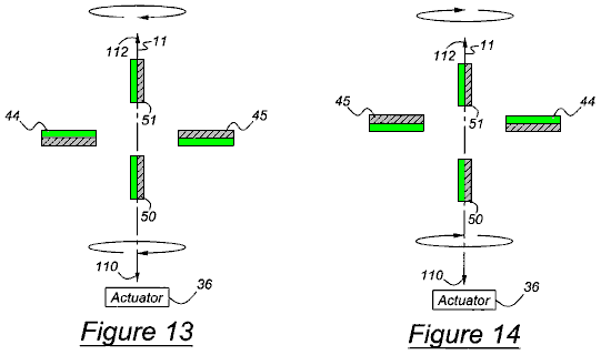
Fig.13 and Fig.14 show a fourth embodiment of the motor in which each of two reciprocating magnets 50 and 51 is located on an axially opposite side of a rotor magnet pair 44 and 45. Operation of the motor arranged as shown in Fig.13 and Fig.14 is identical to the operation described with reference to Fig.2 and Fig.3.
The direction of the rotational output can be in either angular direction depending on the direction of the starting torque.
The motor can produce reciprocating output on actuator arm 38 instead of the rotational output described above upon disconnecting actuator arm 38 from actuator 36, and connecting a crank, or a functionally similar device, in the drive path between the actuator and the rotor shaft 10. The crank converts rotation of the rotor shaft 10 to reciprocation of the actuator 30. In this case, the rotor shaft 10 is driven rotatably in either direction by the power source, and the output is taken on the reciprocating arm 38, which remains driveably connected to the oscillating arms 20, 22 and 24. The reciprocating magnets 50, 51 and 52 drive the oscillating arms 20, 22 and 24.
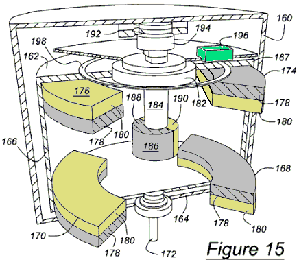
In the perspective cross sectional view shown in Fig.15, an outer casing 160 contains a motor according to this invention functioning essentially the same as the embodiment of the more efficient motor shown in Fig.1A and Fig.1B, but having a commercial appearance. The rotor includes discs 162 and 164 , which are connected by an outer drum 166 of nonmagnetic material. The upper surface 167 of drum 166 forms a magnetic shield surrounding the rotor. Mounted on the lower disc 164 are curved rotor magnets 168 and 170, which extend angularly about a rotor shaft 172, which is secured to the rotor. Mounted on the upper disc 162, are curved rotor magnets 174 and 176, which extend angularly about the rotor shaft 172. The reference poles are 178, and the opposite poles are 180. A bushing 182 rotates with the rotor.
A reciprocating piston 184, which moves vertically but does not rotate, supports reciprocating magnet 186, whose reference pole 188 and opposite pole 190 extend angularly about the axis of piston 184 .
A solenoid magnet 192, comparable to magnet 90 of the actuator 36 illustrated in Fig.8, is located adjacent a solenoid 194, comparable to solenoid 74 of Fig.4 and Fig.5. The polarity of solenoid 194 alternates as the rotor rotates. Simply stated, as a consequence of the alternating polarity of the solenoid 194, the reciprocating piston 184 reciprocates which, in turn, continues to advance the rotor more efficiently, using the attraction and repulsion forces between the reciprocating magnets 186 and rotor magnets 168, 170, 174 and 176 as described above and shown in any of the different embodiments using Fig.2, Fig.3, Fig.9, Fig.10, Fig.11, Fig.13 and Fig.14. Of course, just as the alternating polarity of the solenoid can put the motor in motion, so can the turning of the rotor, as described above. A photosensor 196 and sensor ring 198 can be used, as an alternative to the mechanical embodiment described in Fig.4 to Fig.7, to determine the angular position of the rotor so as to alternate the polarity of the solenoid 194 with the rotor to correspond with the phase and cycle shown in Fig.12.
In accordance with the provisions of the patent statutes, the present invention has been described in what is considered to represent its preferred embodiment. However, it should be noted that the invention can be constructed otherwise than as specifically illustrated and described without departing from its spirit or scope. It is intended that all such modifications and alterations be included insofar as they come within the scope of the appended claims or the equivalents thereof.
The
Magnetic Motor of Charles Flynn
US Patent 5,455,474 3rd October 1995 Inventor: Charles Flynn
MAGNETIC MOTOR CONSTRUCTION
This patent gives details of a permanent magnet motor which uses electromagnet shielding to achieve continuous rotation. The input power is very small with even a 9-volt battery being able to operate the motor. The output power is substantial and operation up to 20,000 rpm is possible. Construction is also very simple and well within the capabilities of the average handyman. It should be realised that the power of this motor comes from the permanent magnets and not from the small battery input used to prevent lock-up of the magnetic fields.
ABSTRACT
The present invention is a motor with permanent magnets positioned so that there is magnetic interaction between them. A coil placed in the space between the permanent magnets is used to control the magnetic interaction. This coil is connected to a source of electric potential and controlled switching so that closing the switch places a voltage across the coil and affects the magnetic interaction between the permanent magnets as to produce rotational movement of the output shaft.
3096467 Brushless d. c. motor with permanent magnet rotor July, 1963 Angus et al. 318/138
3569806 Starting Arrangement for Solid-State Motor March, 1971 Brailsford 318/254
3670189 Gated Permanent Magnet Motor June,
1972
3796039 Electric Micromotor March, 1974 Lucien 310/268
3883633 Commutatorless Motor May, 1975 Kohler 310/152
4151431 Permanent Magnet Motor April, 1979 Johnson 310/12
4187441 High-power-density Brushless DC Motor February, 1980 Oney 310/112
4758756 Vernier-type Electrodynamic Machine July, 1988 Pouillange 310/152
4875110 Rotary-head Apparatus with Motor Magnet October, 1989 Kazama 310/268
4972112 Brushless DC Motor November, 1990 Kim 310/181
5179307 Direct Current Brushless Motor January, 1993 Porter 310/268
Foreign References:
DE210005 July, 1960 310/181
JP0025153 February, 1982 310/181
JP01521078 September, 1982 310/152
JP0002840 January, 1987 310/152
BACKGROUND OF THE INVENTION
The present invention is an improvement over the inventions disclosed in patent applications 07/322,121 and 07/828,703. The devices disclosed in those applications relate to means to produce useful energy using permanent magnets as the driving source. This is also true of the present invention which represents an important improvement over the known constructions and one which is simpler to construct, can be made to be self starting, is easier to adjust, and is less likely to get out of adjustment. The present construction is also relatively easy to control, is relatively stable and produces an amazing amount of output energy considering the source of driving energy that is used. The present construction makes use of permanent magnets as the source of driving energy but shows a novel means of controlling the magnetic interaction between the magnet members in a manner which is relatively rugged, produces a substantial amount of output energy and torque, and in a device capable of being used to generate substantial amounts of energy that is useful for many different purposes.
The present invention resides has a fixed support structure with one or more fixed permanent magnets such as an annular permanent magnet mounted on it with the pole faces of the permanent magnet on opposite faces of the magnet. The device has one or more relatively flat coils positioned around the edge of one of the faces of the magnet, and a shaft extends through the permanent magnet with one or more other permanent magnets attached to it. The spaced permanent magnets and the fixed permanent magnet have their polarities arranged to produce a magnetic interaction between them. The device also includes a circuit for selectively and sequentially energising the coils to control the magnetic interaction between the magnets in such a manner as to produce rotation between them. Various methods can be used to control the application of energy to the coils including a timer or a control mechanism mounted on the rotating shaft. This design can be made to be self-starting or to be started with some initial help to establish rotation.
OBJECTS OF THE INVENTION
It is a principal object of the present invention to teach the construction and operation of a relatively simple, motor-like device using permanent magnets in an unique manner to generate rotational or other forms of movement.
Another object is to teach the construction and operation of a relatively simple, motor-like device having novel means for coupling and/or decoupling relatively moveable permanent magnets to produce motion.
Another object is to provide novel means for controlling the coupling and decoupling of relatively moveable permanent magnets.
Another object is to make the generation of rotational energy less expensive and more reliable.
Another object is to teach a novel way of generating energy by varying magnetic interaction forces between permanent magnets.
Another object is to provide an inexpensive way of producing energy.
Another object is to provide a substitute source of energy for use in places where conventional motors, generators and engines are used.
These and other objects and advantages of the present invention will become apparent after considering the following detailed specification of preferred embodiments in conjunction with the accompanying drawings.
BRIEF DESCRIPTION OF THE DRAWINGS
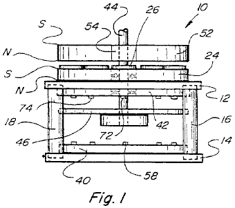
Fig.1 is a side view of a magnetically powered device constructed according to the present invention.
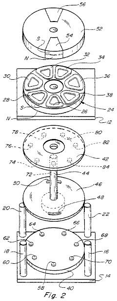
Fig.2 is an exploded view of the device shown in Fig.1.
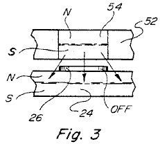
Fig.3 is a fragmentary side view of one of the movable magnets and the fixed magnet,
in one position of the device.
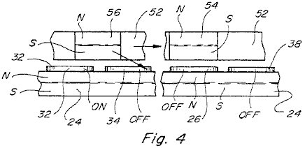
Fig.4 is a view similar to Fig.3 but showing the relationship between the other movable magnets
and the fixed magnet in the same rotational position of the device.
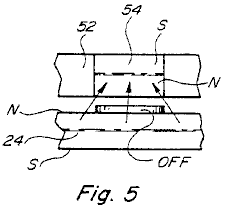
Fig.5 is a fragmentary view similar to Fig.3 but showing a repulsion interaction
between the relatively movable permanent magnets.
Fig.6 is a view similar to Fig.4 for the condition shown in Fig.5.
Fig.7 is a side view showing another embodiment which is capable
of producing even greater energy and torque.
Fig.8 is a fragmentary elevational view similar to Fig.3 for the device of Fig7.
Fig.9 is a view similar to Fig.4 for the construction shown in Fig.7.
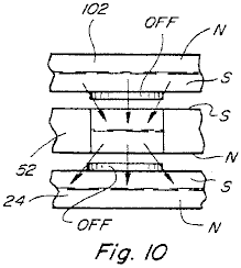
Fig.10 is a view similar to Fig.3 for the device shown in Fig.7 but
with the polarity of one of the fixed permanent magnets reversed.
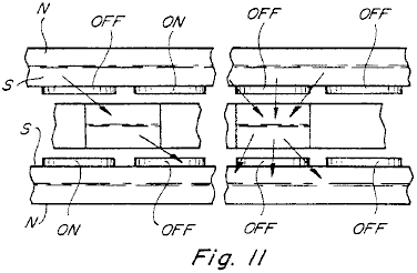
Fig.11 is a fragmentary view similar to Fig.4 for the device as shown in Fig.7 and Fig.10.
Fig.12 is a side elevational view of another embodiment of the device.

Fig.13 is a schematic circuit diagram of the circuit for the devices of Figs. 1, 7 and 12.
Fig.14 is a perspective view of another embodiment.
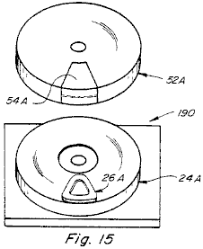
Fig.15 is a simplified embodiment of the device showing the use of one rotating magnet and one coil positioned in the plane between the rotating and stationary magnets.
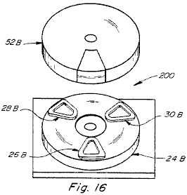
Fig.16 is a simplified embodiment of the device showing use of one movable magnet and three coils arranged to be in a plane between the rotating and stationary magnets.
Fig.17 is a side view of an air coil with a voltage applied across it and showing in dotted outline the field of the coil.
Fig.18 is a view similar to Fig.17 but showing the air coil positioned adjacent to one side of a permanent magnet showing in dotted outline the magnetic field of the permanent magnet with no electric potential applied across the air coil.
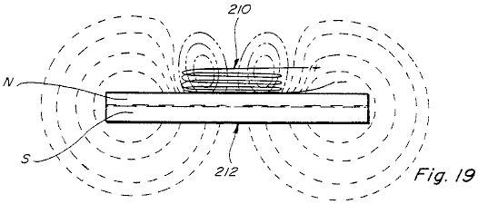
Fig.19 is a side view similar to Fig.18 with an electric potential applied across the air coil, showing in dotted
outline the shapes of the electric field of the air coil and the magnetic field of the permanent magnet.
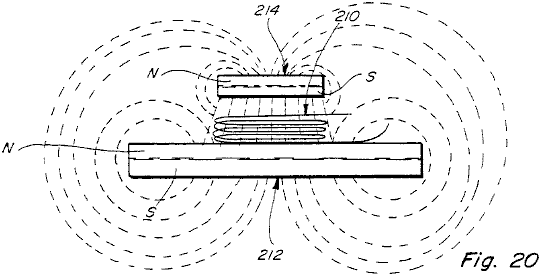
Fig.20 is a side view similar to Fig.19 but showing a second permanent magnet positioned above the first permanent magnet and showing in dotted outline the magnetic fields of the two permanent magnets when no electric potential is connected across the air coil.
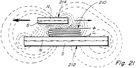
Fig.21 is a view similar to Fig.20 but with the permanent magnets in an different relative position and with a voltage applied across the air coil, said view showing the shapes of the electro-magnetic field of the air coil and the modified shapes of the magnetic fields of the two permanent magnets; and
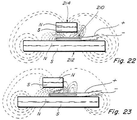
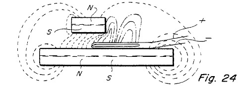
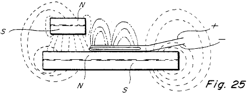
Fig.22 to Fig.25 are similar to Fig.21 and show the electro-magnetic field of the air coil and the magnetic fields of the magnets in four different relative positions of the permanent magnets.
DETAILED DESCRIPTION
In the drawings, the number 10 refers to a device constructed
according to the present invention. The
device 10 includes a stationary base
structure including an upper plate 12,
a lower plate 14, and spaced posts 16-22 connected between them.
Mounted on the upper plate 12 is a fixed permanent magnet 24 shown annular in shape which has its
North pole adjacent to the upper surface of plate 12 and its South pole facing away from plate 12.
Referring to Fig.2, the permanent magnet 24 is shown having seven coils 26-38 mounted flat on its upper
surface. Seven coils are shown, and the
coils 26-38 have electrical
connections made through plate 12 to
other circuit members which will be described later in connection with Fig.13.
Another member 40 is mounted on
the upper surface of the lower plate 14
and a similar member 42 is mounted
on the underside of the plate 12.
A shaft 44, (shown oriented vertically for convenience) extends through
aligned holes in the members 42, 12 and 24. The lower end of shaft 44 is connected to disk 46 which has a pair of curved openings 48 and 50 shown diametrically opposite to each other, a little in from the
edge of disc 46. The purpose of these openings 48 and 50 will be explained later on.
Shaft 44 is also connected to another disc 52 which is located on the shaft so as to be positioned adjacent to
the coils 26-38. Disc 52
has a pair of permanent magnets 54
and 56 mounted on or in it
positioned diametrically opposite to each other. Magnets 54
and 56 have their north and south
poles oriented as shown in Fig.2,
that is with north poles shown on their lower sides and their south poles on
the upper sides. This is done so that
there will be mutual magnetic attraction and coupling between the magnets 54 and 56 and the fixed magnet 24. The polarity of the magnets 54 and 56 and/or of the magnet 24
can also be reversed if desired for some purposes to produce relative magnetic
repulsion between them.
Referring again to Fig.2, the lower plate 40 is shown having a series of
phototransistors 58-70 mounted on
its upper surface and spaced out as shown.
These phototransistors are positioned under the centres of the coils 26-38 which are mounted on magnet 24.
An equal number of infra red emitters 72-84 are mounted on the under surface of the member 42 aligned with the
phototransistors. There are seven infra
red emitters 72-84 shown, each of
which is in alignment with a respective one of the seven phototransistors 58-70 and with one of the seven coils 26-38.
This arrangement is such that when the shaft 44 and the components attached to it, including discs 46 and 52, rotate relative to the other members including magnet 24, the curved openings 48 and 50 pass under the infra red emitters and cause the phototransistors
to switch on for a predetermined time interval.
This establishes a sequence of energised circuits which powers coils 26-38, one at a time, which in turn,
causes a momentary interruption of the magnetic interaction between one of the
permanent magnets 54 and 56 and magnet 24.
When a coil is mounted on top
of a permanent magnet such as permanent magnet 24 and energised it acts to concentrate the flux in a symmetrical
magnetic field resulting in a non-symmetrical field when another permanent
magnet is above the coil on magnet 24. This results in uneven or non-uniform forces
being produced when the coil is energised and this causes a torque between the
two permanent magnets, which tries to move one of the permanent magnets
relative to the other.
Fig.3 shows the
position when one of the magnets 54
is located immediately above one of the coils, say, coil 26. In this position there
would be magnetic coupling between the magnets 54 and 24 so long as
there is no voltage across the coil 26. However, if a voltage is placed across the
coil 26 it will interrupt the
magnetic coupling between the magnets 54
and 24 where the coil is
located. This means that if there is any
torque developed, it will be developed to either side of the coil 26.
Without energising the coil 26
there will be full attraction between the magnets 24 and 54 and no
rotational force will be produced.
Referring to Fig.4 there is shown the relative
positions of the movable magnets 54
and 56 for one position of disc 52.
For example, the magnet 54 is
shown located immediately above the coil 26
while the magnet 56 is shown
straddling portions of the coils 32
and 34. If, in this position, coil 32 is energised but coils 34 and 26 are not energised, then the magnetic coupling between magnet 56 and magnet 24 will be oriented at an angle shown illustrated by the arrow in Fig.4, and this attractive coupling
will tend to move disc 52 to the
right. Since coil 26 is not powered up, there is full coupling between magnet 54 and magnet 24 but this has no effect since it does not have a directional
force. At the same time, coil 38 which is the next coil over which
the magnet 54 will move, is also not
powered up and so it will have no rotational effect on disc 52.
As disc 52 continues to rotate, different coils in the group 26-38 will be energised in sequence to
continue to produce a rotational magnetic coupling force between disc 52 and magnet 24. It should be noted,
however, that all of the rotational force is produced by interaction between
the permanent magnets and none of the rotational force is produced by the coils
or by any other means. The coils are
merely energised in sequence to control where the magnetic interaction occurs,
and this is done in a manner to cause disc 52
to rotate. It should also be understood
that one, two, or more than two, permanent magnets such as the permanent
magnets 54 and 56 can be mounted on the rotating disc 52, and the shape and size of the rotating disc 52 can be adjusted accordingly to
accommodate the number of permanent magnets mounted in it. Also, disc 52 can be constructed of a non-magnetic material, the only
requirement being that sufficient structure be provided to support the
permanent magnets during rotation. This
means that disc 52 need not
necessarily be constructed to be round as shown in the drawing.
Fig.5 and Fig.6 are similar to Fig.3 and Fig.4 but show a construction where the permanent magnets 54 and 56 are turned over so that instead of having their north poles
facing magnet 24 they have their
south poles facing magnet 24 but on
the opposite side of the coils such as coils 26-38. The construction and
operation of the modified device illustrated by Fig.5 and Fig.6 is
similar to that described above except that instead of producing magnetic
attraction forces between the magnets 54
and 56 and the magnet 24, magnetic repulsion forces are
produced, and these repulsion forces can likewise be used in a similar manner
to produce rotation of the member 52,
whatever its construction.
Fig.7 shows a
modified embodiment which includes all of the elements shown in Fig.1 and Fig.2 but in addition has a second stationary permanent magnet 102 which is mounted above rotating
disc 52 and has its coil members
such as coil members 26A-38A mounted
on its underside. Magnet 102 operates with the magnets 54 and 56 similarly to the magnet 24
and can operate in precisely the same manner, that is by producing attraction
force between the magnet members or by producing repulsion forces between them,
each being used to produce relative rotational movement between the rotor and
the stator. It is also contemplated to
make the construction shown in Fig.7
so as to produce attraction forces between the magnets 54 and 56 on one side
thereof and cooperating repulsion forces which add to the rotation generating
forces produced on the opposite side.
Fig.8 and Fig.9 are similar to Fig.3 and Fig.4 but show the relationship between the magnets 54 and 56 and the members 24
and 102 located on opposite
sides. These figures show one form of
interaction between the rotating magnets 54
and 56 and the stationary magnets 24 and 102 located as shown in Fig.7. In this construction, the device produces
attractive rotating force only.
Fig.10 and Fig.11 are similar to Fig.8 and Fig.9 except that in these figures both attraction and repulsion
forces are shown being produced in association with the stationary magnets on
opposite sides of the rotating magnets.
Note also that the coils being energised on opposite sides of disc 52 are energised in a different
arrangement.
Fig.12 is a side
view similar to Fig.7 but showing
the way in which several stationary and rotating magnetic members such as the
discs 24 and 102 can be mounted on the same shaft, in almost any number of
repeating groups to increase the amount of torque produced by the device. In Fig.12,
the same power source and the same circuit arrangement can be used to energise
the phototransistors and the infra red emitters. However, depending upon
whether attraction or repulsion forces are used to produce the rotation or some
combination of them, will depend upon the order in which the coils associated
with the stationary magnetic members are energised.
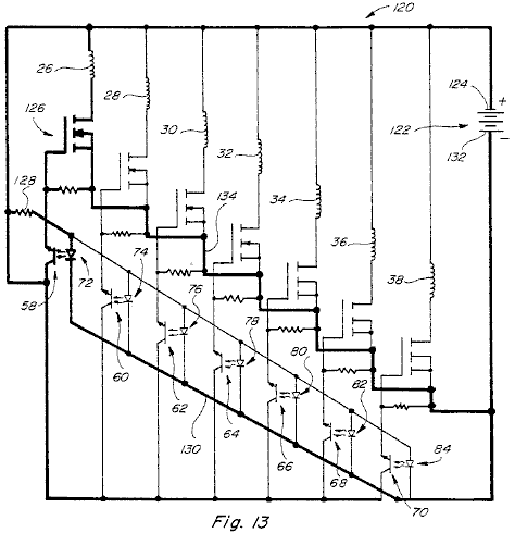
Fig.13 is a circuit
diagram for the device shown in Fig.1
and Fig.2, showing the circuit connections
for the coils 26-38 and for the
circuit elements associated with them. A
similar circuit can be used for the construction shown in Fig.7 and Fig.12. The circuit also includes connections to the
various phototransistors and infra red emitters.
In Fig.13, the circuit 120
is shown including a power supply 122
which may be a battery power supply, a rectified AC power supply or an AC or
pulsed power supply. The positive side 124 of the power supply 122 is shown connected to one side of
each of the coils 26-38, coil 26 and the circuits associated with it
being shown in bold outline and including connections to one side of a resistor
128 and to one side of the photo
transistors 58-70. The opposite side of the coil 26 is connected to one terminal of
MOSFET 126. The opposite side of the resistor 128 is connected to one side of the
infra red emitter 72, as well as to
the corresponding sides of all of the other infra red emitters 74-84.
The opposite sides of the infra red emitters 72-84 are connected by lead 130
to the negative terminal side 132 of
the power supply 122. With the circuit as shown, the infra red
emitters 72-84 are all continuously
energised and produce light which can be detected by the respective
phototransistors 58-70 when one of
the openings 48 or 50 passes between them. When this happens, the respective
phototransistor 58 will conduct and
in so doing will apply positive voltage on the associated MOSFET 126, turning the MOSFET on, and causing
the voltage of the source 122 to
also be applied across the coil 26. The circuit for this is from the source 122 through the coil 26, through the MOSFET 126 to and through the lead 134 to the opposite side of the source 122.
When the supply voltage is applied across the coil 26, it operates to limit or prevent magnetic communication between
whichever one of the magnets 54 or 56 happens to be positioned adjacent to
the coil 26 which is in the space
between that magnet 54 or 56 and the magnet 24. This circuit is shown in
bold in Fig.13. By properly timing and controlling the
application of voltage to the various coils 26-38 in the manner described, the magnetic coupling between the
magnets 54 and 56 and the magnet 24 can
be accurately controlled and cause angular magnetic attraction between the magnet
54 (or 56) and magnet 24, which
angular attraction (or repulsion) is in a direction to cause rotation of the
rotating parts of the structure shown in Figs.
1, 2, 7 and 12. It should be understood that each of the
coils 26-38 will be controlled in the
same manner, that is, will have a voltage appearing across it at the proper
time to control the direction of the magnetic coupling in a manner to produce
rotation. The rotating portions will
continue to rotate and the speed of rotation can be maintained at any desired
speed. Various means can be used to
control the speed of rotation such as by controlling the timing of the DC or
other voltage applied to the various coils, such as by using an alternating or
pulsed current source instead of a direct current source or by loading the
device to limit its rotational speed.
It is especially important to
note that the energy required to operate the subject device is minimal since
very little electrical energy is drawn when voltage is applied across the
various coils when they are energised.
A well known equation used
for conventional motor art, is:
Power (in watts) = Speed x Torque / 9.55
Hence,
W = S x T / 9.55
This equation has limited
application to the present device because in the present device the torque is
believed to be constant while the speed is the variable. The same equation can be rewritten:
T = 9.55 x W / S or
S = 9.55 X W / T
These equations, if
applicable, mean that as the speed increases, the watts divided by the torque
must also increase but by a factor of 9.55.
Thus if torque is constant or nearly constant, as speed increases, the
power output must increase and at a very rapid rate.
It should be understood that
the present device can be made to have any number of stationary and rotating
magnets arranged in stacked relationship to increase the power output, (see Fig.12) and it is also possible to use
any desired number of coils mounted on the various stationary magnets. In the constructions shown in Figs. 1, 7, and 12 seven coils
are shown mounted on each of the stationary magnets but more or fewer coils
could be used on each of stationary magnet depending upon the power and other
requirements of the device. If the number of coils is changed the number of
light sources and photo-detectors or transistors will change accordingly. It is also important to note that the timing
of the turning on of the various phototransistors is important. The timing should be such as that illustrated
in Fig.4, for example, when one of
the coils such as coil 32 is
energised to prevent coupling in one direction between magnet 56 and magnet 24, the adjacent coil 34
will not be energised. The reasons for
this have already been explained.
Fig.14, shows
another embodiment 140 of this
motor. This includes a stationary
permanent magnet 142 which has a
flat upper surface 144 and a lower
surface 146 that is
circumferentially helical so that the member 142 varies in thickness from a location of maximum thickness at 148 to a location of minimum thickness at
150.
The thickness of the member 142
is shown varying uniformly. Near the
location of the thickest portion 148
of the permanent magnet 142 and
adjacent to the surface 144 is an
air coil 152 shown formed by a
plurality of windings. A shaft member 154 is journaled by the bearing 156 to allow rotation relative to the
stationary permanent magnet 142 and
is connected to a rotating disc 158. The disc includes four spaced permanent
magnets 160, 162, 164 and 166 mounted on or in it. The permanent magnets 160-166 are positioned to rotate close to the stationary permanent
magnet 142 but with the coil 152 positioned between them. Coil 152
is connected into a circuit similar to that shown in Fig.13 and so the circuit will not be described again.
The principals of operation
of the device 140 shown in Fig.14 are similar to those described
above in connection with Fig.1 and
other figures. It is important to note,
however, that the permanent magnets 160-166
rotate relative to the permanent magnet 142
because of the increasing coupling between them and the permanent magnet due to
the increasing peripheral thickness of the permanent magnet. Thus the member 158 will rotate in a counter-clockwise direction as shown, and each
time one of the magnets 160-166
moves into a position adjacent to the thickest portion 148 of the fixed permanent magnet 142 the coil 152 will
have voltage applied across it, otherwise there would be a tendency for the
member 158 to stop or reduce the
rotational force. In order to overcome
this the coil 152 is energised each
time one of the permanent magnets 160-166
is in the position shown. The rotating
disc 158 is connected through the
shaft 154 to rotating disc 168 which has four openings 170, 172, 174 and 176 corresponding to the locations of the
permanent magnets 160-166 so that
each time one of the permanent magnets moves to a position adjacent to the
thickest portion 148 of the
stationary permanent magnet 142 the
coil 152 will be energised and this
will reduce or eliminate the coupling between the rotating and stationary
magnets that would otherwise slow the rotating portions down.
The circuit connected to the
coil 152 includes the same basic
elements described above in connection with Fig.13 including varying a photocell 178, an infra red emitter 180
and a MOSFET 182 connected into a
circuit such as that shown in Fig.13. The timing of the energising of the coil 152 is important and should be such
that the coil will be energised as the respective permanent magnets 160-166 move to a position in alignment
or substantial alignment with the thickened portion 148 of the stationary permanent magnet 142.
Fig.15 shows a basic
simplified form 190 of the present
device which includes a rotary member 52A
having a single permanent magnet portion 54A
mounted on it. The device also has a
stationary permanent magnet 24A with
a single air coil 26A positioned in
the space between the members 52A
and 24A in the manner already
described. The construction 190 is not self-starting as are the
preferred embodiments such as embodiment 10
but the rotary portions will rotate continuously once the device is started as
by manually rotating the rotary portions.
The construction 190 will
have other portions as described above but the output from the construction
will be less than the output produced by the other constructions.
Fig.16 shows another
simplified version 200 of the device
wherein the member 52B is similar to
the corresponding rotating member 52A
shown in Fig.15. However, the fixed structure including the
permanent magnet 24B has three
windings 26B, 28B and 30B located at
spaced intervals adjacent to the upper surface of it. The construction shown in Fig.16 will produce more output than
the construction shown in Fig.15 but
less than that of the other constructions such as that shown in Figs. 1, 2, 7 and 12. Obviously, many other
variations of the constructions shown in the application are also possible
including constructions having more or fewer coils, more or fewer rotating
magnetic portions, more or fewer rotating members such as disc 52 and more or fewer stationary members
such as magnets 24 and 142.
Figs.17-25
illustrate some of the underline principles of the present invention.
Fig.17 shows an air
coil 210, positioned in space, with
an electric potential applied across it.
With the energising voltage applied, the electro-magnetic field of air
coil 210 extends substantially
equally in the space above and below the coil as shown in dotted outlined.
Fig.18 shows the air
coil 210 positioned adjacent to one
side (the north side) of permanent magnet 212. In Fig.18
no voltage is applied across the air coil 210
and therefore the coil does not produce an electro-magnetic field as in Fig.17.
Under these circumstances, the air coil 210 has no effect on the magnetic field of the permanent magnet 212 and the field of the permanent
magnet is substantially as shown by the dotted outlines in Fig.18.
Fig.19 is similar to
Fig.18 except that in Fig.19 the air coil 210 has an electric potential applied
across it and therefore has an established electro-magnetic field shown again
by dotted outline.
The electro-magnetic field of
the air coil 210 modifies the
magnetic field of the permanent magnet 212
in the manner shown. If coil 210 is placed in contact with, or close
to the surface of, the permanent magnet and it is energised so that its
polarity is opposite to that of the permanent magnet then the field produced is
similar to that shown in Fig.19. Note that the field of coil 210 and the field of the permanent
magnet 212 directly beneath the air
coil 210 are in opposition and
therefore act to cancel one another.
Coil 210 would be defined to
produce a counter-magnetomotive force which acts to cancel the field of the
permanent magnet 212 in the region
where the air coil 210 exists and
the amount of the field in that region of the permanent magnet 212 that is cancelled is the remainder
of the difference in magnetomotive force between the region of the permanent
magnet 212 and the counter magnetomotive
force of the air coil 210. Note that, since the field of permanent
magnet 212 is only altered in the
region of the air coil 210, the
geometric magnetic field characteristics of the permanent magnet 212 can be altered selectively based
upon the size of the coil 210, the
number of air coils 210 and the
amount of counter magnetomotive force being produced by the air coil 210.
Fig.20 is similar to
Fig.19 except that a second
permanent magnet 214 is positioned
at a location spaced above the air coil 210. In Fig.20
no voltage is applied across the air coil 210
and therefore the air coil 210 does
not have an electro-magnetic field. Thus
Fig.20 shows only the combined
affect of the fields of the permanent magnets 212 and 214. Since the permanent magnets 212 and 214 are positioned so that their respective north and south poles
are close together, there will be a strong attractive force between them at the
location of the air coil 210.
Fig.21 is a view
similar Fig.20 but with an electric
potential applied across the air coil 210
and with the upper permanent magnet 214
displaced to the left relative to its position in Fig.20. Note that in Fig.21 the shape of the
electro-magnetic field of the air coil 210
is concentrated and shifted somewhat to the right and upward. This shift of the
electro-magnetic field concentrates the magnetic coupling between the magnets 212 and 214 to the left thereby increasing the tendency of the upper
permanent magnet 214 to move to the
left. A much smaller magnetic coupling
occurs between the right end of the permanent magnets 212 and 214 and thus the
force tending to move the permanent magnet 214
to the right is much less than the force tending to move it to the left. This is illustrated by the size of the arrows
shown in Fig.21.
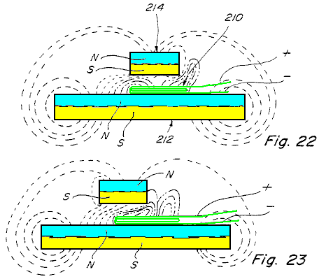
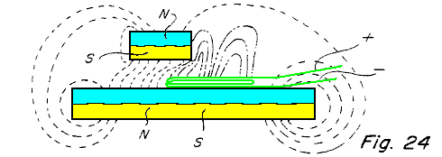
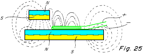
Figs. 22-25 show
four different positions of the upper permanent magnet 214 relative to the lower permanent magnet 212. In Fig.22 because of the position of the upper permanent magnet 214 relative to the air coil 210 there is a concentration of the
magnetic coupling force tending to move the upper permanent magnet 214 to the left. This force increases in Fig.23 and Fig.24 until
the upper permanent magnet 214
reaches the position shown in Fig.25
where all of the magnetic coupling is directed substantially vertically between
the permanent magnets 212 and 214 and in this position there is
little or no torque as a result of coupling energy between the permanent
magnets 212 and 214 tending to move them relative to one another.
The principles illustrated in
Figs. 17-25 are at the heart of the
present invention and explain where the energy comes from to produce relative
movement between the permanent magnets.
The present device has application for very
many different purposes and applications including almost any purpose where a
motor or engine drive is required and where the amount of energy available
and/or required to produce the driving force may vary little to nil. Applicant has produced devices of the type
described herein capable of rotating at very high speed in the order of
magnitude of 20,000 RPMs and with substantial torque. Other lesser speeds can
also be produced, and the subject device can be made to be self starting as is
true of the constructions shown in Figs.
1, 2, 7 and 12. Because of the low power required to operate
the device applicant has been able to operate same using a commercially
available battery such as a nine volt battery.
The Power
Plant of Claude Mead and William Holmes
US Patent 4,229,661 21st October
1980 Inventors: Claude Mead and
William Holmes
POWER PLANT FOR CAMPING TRAILER
Note: This patent is not a free-energy patent, but it does provide a suggestion for an integrated and practical system for providing power for people living in a caravan which is frequently off-grid but which occasionally is positioned where electrical mains power is available. It describes a practical system for storing wind energy for high-power electrical power supply, and so is of interest.
ABSTRACT
A power plant for mobile homes, camping trailers, and the like, capable of capturing low-powered wind energy, storing the energy in the form of compressed air, and delivering it on demand in the form of household electrical current. The device comprises a wind turbine which drives an air compressor which feeds a storage tank. When required, the compressed air drives a turbine coupled to an electrical generator. Various pressure regulators are used to control the speed of the generator. The wind turbine is also coupled to an alternator which keeps a bank of batteries charged. A DC motor running on the batteries, is used when necessary, to boost the drive of the air compressor during periods of heavy or long power drain. Provision is made for rapidly recharging the power plant from either a supply of compressed air or from an AC power source.
2230526 Wind power plant February, 1941 Claytor 290/44
2539862 Air-driven turbine power plant January, 1951 Rushing 290/44
3315085 Auxiliary power supply for aircraft April, 1967 Mileti et al. 290/55
3546474 Electrohydraulic Transmission of Power December, 1979 DeCourcy et al. 290/1
4150300 Electrical and thermal system for buildings April, 1979 VanWinkle 290/55
BACKGROUND OF THE INVENTION
The current shortage of fossil fuel and public concern for the quality of the environment have triggered a hurried search for alternate forms of energy. The capture and use of solar energy, and its derivative, wind power, is the object of many new inventions. Due to the inefficiency of the collector device and storage media, use of these forms of energy has been limited to low-power stationery applications. Yet wind power should be adequate for any application requiring very low power or a short, occasional low to medium power supply of energy. These circumstances are encountered, for instance, in a refrigerated railroad car where occasional bursts of power are required to run the refrigerating system in order to maintain a low temperature inside the car. Similar circumstances are found in some mobile housing units such as a camping trailer. There, again, a supply of household current might be necessary for a short time between long periods of travel. In such instances, a system can be devised for accumulating energy generated by a wind turbine powered by the wind or by the air draft created by the motion of the vehicle. It is further desirable that the power system be capable of being replenished from non-polluting energy sources which can be encountered along the travel route.
SUMMARY OF THE INVENTION
It is accordingly an object of the instant invention to provide a novel power plant for mobile homes, and the like, which captures wind energy, stores it in the form of compressed air, and delivers it on demand in the form of household electrical current.
Another object of this invention is to provide a power plant which does not discharge polluting effluents into the atmosphere.
Still another object of the invention is to provide a power plant which can be recharged by capturing the effect of the wind, or the effect of the air stream created by the movement of the vehicle.
A further object of the invention is to provide a power plant which can be recharged from a household current electrical outlet.
It is also an object of this invention to provide a power plant which can be replenished from a source of compressed air such as those found in automotive service stations.
An additional object of the invention is to provide a power plant which is responsive to a very low level of wind energy for a short period of time.
These and other objects are achieved by a power plant which comprises a wind turbine driving an air compressor. The air supply of the compressor is stored in the tank and used on demand to activate a turbine. The turbine, in turn, is coupled to a generator which creates household current. The wind turbine is also coupled to generators which charge a series of electrical batteries. On occasions when the AC power drain requires it, a motor running on the batteries is used to boost the output of the air compressor. Provision is made for driving the compressor from an outside AC power source. The air tank has a separate inlet through which it can be replenished from a source of compressed air.
THE DRAWINGS

Fig.1 is the general block diagram of the entire power plant;

Fig.2 is a front elevation of the wind turbine and of its mechanical coupling to the drive shaft;

Fig.3 is a cross-sectional view taken along line 3--3 of Fig.2 showing the propeller linkage mechanism in the engaged position;
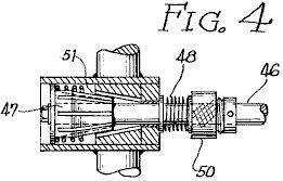
Fig.4 is a view similar to the one illustrated in Fig.3 but showing the propeller linkage mechanism in the disengaged position.
DESCRIPTION OF THE PREFERRED EMBODIMENT OF THE INVENTION
Referring now to Fig.1, there is shown a diagramatic representation of the preferred embodiment of the invention. A wind turbine comprising a propeller 1 and an orthogonal coupling assembly 2 drives a shaft 3 connected to a centrifugal clutch 4. This type of clutch is designed to engage itself when the speed of the drive shaft 3 reaches a certain minimum preset limit. The plate of the clutch is first connected to a compressor 5 and second to two DC generators 6 and 7. Block 5 represents a adiabatic compressor requiring an input drive of approximately one-fourth horsepower.
The output of the compressors 5 is protected by a check valve and leads into a pipe 8 connected to a tank inlet pipe 9. The inlet pipe 9 feeds into a holding tank 10 capable of holding sixty gallons of compressed air under a maximum pressure of 200 pounds per square inch. The DC generators 6 and 7 supply a series of electrical batteries 23. The batteries feed a DC motor 16. The DC motor is in turn connected to a second compressor 17. The second compressor 17 is similar to the first compressor 5 and is connected through to pipe 18 to the tank inlet pipe 9. A third compressor 19 similar to the first and second compressors is also connected to the tank inlet pipe 9 through pipe 20. The third compressor 19 is powered by an AC motor 21.
A pressure limit switch assembly 14 senses the pressure in the holding tank through a pipe 13. A high pressure switch within the assembly 14 is activated when the holding tank reaches the maximum safely allowable pressure. This switch through line 15 causes the disengagement of the clutch 4 and turns off DC motor 16 and AC motor 21. A second switch within the assembly 14 is activated when the holding pressure falls below a preset limit.
This second switch through line 15 turns on the DC motor 16. It can now be seen that when the tank pressure is below the lowest limit, both the first and second compressors 15, 17 will be activated. When the tank pressure goes above the lowest preset limit, only the first compressor 5 will be activated. If the holding tank pressure reaches the maximum tolerable limit all the compressors will be deactivated. The engagement speed of the centrifugal clutch 4 is set to a level corresponding to the minimum power necessary to drive the first compressor 5 and the DC generators 6 and 7. If the speed of the wind falls below that level, the shaft 3 will be free-running.
The holding tank 10 has a separate inlet 11 protected by a check valve 12. The holding tank is connected to a turbine feed tank 30 through pipe 24 controlled by valve 25. The turbine feed tank 30 is connected to the inlet of a turbine 33 through pipe 31 controlled by valve 32. The turbine 33 is powered by the expansion of the compressed air supplied by the turbine feed tank 30. The turbine 33 is similar to the compressed air motors used in certain impactors and drills. The turbine drives an AC generator 35 designed to supply approximately five kilowatts of household current at 60 Hz and 110 volts. The turbine is turned on by means of the valve 32 controlled by an/off switch 36. The speed of the turbine 33 is determined by the pressure of the air accumulated in the turbine tank 30. The pressure is monitored by sensor 27 connected to the turbine feed tank 30 by pipe 26. Sensor 27 contains a set of high and low limits. When the turbine feed tank pressure falls below the low limit, valve 25 is opened through control line 28. When the pressure in the turbine feed tank 30 reaches the high limit, the valve 25 is closed. The high and low limit of sensors 27 are not fixed but subject to minor variations in response to the speed of the turbine 33.
The speed of the turbine 33 and of the generator 35 is monitored by speed sensor 34. The output of the speed sensor 34 is inversely proportional to the speed of the turbine 33. The speed sensor signal 29 is fed to sensor 27. If the output frequency of the generator 35 deviates from the required 60 Hz, the high and low limits of the sensor 27 are either increased or decreased. If the speed of the generator is slowed down by an increase in the load current, the high and low limits of sensor 27 are raised in order to raise the pressure in turbine feed tank 30. The turbine 33 will respond to the pressure change by increasing its rotational speed. The output of the generator 35 is made available for use through lines 38 and 40 controlled by a switch 37.
The pressure in the holding tank 10 may be boosted from two external sources. First, compressed air may be introduced through inlet 11. Second, the AC motor 21 may be connected to an external source of electrical energy through lines 39 and 40 controlled by switch 37. The external electrical source may also be applied to a battery charger 22 which supplies the series of batteries 23. In an alternate version of the preferred embodiment, it is suggested that an AC/DC converter 41 be used to drive the DC motor 16 from the external electrical supply. In such a case, the AC motor 23 and the third compressor 19 are not necessary.
The power plant just described is primarily designed to be installed on board a camping trailer. This power plant will accumulate wind (“aeolian”) energy during the periods when the wind is blowing or the trailer is in motion. The energy is stored in two forms. First, it is stored in the form of compressed air in the holding tank 10. Second, it is stored in the form of DC current in the series of batteries 23. Both storage media are ecologically clean. Furthermore, the electrical system can boost the power of the compressed air system during periods of heavy power drain or long use. For added convenience, the system can be refuelled from an external source of electrical energy such as a household outlet or from an external source of compressed air such as those found in service stations for use by vehicle drivers. It should be noted also that this power plant is versatile in that it can be driven not only from the movement of fluids such as air or water, but also from the movement of the vehicle. In the later case, the shaft 3 would be coupled directly to the wheel of the vehicle.
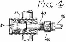
Referring now
to Figs. 2 through 4, there is shown the details of the
propeller 1 and coupling
The various mechanical and electro-mechanical components of the power plant such as the centrifugal clutch, compressors, generators, turbines, valves and pressure-activated switches are well known to those skilled in the art.
The speed sensor 34 may be implemented with an electronic integrator whose output signal 29 amplitude is proportional to the frequency of AC generator 35. The signal 29 is then used to modulate the sensitivity of sensor switches 27. This technique is also well known to those skilled in the electro-mechanical arts.
Modifications, other than those suggested, can be made to the embodiment of the invention just described without departing from the spirit of the invention and the scope of the appended claims.
The
Motionless Generator of Graham Gunderson
Graham Gunderson’s Solid-State Electric Generator is shown in US Patent Application 2006/0163971 A1 of 27th July 2006. The details are as follows:
Abstract
A solid-state electrical generator including at least one permanent magnet, magnetically coupled to a ferromagnetic core provided with at least one hole penetrating its volume; the hole(s) and magnet(s) being placed so that the hole(s) intercept flux from the permanent magnet(s) coupled into the ferromagnetic core. A first wire coil is wound around the ferromagnetic core for the purpose of moving the coupled permanent magnet flux within the ferromagnetic core. A second wire is routed through the hole(s) penetrating the volume of the ferromagnetic core, for the purpose of intercepting this moving magnetic flux, thereby inducing an output electromotive force. A changing voltage applied to the first wire coil causes coupled permanent magnet flux to move within the core relative to the hole(s) penetrating the core volume, thus inducing electromotive force along wire(s) passing through the hole(s) in the ferromagnetic core. The mechanical action of an electrical generator is therefore synthesised without the use of moving parts.
Background
This invention relates to a method and device for generating electrical power using solid state means.
It has long been known that moving a magnetic field across a wire will generate an electromotive force (EMF), or voltage, along the wire. When this wire is connected in a closed electrical circuit, an electric current, capable of performing work, is driven through this closed circuit by the induced electromotive force.
It has also long been known that this resulting electric current causes the closed circuit to become encircled with a secondary, induced magnetic field, whose polarity opposes the primary magnetic field which first induced the EMF. This magnetic opposition creates mutual repulsion as a moving magnet approaches such a closed circuit, and a mutual attraction as that moving magnet moves away from the closed circuit. Both these actions tend to slow or cause “drag” on the progress of the moving magnet, causing the electric generator to act as a magnetic brake, whose effect is in direct proportion to the amount of electric current produced.
Historically, gas engines, hydroelectric dams and steam-fed turbines have been used to overcome this magnetic braking action which occurs within mechanical generators. A large amount of mechanical power is required to produce a large amount of electrical power, since the magnetic braking is generally proportional to the amount of electrical power being generated.
There has long been felt the need for a generator which reduces or eliminates the well-known magnetic braking interaction, while nevertheless generating useful electric power. The need for convenient, economical and powerful sources of renewable energy remains urgent. When the magnetic fields within a generator are caused to move and interact by means other than applied mechanical force, electric power can be supplied without the necessity of consuming limited natural resources, thus with far greater economy.
Summary of the Invention
It has long been known that the source of the magnetism within a permanent magnet is a spinning electric current within ferromagnetic atoms of certain elements, persisting indefinitely in accord with well-defined quantum rules. This atomic current encircles every atom, thereby causing each atom to emit a magnetic field, as a miniature electromagnet.
This atomic current does not exist in magnets alone. It also exists in ordinary metallic iron, and in any element or metallic alloy which can be “magnetised”, that is, any material which exhibits ferromagnetism. All ferromagnetic atoms and “magnetic metals” contain such quantum atomic electromagnets.
In specific ferromagnetic materials, the orientation axis of each atomic electromagnet is flexible. The orientation of magnetic flux both internal and external to the material, pivots easily. Such materials are referred to as magnetically “soft”, due to this magnetic flexibility.
Permanent magnet materials are magnetically “hard”. The orientation axis of each is fixed in place within a rigid crystal structure. The total magnetic field produced by these atoms cannot easily move. This constraint aligns the field of ordinary magnets permanently, hence the name “permanent”.
The axis of circular current flow in one ferromagnetic atom can direct the axis of magnetism within another ferromagnetic atom, through a process known as “spin exchange”. This gives a soft magnetic material, like raw iron, the useful ability to aim, focus and redirect the magnetic field emitted from a magnetically hard permanent magnet.
In the present invention, a permanent magnet’s rigid field is sent into a magnetically flexible “soft” magnetic material. the permanent magnet’s apparent location, observed from points within the magnetically soft material, will effectively move, vibrate, and appear to shift position when the magnetisation of the soft magnetic material is modulated by ancillary means (much like the sun, viewed while underwater, appears to move when the water is agitated). By this mechanism, the motion required for generation of electricity can be synthesised within a soft magnetic material, without requiring physical movement or an applied mechanical force.
The present invention synthesises the virtual motion of magnets and their magnetic fields, without the need for mechanical action or moving parts, to produce the electrical generator described here. The present invention describes an electrical generator where magnetic braking known as expressions of Lenz’s Law, do not oppose the means by which the magnetic field energy is caused to move. The synthesised magnetic motion is produced without either mechanical or electrical resistance. This synthesised magnetic motion is aided by forces generated in accordance with Lenz’s Law, in order to produce acceleration of the synthesised magnetic motion, instead of physical “magnetic braking” common to mechanically-actuated electrical generators. Because of this novel magnetic interaction, the solid-state static generator of the present invention is a robust generator, requiring only a small electric force of operate.
Brief Description of the Drawings
The appended drawings illustrate only typical embodiments of this invention and are therefore not to be considered limiting of its scope, as the invention encompasses other equally effective embodiments.
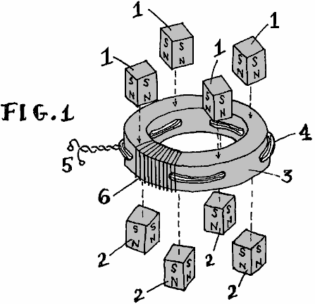
Fig.1 is an exploded view of the generator of this invention.
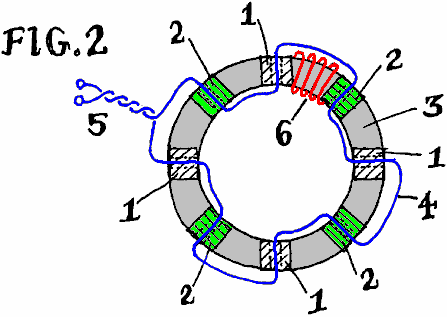
Fig.2 is a cross-sectional elevation of the generator of this invention.
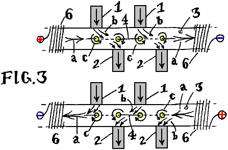
Fig.3 is a schematic diagram of the magnetic action occurring within the generator of Fig.1 and Fig.2.
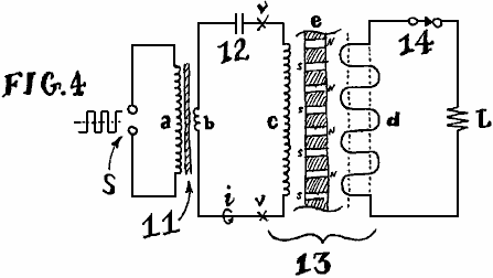
Fig.4 is a circuit diagram, illustrating one method of operating the electrical generator of this invention.
Detailed Description of the Invention
Fig.1 depicts a partially exploded view of an embodiment of an electrical generator of this invention. The part numbers also apply in Fig.2 and Fig.3.
Numeral 1 represents a permanent magnet with it’s North pole pointing inward towards the soft ferromagnetic core of the device. Similarly, numeral 2 indicates permanent magnets (preferably of the same size, shape and composition), with their South poles aimed inward towards the opposite side, or opposite surface of the device. The letters “S” and “N” denote these magnetic poles in the drawings. Other magnetic polarities and configurations may be used with success; the pattern shown merely illustrates one efficient method of adding magnets to the core.
The magnets may be formed of any polarised magnetic material. In order of descending effectiveness, the most desirable permanent magnet materials are Neodymium-Iron-Boron (“NIB”), Samarium Cobalt, AlNiCo alloy, or “ceramic” Strontium-Barium or Lead-Ferrite. A primary factor determining permanent magnet material composition is the magnetic flux strength of the particular material type. In an embodiment of the invention, these magnets may also be substituted with one or more electromagnets producing the required magnetic flux. In another embodiment of the invention, a superimposed DC current bias can be applied to the output wire to generate the required magnetic flux, replacing or augmenting the permanent magnets.
Numeral 3 indicates the magnetic core. This core is a critical component of the generator. The core determines the output power capacity, the optimum magnet type, the electrical impedance and the operating frequency range. The core may be any shape, composed of any ferromagnetic material, formed by any process (sintering, casting, adhesive bonding, tape-winding, etc.). A wide range of shapes, materials and processes is known in the art of making magnetic cores. Effective common materials include amorphous metal alloys (such as sold under the “Metglas” trademark by Metglas Inc., Conway, S.C.), nanocrystalline alloys, manganese and zinc ferrites as well as ferrites of any suitable element including any combination of magnetically “hard” and “soft” ferrites, powdered metals and ferromagnetic alloys, laminations of cobalt and/or iron and silicon-iron “electrical steel”. This invention successfully utilises any ferromagnetic material, while functioning as claimed. In an embodiment of the invention, and for the purpose of illustration, a circular “toroid” core is illustrated. In an embodiment of the invention, the composition may be bonded iron powder, commonly available from many manufacturers.
Regardless of core type, the core is prepared with holes, through which, wires may pass. the holes are drilled or formed to penetrate the core’s ferromagnetic volume. The toroidal core 3 shown, includes radial holes pointing towards a common centre. If, for example, stiff wire rods were to be inserted through each of these holes, these rods would meet at the centre point of the core, producing an appearance similar to a wheel with spokes. If a square or rectangular core (not illustrated) is used, then these holes are preferably oriented parallel to the core’s flat sides, causing stiff rods passed through the holes to form a square grid pattern, as the rods cross each other in the interior “window” area framed by the core. While in other embodiments of the invention, these holes may take any possible orientation or patterns of orientation, a simple row of radial holes is illustrated as one example.
Numeral 4 depicts a wire, or bundle of wires which pick up and carry the output power of the generator. Typically, this wire is composed of insulated copper, though other materials such as aluminium, iron, dielectric material, polymers and semiconducting materials may be substituted. It may be seen in Fig.1 and Fig.2, that wire 4 passes alternately through neighbouring holes formed in core 3. The path taken by wire 4 undulates as it passes in opposite direction through each adjacent hole. If an even number of holes is used, the wire will emerge on the same side of the core on which it first entered. Once all the holes are filled, the resulting pair of trailing leads may be twisted together or similarly terminated, forming the output terminals of the generator shown at numeral 5. Output wire 4, may also make multiple passes through each hole in the core. Though the winding pattern is not necessarily undulatory, this basic form is shown as an example. Many effective connection styles exist. This illustration shows the most simple.
Numeral 6 in Fig.1, Fig.2 and Fig.3, points to a partial illustration of the input winding, or inductive coil used to shift the fields of the permanent magnets, within the core. Typically, this wire coil encircles the core, wrapping around it. For the toroidal core shown, input coil 6 resembles the outer windings of a typical toroidal inductor - a common electrical component. For the sake of clarity, only a few turns of coil 6 are shown in each of Fig.1, Fig.2 and Fig.3. In practice, this coil may cover the entire core, or specific sections of the core, including, or not including the magnets.
Fig.2 shows the same electrical generator of Fig.1, looking transparently “down” through it from above, so that the relative positions of the core holes (shown as dotted lines), the path of the output wire 4, and the position of the magnets (white hatched areas for magnets under the core and green hatched areas for magnets above the core) are made clear. The few representative turns of the input coil 6 are shown in red in Fig.2.
The generator illustrated, uses a core with 8 radially drilled holes. The spacing between these holes is equal. As shown, each hole is displaced by 45 degrees from each of it’s adjoining holes. The centres of all of the holes lie on a common plane lying half-way down the vertical thickness of the core. Cores of any shape or size may have as few as two or as many as hundreds of holes and a similar number of magnets. Other variations exist, such as generators with multiple rows of holes, zigzag and diagonal patterns, or output wire 4 moulded directly into the core material. In any case, the basic magnetic interaction shown in Fig.3 occurs for each hole in the core as described below.
Fig.3 shows the same design, viewed from the side. The curvature of the core is shown flattened on the page for the purpose of illustration. The magnets are represented schematically, protruding from the top and bottom of the core, and including arrows indicating the direction of magnetic flux (the arrow heads point to the magnet’s North pole).
In practice, the free, unattached polar ends of the generator’s magnets may be left “as-is” in open air, or they may be provided with a common ferromagnetic path linking the unattached North and South poles together as a magnetic “ground”. The common return path is typically made of steel, iron or similar material, taking the form of a ferrous enclosure housing the device. It may serve the additional purpose of a protecting chassis. The magnetic return may also be another ferromagnetic core of a similar electric generator stacked on top of the illustrated generator. There can be a stack of generators, sharing common magnets between the generator cores. Any such additions are without direct bearing on the functional principle of the generator itself, and have therefore been omitted from these illustrations.
Two example flux diagrams are shown in Fig.3. Each example is shown in a space between schematically depicted partial input coils 6. A positive or negative polarity marker indicates the direction of input current, applied through the input coil. This applied current produces “modulating” magnetic flux, which is used to synthesise apparent motion of the permanent magnets, and is shown as a double-tailed horizontal arrow (a) along the core 3. Each example shows this double-tailed arrow (a) pointing to the right or to the left, depending on the polarity of the applied current.
In either case, vertical flux entering the core (b,3) from the external permanent magnets (1,2) is swept along within the core, in the direction of the double-tailed arrow (a), representing the magnetic flux of the input coil. These curved arrows (b) in the space between the magnets and the holes, can be seen to shift or bend (a --> b), as if they were streams or jets of air subject to a changing wind.
The resulting sweeping motion of the fields of the permanent magnets, causes their flux (b) to brush back and forth over the holes and wire 4 which passes through these holes. Just as in a mechanical generator, when the magnetic flux brushes or “cuts” sideways across a conductor in this way, voltage is induced in the conductor. If an electrical load is connected across the ends of this wire conductor (numeral 5 in Fig.1 and Fig.2), a current flows through the load via this closed circuit, delivering electrical power able to perform work. Input of an alternating current across the input coil 6, generates an alternating magnetic field (a) causing the fields of permanent magnets 1 and 2 to shift (b) within the core 3, inducing electrical power through a load (attached to terminals 5), as if the fixed magnets (1,2) themselves were physically moving. However, no mechanical motion is present.
In a mechanical generator, induced current powering an electrical load, returns through output wire 4, creating a secondary induced magnetic field, exerting forces which substantially oppose the original magnetic field inducing the original EMF. Since load currents induce their own, secondary magnetic fields opposing the original act of induction in this way, the source of the original induction requires additional energy to restore itself and continue generating electricity. In mechanical generators, the energy-inducing motion of the generator’s magnetic fields is being physically actuated, requiring a strong prime mover (such as a steam turbine) to restore the EMF-generating magnetic fields’ motion against the braking effect of the output-induced magnetic fields (the induced field c and the inducing field b), destructively in mutual opposition, which must ultimately be overcome by physical force, which is commonly produced by the consumption of other energy resources.
The electrical generator of the present invention is not actuated by mechanical force. It makes use of the induced secondary magnetic field in such a way as to not cause opposition, but instead, addition and resulting acceleration of magnetic field motion. Because the present invention is not mechanically actuated, and because the magnetic fields do not act to destroy one another in mutual opposition, the present invention does not require the consumption of natural resources in order to generate electricity.
The present generator’s induced magnetic field, resulting from electrical current flowing through the load and returning through output wire 4, is that of a closed loop encircling each hole in the core. The induced magnetic fields create magnetic flux in the form of closed loops within the ferromagnetic core. The magnetic field “encircles” each hole in the core which carries output wire 4. This is similar to the threads of a screw “encircling” the shaft of the screw.
Within this generator, the magnetic field from output wire 4 immediately encircles each hole formed in the core (c). Since wire 4 may take an opposing direction through each neighbouring hole, the direction of the resulting magnetic field will likewise be opposite. The direction of arrows (b) and (c) are, at each hole, opposing, headed in opposite directions, since (b) is the inducing flux and (c) is the induced flux, each opposing one another while generating electricity.
However, this magnetic opposition is effectively directed against the permanent magnets which are injecting their flux into the core, but not the source of the alternating magnetic input field 6. In the present solid-state generator, induced output flux (4,c) is directed to oppose the permanent magnets (1,2) not the input flux source (6, a) which is synthesising the virtual motion of those magnets (1,2) by it’s magnetising action on core 3.
The present generator employs magnets as the source of motive pressure driving the generator, since they are the entity being opposed or “pushed against” by the opposing reaction induced by output current which is powering a load. Experiments show that high-quality permanent magnets can be magnetically “pushed against” in this way for very long periods of time, before becoming demagnetised or “spent”.
Fig.3 illustrates inducing representative flux arrows (b) directed oppositely against induced representative flux (c). In materials typically used to form core 3, fields flowing in mutually opposite directions tend to cancel each other, just as positive and negative numbers of equal magnitude sum to zero.
On the remaining side of each hole, opposite the permanent magnet, no mutual opposition takes place. Induced flux (c) caused by the generator load current remains present; however, inducing flux from the permanent magnets (b) is not present since no magnet is present, on this side, to provide the necessary flux. This leaves the induced flux (c) encircling the hole, as well as input flux (a) from the input coils 6, continuing its path along the core, on either side of each hole.
On the side of each hole in the core where a magnet is present, action (b) and reaction (c) magnetic flux substantially cancel each other, being directed in opposite directions within the core. On the other side of each hole, where no magnet is present, input flux (a) and reaction flux (c) share a common direction. Magnetic flux adds together in these zones, where induced magnetic flux (c) aids the input flux (a). This is the reverse of typical generator action, where induced flux (c) is typically opposing the “input” flux originating the induction.
Since the magnetic interaction is a combination of magnetic flux opposition and magnetic flux acceleration, there is no longer an overall magnetic braking or total opposition effect. The braking and opposition is counterbalanced by a simultaneous magnetic acceleration within the core. Since mechanical motion is absent, the equivalent electrical effect ranges from idling, or absence of opposition, to a strengthening and overall acceleration of the electrical input signal (within coils 6). proper selection of the permanent magnet (1,2) material and flux density, core 3 material magnetic characteristics, core hole pattern and spacing, and output medium connection technique, create embodiments where the present generator will display an absence of electrical loading at the input and/or an overall amplification of the input signal. This ultimately causes less input energy to be required in order to work the generator. Therefore, as increasing amounts of energy are withdrawn from the generator as output power performing useful work, decreasing amounts of energy are generally required to operate it. This process continues, working against the permanent magnets (1,2) until they are demagnetised.
In an embodiment of this invention, Fig.4 illustrates a typical operating circuit employing the generator of this invention. A square-wave input signal from a transistor switching circuit, is applied at the input terminals (S), to the primary (a) of a step-down transformer 11. The secondary winding (b) of the input transformer may be a single turn, in series with a capacitor 12 and the generator 13 input coil (c), forming a series resonant circuit. The frequency of the applied square wave (S) must either match, or be an integral sub-harmonic of the resonant frequency of this 3-element transformer-capacitor-inductor input circuit.
Generator 13 output winding (d) is connected to resistive load L through switch 14. When switch 14 is closed, generated power is dissipated at L, which is any resistive load, for example, and incandescent lamp or resistive heater.
Once input resonance is achieved, and the square-wave frequency applied at S is such that the combined reactive impedance of total inductance (b + c) is equal in magnitude to the opposing reactive impedance of capacitance 12, the electrical phases of current through, and voltage across, generator 13 input coil (c) will flow 90 degrees apart in resonant quadrature. Power drawn from the square-wave input energy source applied to S will now be at a minimum.
In this condition, the resonant energy present at the generator input may be measured by connecting a voltage probe across the test points (v), situated across the generator input coil, together with a current probe around point (I), situated in series with the generator input coil (c). The instantaneous vector product of these two measurements indicates the energy circulating at the generator’s input, ultimately shifting the permanent magnets’ fields in order to create useful induction. This situation persists until the magnets are no longer magnetised.
It will be apparent to those skilled in the art that a square (or other) wave may be applied directly to the generator input terminals (c) without the use of other components. While this remains effective, advantageous re-generating effects may not be realised to their fullest extent with such direct excitation. Use of a resonant circuit, particularly with inclusion of a capacitor 12 as suggested, facilitates recirculation of energy within the input circuit, generally producing efficient excitation and a reduction of the required input power as loads are applied.
Mike
Brady’s “Perendev” Magnet Motor
Patent Application WO 2006/045333 A1 4th May 2006 Inventor Mike Brady
PERMANENT MAGNET MACHINE
ABSTRACT
The invention provides a magnetic repellent motor which comprises: a shaft (26) which can rotate around it's longitudinal axis, a first set (16) of magnets (14) arranged around the shaft (26) in a rotor (10) for rotation with the shaft, and a second set (42) of magnets (40) arranged in a stator (32) surrounding the rotor. The second set of magnets interacts with the first set of magnets, and the magnets of both sets are at least partially screened so as to concentrate their magnetic field strength in the direction of the gap between the rotor (10) and the stator (32).
BACKGROUND
This invention relates to a magnetic repellent motor, or drive mechanism. Such a mechanism may be useful for driving an electrical generator, a vehicle, a ship, an aircraft, or the like.
Conventional power sources rely on fossil fuels or secondary power sources such as nuclear power, or electricity derived by whatever means, for its source of driving power. All of these sources of power suffer from disadvantages such as being the cause of pollution, requiring transportation or transmission over long distances to the point of use, and being costly to purchase. Thus, there is a need for a power source which is substantially pollution-free in operation, requiring substantially no external power, and which is simple to maintain.
SUMMARY
This invention provides a magnetic repellent motor which comprises: a shaft which can rotate about its longitudinal axis, a first set of magnets which are arranged around the shaft and which rotate with the shaft, and a second set of magnets arranged in a stator surrounding the rotor, where the second set of magnets reacts with the first set of magnets, both sets being partially screen magnetically in order to direct their magnetic field into a gap between the two sets of magnets. Thus, the interaction of at least some of the magnets of the first and second sets urge the shaft to rotate.
The interaction may be the net force of like magnetic poles repelling each other thereby urging the magnets away from each other, however, since only the rotor magnets can be moved by this urging force, the shaft is urged to rotate into a position where the repelling force is less.
The rotor may be substantially disc-shaped and the first set of magnets may be located in a peripheral region of the rotor which rotates with the shaft. The stator may be in the form of a pair of arms aligned with the rotor. These stator arms can be moved relative to each other and away from the rotor, in order to allow the gap between the rotor and the stator to be set selectively. The gap may be set manually, for example, by a hand wheel, or automatically, for example by a system of weights which move centrifugally and so form a rotational speed control which acts automatically, i.e. the smaller the gap, the greater the repulsion forces between the magnets of the rotor and stator.
Both the rotor and the stator may have more than one set of magnets. The magnets may be placed in sockets which extend towards the circumference of the rotor. These sockets may be substantially cylindrical and arranged in a plane which is perpendicular to the longitudinal axis of the rotor shaft. These sockets may also be arranged at an acute angle relative to the tangent to the circumference of the rotor disc where the mouth of the cylindrical socket is located. Similarly, the stator magnet sockets may be angled relative to the inner circumference of the stator. These angles may be between 18 degrees and 40 degrees, but preferably between 30 degrees and 35 degrees.
These sockets may have a socket lining consisting at least partially of a magnetic screening material. The socket lining may line the entire extent of the sockets so that only the opening to the exterior remains unlined. In another embodiment of the invention, the magnetic screen lining may cover a substantial percentage of the whole of the socket lining, e.g. 50% of the socket lining.
The magnets may be Nd-Fe-B of dimensions which fit snugly inside the linings of the sockets. These magnets may be cylindrical in shape and have a 37 mm diameter, a 75 mm length and a magnetic strength of 360,000 gauss. The socket lining, magnetic shield and magnet may all have a hole through them to receive a securing pin, preferably positioned so that it is parallel to the longitudinal axis of the shaft.
The number of sockets in the rotor and the corresponding stator may differ so that there is not a one-to-one relationship between the sockets in the rotor and the sockets in the corresponding stator. Similarly, the number of magnets in any additional rotor/stator sets may differ from the first rotor/stator sets in order that the two sets are out of register at any given time. Some sockets may be left empty in either the rotor or the corresponding stator, or both. The motor may have one or more rotor/stator pairs of this type arranged in a stack. It is preferable for the magnets of adjacent rotors to be out of register, i.e. staggered or offset relative to each other.
DESCRIPTION
OF THE DRAWINGS
Fig.1 is a perspective view which shows one rotor disc.
Fig.2 is a perspective view showing a stack of the Fig.1 rotors in an assembled arrangement.
Fig.3 is a perspective view showing a left arm of a stator.
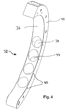
Fig.4 is a perspective view showing a right arm of a stator
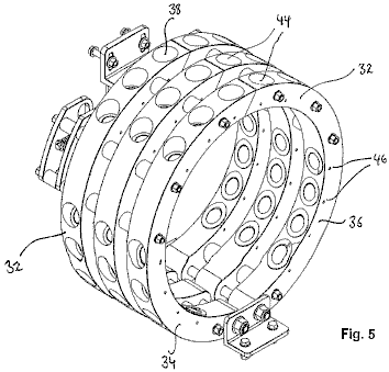
Fig.5 is a perspective view showing a stack of the stators or Fig.3 and Fig.4 in an assembled arrangement.
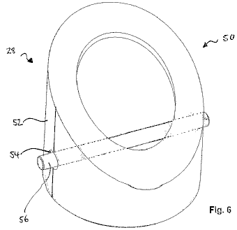
Fig.6 is a perspective view showing a socket lining of a stator or a rotor.
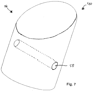
Fig.7 is a perspective view showing one of the magnets.

Fig.8 is a perspective view showing one embodiment of the magnetic repellent motor coupled to an electrical generator.
DESCRIPTION
OF PREFERRED EMBODIMENTS
Referring to Fig.1, a substantially disc-shaped rotor 10, is made from a non-magnetic material. The rotor 10 has a plurality of magnet receiving zones 12, provided in it for receiving magnets 28 (shown in later figures)

of a first set 16 of magnets. The receiving zones 12 are in the form of circumferentially extending, spaced apart, and substantially cylindrical sockets 18 which are located in a plane which is perpendicular to the rotational axis 10 of the rotor and in a peripheral region of the disc.
In the region of the sockets 18, the rotor 10 also has through holes 20 in it's side surfaces 22, extending parallel to the rotational axis of the rotor. The rotor 10, also has a centre hole 24, to receive shaft 28 which is shown in later figures. The sockets 18, are preferably angled at an acute angle relative to the tangent to the circumference of the rotor disc 10, at the mouth opening of the sockets 18. Ideally, this angle is between 18 and 40 degrees, and preferably between 30 and 35 degrees. In one particularly preferred embodiment, the angle is 34 degrees.
As shown in Fig.2, the sockets 18, receive (or incorporate) a socket lining 28 (shown in more detail in later figures) which is at least partially made of a magnetic screening material, whether metallic or non-metallic, for example, graphite. The socket lining 28, covers the entire extent of the sockets 18, so that only the opening to the exterior remains uncovered.
In the rotor assembly 30 of Fig.2, three rotors discs 10, have been stacked in a row on the shaft 26. The connection between the rotor discs 10 and shaft 26, as well as between the rotor discs themselves, can be established via linking means which are widely known. In general, the motor may have any number of rotor discs 10, and corresponding stators 32, since the effect of using several rotor discs 10 in parallel, is cumulative. However, it may be useful for smooth operation of the motor 1, to arrange the rotor discs 10 so that the magnets of adjacent rotor discs are staggered, or offset relative to each other.
Referring to Fig.3 and Fig.4, a stator 32 is shown. This stator is made of a non-magnetic material. The left arm 34, and the right arm 36, combine to form the stator 32. Each of the arms, 34 and 36, has a substantially semi-circular shape and is sized so as to enclose the corresponding rotor disc 10 in the radial direction, while still leaving a gap between the stator 32 and the rotor disc 10. The arms 34 and 36 of one stator 32, can be moved relative to each other and their corresponding rotor disc 10, so that the gap between the arms and the rotor disc can be set at different values.
The stator 32 has several magnet receiving zones 38, ready to accept the magnets 40, (which are shown in a later figure) of the magnet set 42. These receiving zones are again in the form of circumferentially extending, substantially cylindrical sockets 44 which are positioned in a plane which is perpendicular to the longitudinal axis of shaft 26. In the region of the sockets 44, the stator 32 has through holes 46 arranged in it's side surfaces 48, these holes extending parallel to the longitudinal axis of the shaft 26.
These sockets 44 are again angled at an acute angle relative to a tangent to the inner circumference of the stator 32 at the mouth opening of the sockets 44. This angle is preferably between 18 and 40 degrees and more preferably, between 30 and 35 degrees. The angle of the sockets 18 and 44, and the relative positioning between them, has to be adjusted to allow for a good performance of the motor.
Fig.5 shows a stator assembly consisting of three stators designed to fit the rotor assembly of Fig.2. As described with reference to the sockets 18 of Fig.2, the sockets 44 receive (or incorporate) a socket lining 50 (shown in more detail in later figures), which is at least partially made of a magnetic screening material. The socket lining 50, covers the entire extent of the sockets 44 so that only the opening to the exterior remains uncovered.

Referring to Fig.6, a socket lining 28, 50 of the rotor disc 10, or the stator 32, is shown in more detail. The socket lining 28, 50 is formed to fit into the sockets 18, 44 and may be made completely of a material which has magnetic screening properties. In one preferred embodiment, the socket lining 28, 50 is made of diamagnetic graphite and is partially surrounded by an additional shield 52 of a material having strong magnetic screening properties, e.g. stainless steel. In the embodiment shown in Fig.6, the shield 52 surrounds about 50% of the socket lining surface.
Thus, by at least partially covering the sockets 18, 44 with a magnetic screening material, the magnetic field of the inserted magnets 14, 40 is, so to say, focussed axially with the socket 18, 44, rather than dissipated about the magnets.
Further, holes 54 through the socket linings 28, 50 are provided and these correspond to the through-holes 20 and 46 in the rotor disc 10 and the stator 32, respectively. Thus, a retaining pin 56 may be inserted after magnet 14, 40 has been put in socket 18, 44 to make a detachable fixing for magnet 14, 40 to the socket lining 28, 50 and the socket 18, 44 so as to prevent expulsion of the magnetic sources during operation.
Fig.7 shows a typical magnetic source 14,40 used in this motor design. The magnetic sources 18, 40 may be natural magnets, induced magnets or electromagnets. The magnetic source for example, is a Nd-fe-B magnet which has the necessary dimensions needed to fit neatly into socket 18, 44 and socket lining 28, 50, respectively. In one preferred embodiment, the magnetic source 18, 44 is a substantially cylindrically shaped magnet with a diameter of 37 mm, a length of 75 mm and provides 360,000 gauss. However, the magnetic source 18, 44 may be shaped differently to cylindrical and may have different characteristics. In any case, the magnetic source 18, 44 must have a through-hole 58 to receive the retaining pin 56.
The magnet motor shown in Fig.8 is mounted on frame 60 and is coupled to an electrical generator 62. In this specific embodiment, the motor has three rotor discs 10 of the type already described. These are mounted on a single rotating shaft 26 and are driven by three stators 32, as already described, causing shaft 26 to rotate about it's longitudinal axis. Shaft 26 may be connected to a gearbox in order to gain a mechanical advantage. The stator arms can be moved by a stepper motor 64.
The number of sockets in the rotor discs 10 and their corresponding stators 32 may differ so that there is not a one-to-one relationship between the sockets 18 in the rotor disc 10 and sockets 44 in the corresponding stator 32. Similarly, the number of magnetic sources in the stator 32 and the rotor disc 10 may differ so that a proportion of the magnetic sources 14, 40 are out of register at any given time. Some sockets may be empty, i.e. without a magnetic source, in either the rotor disc 10 or the stator 32, or both.
The sockets 18 of the rotor discs 10 can be staggered, i.e. offset relative to the sockets of adjacent rotors, or they can line up in register. Thus, the magnet motor may be time-tuned by the relative positioning of the magnetic sources 14 of adjacent rotor discs 10.
Thus, the interaction of at least some of the magnetic sources 14, 40 of the first and second set 16, 42 urges the shaft 26 to rotate. Once the shaft begins to rotate, the plurality of simultaneous interactions causes shaft 26 to continue rotating.
As mentioned before, the motor can have any number rotor discs 10 and corresponding stator sets 32. Although the precise adjustment of the motor elements is important, one may imagine other embodiments covered by this invention.
The Magnet
Motor of Donald A. Kelly
Patent US 4,179,633 18th December 1979 Inventor: Donald A. Kelly
MAGNETIC
ABSTRACT
This permanent magnet disc drive consists of two basic magnetic components, one large driven flat disc containing a uniform series of identical magnet segments, and a second magnetic driving means comprising multiple oscillating magnetic pairs of opposite identical magnet segments. The magnetic mechanism simulates the action of a clock escapement mechanism in that the oscillating magnet pairs uniformly oscillate between the disc magnet segments to induce continuous disc rotation. All of the multiple oscillating magnet pairs are oscillated by a motor, or motors, which provide an eccentric movement through a suitable gear reduction unit. The small DC motors are powered by multiple arrays of silicon solar photovoltaic cells at some convenient rooftop location.
4,082,969 Magnetic torque converter April, 1978 Kelly 310/103
4,100,441 Magnetic transmission July, 1978 Landery 310/103
BACKGROUND
OF THE INVENTION
At the present time the magnetic disc drive has reached the stage of development where the oscillating magnet pairs will rotate the magnetic segmented disc when the oscillations is done manually. The disc rotation is smooth and continuous when the manual oscillation is uniform and continuous, and the disc speed may be increased as the oscillation rate is increased.
Since the adequate functioning of the magnetic/mechanical-conversion concept has now been proven with a working prototype, a practical and economical self and/or external oscillation means for the oscillating magnetic pairs must now be developed. The magnetic disc drive was originally designed to be self-actuated by means of a multi-lobe cam and push rod arrangement, but this approach has not been proven successful to date.
A disadvantage for the self-actuated type of magnetic disc drive is that the disc is locked-in with a low, fixed speed output which is dependant on the natural magnetic field interaction between the involved interacting magnet segments.
A mid-diameter direct displacement multi-lobe cam was used for the first prototype, but this did not work because of the high rotational resistance imposed by the high cam lobe angles. A peripheral, direct displacement multi-lobe cam was also tried but this was not successful because of the moderate and sufficient cam lobe resistance to push rod displacement.
Other cam lobe configurations are being planned and developed to make sure that no possible trade-off to self-actuated mechanical oscillation is overlooked. Another possible approach to self-actuation for the magnetic disc drive is by the application of a twin level magnetic commutator which is directly connected to the disc drive shaft. The magnetic commutator segments alternately attract corresponding radial magnets on pull-rods which are pivoted on each of the oscillation plates of the magnetic pairs.
While auto-actuation of the magnetic disc units may be desirable for some self-contained power applications, the low, fixed speed output is not considered attractive and promising for a wide range of household power applications. Because of the inflexibility of speed output of the auto-actuated type of unit the, the development of a variable speed, externally oscillated type of disc unit is required to meet the growing demand for alternate and auxiliary power means for many applications.
The matching of a large magnetic disc drive and small solar powered DC electric motors is a nearly ideal arrangement since a single or series of small precision DC motors can be readily powered by modest arrays of silicon photovoltaic cells located at some convenient rooftop location. Small high-efficiency, ball bearing DC motors are available which, when connected to suitable gear reduction drives, can revolve a simple eccentric mechanism with sufficient power and variable speed, to cause oscillation of a series of four to six magnetic oscillating pairs of stator magnets.
This series of magnetic oscillating pairs will all be connected together with straight linkage to transmit the reciprocating motion from the driving oscillating shaft to the other oscillating shafts of the series. This is a more desirable multiple driving arrangement rather than separate small DC motors since synchronism is automatically assured, rather than more complex and less reliable electrical synchronization requirements. Because there is no locked-in synchronism for this type of external oscillation means, the multiple magnetic oscillation pairs must be of the minimum interference type, in that they must not become jammed into the disc magnet segments. Although the proper functioning of the magnetic disc unit requires that the oscillating magnet pairs must enter the disc's magnet segment interference circle, deflection means must be added to all of the oscillation plates to insure that the continuously revolving disc will readily by-pass all of the oscillating magnet pairs.
The large magnetic disc unit will consist of a basic non-magnetic circular disc, on which multiple high energy permanent magnet segments are equally spaced around the rim of the disc. The drive shaft of the disc rotates on precision ball-bearings and may be chosen to revolve in either a horizontal or a vertical plane. The disc is the driven component of the magnetic drive assembly, and it can be connected to the load or an electrical generator.
The multiple oscillating magnet pairs are the driving component of the disc drive unit and consist of flat, non-magnetic oscillation plates, on which identical high-energy permanent magnets are secured at each end of these oscillating plates. The magnet segments are placed with opposite poles exposed at the sides, relative to each other so that a north-south pole couple reacts on the disc's magnet segments. The driven disc's direction of rotation depends on the polarity of the disc's magnets in relation to the oscillating magnetic pairs.
The oscillating magnetic pairs will make a full back and forth oscillation between two adjacent local disc magnet segments so that an alternate "pull and push" effect is induced on the magnetic segmented disc. The basic synchronism between the disc's magnet segments and the multiple oscillating magnet pairs closely simulates the action of a watch or clock escapement mechanism in respect to the natural "cogging" action between the functioning components.
This general magnetic disc drive arrangement insures smooth and continuous rotation for the driven disc with an optimum of magnetic energy interchange between the oscillation stations and the magnetic disc because of near pole face to pole face exposure. It is now believed that this present type of magnetic disc drive is approaching a theoretical maximum of conversion performance possible, especially when compared with other types of magnetic/mechanical arrangements such as magnetic worm and worm discs, spur couples, mitre couples, and all types of inferior, linear magnetic devices.
The attractiveness of the basic magnetic disc and oscillating pairs is that a nearly ideal leverage factor is introduced in magnetic/mechanical conversion arrangements. Simply stated, considerably less energy is needed to oscillate the oscillating pairs than is produced from the near pole face to pole face magnetic interaction between the functioning magnetic components.
The alternating and uniform "pull and push" force imposed by the oscillating magnet pairs on the disc magnet segments produces no direct back or counter force reaction on the driving oscillating magnet segments which is the master key for a useful and practical magnetic/mechanical conversion drive. The back or counter-reacting force on the oscillating magnet pairs is taken directly by the fixed pivots of the oscillation plates, with a minimum of load penalty imposed on the drive of the oscillating magnet pairs.
All other types of rotary magnetic/mechanical conversion devices, with the possible exception of the worm and worm disc type, produce an undesirable back reaction force on the driving component and resulting ineffective performance. The magnetic worm and worm disc units have not proven to be sufficiently worthwhile for commercial applications because of the very high permanent magnetic energy necessary and due to the low speed output of these mechanisms.
When configuration comparisons are made of all types of possible magnetic/mechanical conversion devices it will be noted that the combination of a magnetic disc driven by multiple oscillating magnet pairs will stand out as a practical and useful permanent magnetic conversion arrangement. The incentive for the development of this magnetic disc drive was the direct outgrowth of overall disappointing performance of solar energy conversion efforts and the frustrations encountered with component costs, conversion efficiency and a lack of suitable energy storage means. While solar energy is being widely hailed for its future potential as a viable alternate energy source, relatively few engineers speak out about relatively poor overall cost/effectiveness due to days-on-end of overcast skies during the winter months when the energy is most needed, especially in northern latitudes.
Because of the less-than-adequate solar energy conversion outlook for the vast majority of American homeowners, other alternate, small scale, decentralised, energy sources must be explored and developed on a crash program basis. If this is not done within the next several decades we must accept the alternative of a greatly reduced standard of living because of the alarming rise in the rate of energy costs.
This magnetic disc drive represents a practical solution in applying permanent magnetism in the development and commercialism of a decentralised, silent, fuel-free, household-sized alternate power system. While the power output from an individual magnetic disc unit may be small, the power output is constant and does not generally depend on the intensity of an external energy source, as do present solar energy systems.
SUMMARY OF
THE INVENTION
The magnetic disc drive unit is comprised of a large driving disc made of non-magnetic metal on which several permanent magnets are equally spaced around the rim. The disc drive shaft rotates on trunnion supported ball bearings and may revolve in nearly any conventional position, and may be constructed with any practical large diameter.
The identical oscillating magnet pairs are the driving component of the disc drive and consist of flat, non-magnetic plates on which, pairs of identical permanent magnets are secured at both sides of the oscillation plates. These magnet pairs have opposite pole faces facing each other. The disc's direction of rotation is determined by the polarity of all the disc's magnets relative to the polarity of the oscillating magnet pairs.
The oscillating pair of magnets make a full back and forth oscillation while each rotor disc magnet passes by. This produces a pull on the disc magnet as it approaches the oscillator magnet and then when the oscillator moves that magnet away, a push force is applied to the magnet on the rotating disc by the second magnet of the oscillating pair of magnets. The synchronisation of the disc and the oscillating magnet pairs must be maintained for continuous and smooth rotation of the disc. This movement is similar to the action of a clock escapement-mechanism.
The method of moving the oscillating pairs of magnets is one or more solar-powered DC motors. These motors drive push rods which are in contact with ball bearings mounted on the oscillation plates. Since the eccentrics must move at relatively slow speeds, suitable gear reduction units must be used between the motors and the rocker arms.
In order to maintain proper synchronisation of all of the oscillating components, straight links are used to connect all of the driven oscillation shafts to the driving oscillation shaft. Four or five oscillation stations can be driven from one driver oscillation shaft so that a disc drive with a large number of oscillation stations will require several D.C. motors to drive all of the other oscillation shafts.
It is important that the multiple, identical oscillation plates and their magnet pairs be slightly shorter in width than the space between two adjacent disc magnet segments, so that an optimum pull and push force is induced on the local disc magnet segments. One side of the oscillating magnet couple "pulls" on the disc's permanent magnet and then the other oscillator magnet "pushes" the disc's permanent magnet onwards as it has been moved into place by the oscillation.
All of the oscillating magnet pairs oscillate on stationary rods, or shafts, and all of the eccentrics and DC motor drives remain fixed on a base plate. The other ends of the oscillating rods or shafts must be supported by some form of bracket to keep the oscillation plates parallel to the disc magnet segments. Each eccentric which moves a ball bearing attached to arms on the oscillation plates must make one full 360 degree revolution within the angular displacement arc between two adjacent rotor disc magnet segments. Two small pivot brackets are attached to the extreme, non-magnetic ends of the oscillation plates to allow these plates to oscillate freely with a minimum of friction.
The basic rotational relationship between the magnetic oscillating pairs, and the magnetic segmented disc, will have a bearing on the gear reduction ratio required for the gear drive unit coupled to the small DC motors. Fairly rapid oscillation is necessary to maintain a reasonably acceptable disc speed which will be required for most power applications. The size of the eccentrics which oscillate the oscillating magnet pairs will be determined by the full oscillating arc needed and the mechanical advantage required by the oscillation plate in order to cause the optimum rotation of the magnetic disc drive unit.
Proper magnetic disc drive functioning requires the pulling magnets of the oscillating magnet pairs to enter the disc's interference circle within the mutual magnetic field zone between the two local interacting magnets on the disc's rim. Since the disc will revolve continuously, the withdrawing phase of the "pulling" magnets brings the "pushing" magnets of the couple into the disc's interference circle within the mutual magnetic field zone, for effective interaction with the adjacent disc magnet segment.
All of the magnet segments on the oscillation plates which form the magnetic couples must be in line with the corresponding disc magnet segments in order to maintain an optimum interaction between them.
Because there is no natural, lock-in synchronism for this type of magnetic disc drive, the multiple magnetic oscillating magnet pairs must be of the minimum interference type, which consists of adding plastic deflectors to the oscillation plates to prevent the pulling magnets of the couple from jamming into the disc magnet segments. Since the oscillating magnet pairs must never jam into the disc and stop its rotation, the plastic deflectors will allow the oscillation plates and magnet pairs to be deflected away from all of the disc magnet segments.
The permanent magnets selected for both components of the disc drive must be uniformly identical and have the highest possible energy product or magnetic induction plus coercivity. Both of these magnetic properties will play a significant role in determining the true value of the magnetic disc drive unit. At the present time the rare-earth/cobalt permanent magnets offer the highest possible magnetic properties for this application, but their cost is very high and currently not considered cost effective for the magnetic disc drive. Since costs will also play a major role in the competitive value of the disc drive, the magnets selected must show the highest possible cost/effectiveness ratio, along with long operating life.
Rectangular ceramic permanent magnets with large flat pole faces are preferred for the disc drive prototypes, and there is no theoretical limit to the size of both interacting components. A practical limit to the actual size of the components is imposed by weight and material cost restrictions plus available space, but nearly any practical number and size of uniformly identical magnets may be used to make up the magnetic disc drive.
It will be advantageous to build up each disc magnet station into clusters of up to about twelve to twenty four individual magnets which are arranged in lengths of four or five units and double or triple widths depending on the disc diameter. A large diameter disc unit is always desirable since the torque output for the disc unit depends on the tangential magnetic force produced by all of the oscillating magnet couple stations multiplied by the disc radius.
The large diameter disc speed will be relatively slow, in the 20 to 30 r.p.m. range, so that the disc output speed must be stepped up to a useful 750 to 1200 r.p.m. speed range, by a belt drive arrangement. The magnetic disc drive output is best adapted to run an electrical generator or alternator to produce electrical power for various household purposes.
An advantage to using silicon photovoltaic solar cells on an exposed rooftop location as a power source, is that they are capable of providing a partial E.M.F. under non-sunlight/overcast sky conditions. With full sunlight exposure the electrical energy produced will run the magnetic disc drive at its maximum possible speed, with reduced sunlight levels producing a corresponding proportionate reduction in the disc output speed.
A workable option exists for using a greater number of silicon photocells than would be normally necessary for full sunlight operation. The number of cells selected would be capable of running the magnetic disc drive at full speed under overcast sky conditions, with any excess full sunlight current bypassed to storage batteries. This option is a desirable arrangement since the disc will be assured of full electrical input power each day, with battery power available to make up the loss from any dark daytime sky conditions.
The principal object of the invention is to provide the highest torque output for the large driven disc from the lowest possible torque input for the multiple oscillating magnet pairs, as a useful power step-up means for electrical generating applications.
Another object of the invention is to provide a step-up power source which can be produced at competitive costs, requires no combustible fuel and is non-polluting while running silently and continuously.
It is a further object of the invention to provide a natural energy source which has an extremely long operating life, with a maximum of operating effectiveness, component resistance to degradation, with a minimum of parts replacement and maintenance.
The various features of the invention with its basic design geometry will be more apparent from the following description and drawings which illustrate the preferred embodiment. It should be understood that variations may be made in the specific components, without departing from the spirit and scope of the invention as described and illustrated.
Referring to
the Drawings:
Fig.1 is a top, external view of the magnetic disc drive.
Fig.2 is an external side view of the magnetic disc drive.
Fig.3 is an enlarged top view of one oscillating magnet couple.
Fig.4 is a top, break-away view of several oscillating magnet pairs connected together with linkage.
DESCRIPTION
OF THE PREFERRED EMBODIMENT
The invention 1, is comprised of two basic components: a large driven disc 2, and multiple oscillating magnet pairs 3, which are closely interrelated and mounted on a common base plate 4.
Multiple, identical permanent magnets 2a, are equally spaced around the periphery of the large driven disc 2, by means of support angles 2b, and angle brackets 2c, which are secured to the disc 2, with standard hardware.
A drive shaft 5, is fastened to the disc 2, by means of a hub 2d, and supported by two ball bearings 6. One of the ball bearings 6, is fitted into a bore within the base plate 4, while the other ball bearing 6, is fitted into a box-base 7, which is fastened to the base plate 4, with standard hardware.
The multiple oscillating magnet pairs 3, are a flat, non-magnetic plate 3a, with opposite pole magnet segments 3b and 3c, respectively, attached to the side of the flat oscillation plate 3a. Two pivot brackets 3d, are attached to the top and bottom of the flat plate 3a, which pivot the oscillation plate 3a, on the pivot rod 8. One end of the pivot rod 8, is fitted into the base plate 4, and the opposite end is supported by an elongated Z-shaped bracket 8a.

An arm 9, is fastened to a flat face of the flat plate 3a, which supports the pin 10a, which carries the ball bearing 10, as it rolls on the eccentric disc 11. The off-centre disc 11, is fastened to the slow speed shaft of the gear reduction unit 12, which is driven by the small DC motor 13. A return tension spring 14, is connected to the oscillation plate 3a, by eyelet 3e. The opposite end of the return tension spring 14, is retained by the post 15, which is pressed into the base plate 4. Motors 13, are powered by multiple arrays of silicon photovoltaic solar cells 16. Electrical leads 16a, conduct solar converted electricity to the motors 13, with any excess current stored in the batteries 16b.
The motor driven oscillation stations become the master stations for this invention 1, from which three to five slave oscillation stations are driven. The reciprocating motion is transmitted by straight links 17, which are pinned to the link arms 18, which in turn are secured to the flat plates 3a.
All of the slave oscillation stations must be precisely adjusted to exactly the same angular position as the master driving oscillation station so that all stations are synchronised to allow proper functioning of the rotating disc 2.
For very large discs 2, with many disc magnets, several master oscillation stations, with a fixed number of slave oscillation stations will be required. All of the master oscillation driving-stations will have to be electrically synchronised to maintain overall synchronisation, with all of the eccentrics 11, set at the same angle at start-up of the disc.
Either end of the drive shaft 5, may be connected with a speed step-up belt drive arrangement, which is not shown here.
Plastic deflectors 19, are added to either side of the oscillation plates 3a, adjacent to the opposite magnets segments 3b, and 3c, their exact position depending on the direction of rotation of disc 2. These act as an anti-jamming device for the magnets.
Magnetic field bias angles 3f and 3g (Fig.3), are required for the sides of plates 3a, in order to assure an optimum "pull-push" sequence on the large drive disc 2, as the magnetic oscillation pairs 3, are actuated. The bias angle 3f, is matched to the magnet segment 3b, while bias angle 3g is matched to magnet segment 3c.
None of the load components which are external to the device, such as an electric generator or alternator, are shown as a part of this invention, since a variety of load devices and arrangements are possible for the magnetic disc drive.
Bob Neal’s
Compressed Air Engine
US Patent 2,030,759 11th Feb. 1936 Inventor:
Bob Neal
COMPRESSOR UNIT
This invention relates to the construction of a compressor, and more particularly to a combined fluid-operated engine and compressor.
The primary object of the invention, is the provision of a compressor of this character, wherein there is arranged an automatically counterbalanced crankshaft and fluid equalisers within a storage tank, which makes it possible for the engine to operate on constant reserve tank pressure, so as to actuate additional equipment, the pistons for the engine also being automatically balanced and suspended when the engine is operating.
Another object of the invention is the provision of an engine which is operated by air under pressure, the air being supplied by compressors which are in a bank with the engine construction.
A further object of this invention is the provision of an engine of this type of novel construction as the engine and the compressors are operated from the same crankshaft, which is of the automatically balanced type, so that high efficiency is attained.
A still further object of the invention is the provision of an engine of this character which is comparatively simple in construction, thoroughly reliable and efficient in its operation, strong, durable, and inexpensive to manufacture.
With these and other objects in view, the invention consists in the features of construction, combination and arrangement of parts as will be described more fully here, illustrated in the accompanying drawings which disclose the preferred embodiment of the invention, and pointed out in the appended Claim.
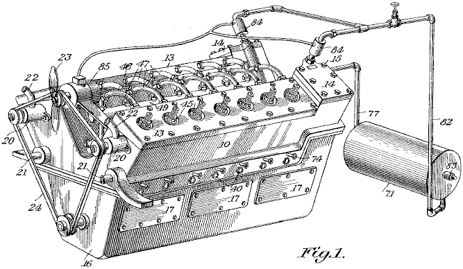
In the drawings, Fig.1 is a perspective view of the engine constructed in accordance with the invention.
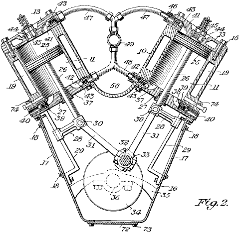
Fig.2 is a vertical transverse cross-section view through the compressor part of the engine.
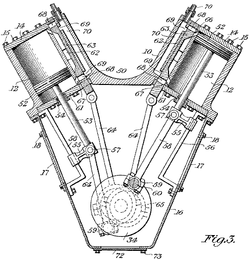
Fig.3 is a vertical cross-sectional view through the power part of the engine.
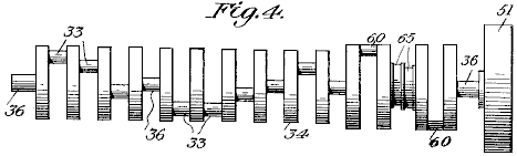
Fig.4 is a detail elevation of the crankshaft of the engine.
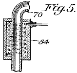
Fig.5 is an enlarged cross-sectional view through one of the electric heaters for the engine.
Fig.6 is a vertical, longitudinal, cross-sectional view through the air storage tank, including the equaliser.
The same reference numbers are used for each individual part in every view in every drawing.

Referring to the drawings in detail, the engine in its entirety, composes a cylinder block 10 having inside it, the series of compressor cylinders 11 and the power cylinders 12. The block 10 is of the V-type and the upper ends of the cylinders are closed off by the removable heads 13 and 14 which are held in place by conventional head bolts 15. Beneath block 10 is the crank case 16, which has detachable plates 17 at opposite sides, held in place by fasteners 18, and seated so as to be leak proof. The block 10 is chambered to provide a water jacket 19 surrounding the cylinders, while at the forward end of the block are water pumps 20, circulating water through the inlet pipe 21 which leads into the jacket and the water exits from the jacket through the outlet pipe 22. Beside the pumps 20, is a fan 23 which is operated from the same belt 24 which drives the pumps.
Working inside the cylinders 11,are the reciprocating pistons 25, their rods 26 sliding through packing glands 27 and fixed to crossheads 28 which slide on their mounting guides 29 which are secured to the walls of the crank case 16. These crossheads 28 are fitted with wrist pins 30, forming a pivoting connection with the connecting rods 31, which are connected to their cranks 33 by their bearings 32. The cranks 33 form part of a counter balanced crankshaft 34, which is mounted in supports 35 attached to the crank case 16, the shaft being provided with the required bearings 36.
The inner ends of the cylinders 11 are fitted with inner end heads 37, which are provided with air intake ports 38 fitted with spring ball inlet checks 39, the air entering through passages 40 which open outside the block 10. Glands 27 are mounted in the heads 37.
The heads 13 and 37 are provided with the compressed air outlets 41 and 42, which are fitted with spring ball checks 43. The heads 13 are also provided with the central air inlets 44, which are fitted with spring checks 45. Couplings 46 attach the air outlets 41 and 42 to their outlet feed pipes 47 and 48. These pipes lead to a main conduit 49 which is located in the centre channel 50 of the block 10.
At the rear end of the block 10, mounted on shaft 36, there is a conventional flywheel 51.
Working inside the cylinders 12 are the pistons 52, with their piston rods 53 sliding through packing glands 54 and fixed in crossheads 55 which slide along their mounting guides 56, mounted on the inner walls of the crank case 16. The crossheads 55 have wrist pins 57 which provide a pivoting joint for the connecting rods 58 which are connected by their bearings 59 to their cranks 60 of the crank shaft 34, the inner ends of the cylinders 12 being closed by the inner heads 61 and their associated glands 54.
On the cylinders 12 are slide valve chests 62 in which are the slide valves 63, these being operated by throw rods 64 actuated by cams 65 and the valves controlling the admission and exhaust of air into and out of the cylinders 12, through the ports 66 and 67, and these valves 63 are provided with ports 68 for the delivery of air under pressure from the inlet passages 69 common to a pipe 70 coming from a compressed air storage tank 71.
The bottom of the crank case 16 is fitted with a removable plate 72 which is secured in place by fasteners 73, and when this plate is removed, it provides access to the crank shaft 34 and the bearings for the engine, as well as other parts inside the crank case.
Leading into the cylinders 11 are the passages 74 of a lubricating system (not shown). The compressed air storage tank 71 has inside it a double-check discharge nozzle 75, supported by member 76. Leading to this equaliser is an air inlet pipe 77 which connects through its valved section 78 to the compressed air reservoir 79. In the equaliser 75, are the spaced spring ball checks 80 and 81, one being for the inlet side and the other for the outlet side of the equaliser. This pipe 77 is connected with the main conduit 49, while a pipe 82 connects to pipe 70. The tank is also fitted with an automatic relief valve 83 and this valve can be of any approved type.
Placed around the pipes 70 which connect to the air passages 69 (Fig.3) are electric heating units 84 to heat the pressurised air to above freezing temperature when delivered from tank 71 to the cylinders 12. Supported on the block 10 is an electric generator 85 which is driven from the shaft 34 (Fig.2) through a belt 24 (Fig.1) and this generator is included in an electric circuit which also has the heaters 84 so that these will operate from current supplied by the generator.
The compressed air storage tank 71 with the equaliser is constructed so that it is possible to pump air into it while it contains an air pressure of 200 pounds per square inch while the compressors are only pumping against 15 pounds per square inch of (atmospheric) pressure. An outside air pressure source can be coupled with the tank to augment that pressure derived from the cylinders 11 of the engine.
Leroy K.
Rogers’ Compressed Air Engine
Patent US 4,292,804 6th October 1980 Inventor: Leroy K. Rogers
METHOD AND APPARATUS FOR OPERATING
AN ENGINE ON COMPRESSED GAS
ABSTRACT
The present invention relates to a method and apparatus for operating an engine having a cylinder containing a reciprocating piston driven by a compressed gas. The apparatus comprises a source of compressed gas connected to a distributor which conveys the compressed gas to the cylinder. A valve is provided to admit compressed gas to the cylinder when the piston is in an approximately Top Dead Centre position.
In one embodiment of the present invention, the timing of the opening of the valve is advanced so that the compressed gas is admitted to the cylinder progressively further before the Top Dead Centre position of the piston as the speed of the engine increases.
In a further embodiment of the present invention, a valve actuator is provided which increases the length of time over which the valve remains open to admit compressed gas to the cylinder as the speed of the engine increases.
A still further embodiment of the present invention relates to an apparatus for adapting a conventional internal combustion engine for operation on compressed gas.
3,881,399 May., 1975 Sagi et al. 91/187.
3,885,387 May., 1975 Simington 60/407.
4,018,050 Apr., 1977 Murphy 60/412.
DESCRIPTION
BACKGROUND AND SUMMARY OF THE PRESENT INVENTION
The present invention is a method and apparatus for operating an engine using a compressed gas as the motive fluid. More particularly, the present invention relates to a apparatus for adapting a pre-existing internal combustion engine for operation on a compressed gas.
Air pollution is one of the most serious problems facing the world today. One of the major contributors to air pollution is the ordinary internal combustion engine which is used in most motor vehicles today. Various devices, including many items required by legislation, have been proposed in an attempt to limit the pollutants which an internal combustion engine exhausts to the air. However, most of these devices have met with limited success and are often both prohibitively expensive and complex. A clean alternative to the internal combustion engine is needed to power vehicles and other machinery.
A compressed gas, preferably air, would provide an ideal motive fluid for an engine, since it would eliminate the usual pollutants exhausted from an internal combustion engine. An apparatus for converting an internal combustion engine for operation on compressed air is disclosed in U.S. Pat. No. 3,885,387 issued May 27, 1975 to Simington. The Simington patent discloses an apparatus including a source of compressed air and a rotating valve actuator which opens and closes a plurality of mechanical poppet valves. The valves deliver compressed air in timed sequence to the cylinders of an engine through adapters located in the spark plug holes. However, the output speed of an engine of this type is limited by the speed of the mechanical valves and the fact that the length of time over which each of the valves remains open cannot be varied as the speed of the engine increases.
Another apparatus for converting an internal combustion engine for operation on steam or compressed air is disclosed in U.S. Pat. No. 4,102,130 issued July 25, 1978 to Stricklin. The Stricklin patent discloses a device which changes the valve timing of a conventional four stroke engine such that the intake and exhaust valves open once for every revolution of the engine instead of once every other revolution of the engine. A reversing valve is provided which delivers live steam or compressed air to the intake valves and is subsequently reversed to allow the exhaust valves to deliver the expanded steam or air to the atmosphere. A reversing valve of this type however does not provide a reliable apparatus for varying the amount of motive fluid injected into the cylinders when it is desired to increase the speed of the engine. Further, a device of the type disclosed in the Stricklin patent requires the use of multiple reversing valves if the cylinders in a multi-cylinder engine were to be fired sequentially.
Therefore, it is an object of the present invention to provide a reliable method and apparatus for operating an engine or converting an engine for operation with a compressed gas.
A further object of the present invention is to provide a method and apparatus which is effective to deliver a constantly increasing amount of compressed gas to an engine as the speed of the engine increases.
A still further object of the present invention is to provide a method and apparatus which will operate an engine using compressed gas at a speed sufficient to drive a conventional automobile at highway speeds.
It is still a further object of the present invention to provide a method and apparatus which is readily adaptable to a standard internal combustion engine, to convert the internal combustion engine for operation with a compressed gas.
Another object of the invention is to provide a method and apparatus which utilises cool expanded gas, exhausted from a compressed gas engine, to operate an air-conditioning unit and/or an oil-cooler.
These and other objects are realised by the method and apparatus of the present invention for operating an engine having at least one cylinder containing a reciprocating piston and using compressed gas as the motive fluid. The apparatus includes a source of compressed gas, a distributor connected it for conveying the compressed gas to the cylinder or cylinders. A valve is provided for admitting the compressed gas to the cylinder when the piston is in an approximately Top Dead Centre position within the cylinder. An exhaust is provided for exhausting the expanded gas from the cylinder as the piston returns to approximately the Top Dead Centre position.
In a preferred embodiment of the present invention, a device is provided for varying the duration of each engine cycle over which the valve remains open to admit compressed gas to the cylinder, dependent upon the speed of the engine. In a further preferred embodiment of the present invention, an apparatus for advancing the timing of the opening of the valve is arranged to admit the compressed gas to the cylinder progressively further and further before the Top Dead Centre position of the piston, as the speed of the engine increases.
Further features of the present invention include a valve for controlling the amount of compressed gas admitted to the distributor. Also, a portion of the gas which has been expanded in the cylinder and exhausted through the exhaust valve, is delivered to a compressor to be compressed again and returned to the source of compressed gas. A gear train can be engaged to drive the compressor selectively at different operating speeds, depending upon the pressure maintained at the source of compressed air and/or the speed of the engine. Still further, a second portion of the exhaust gas is used to cool a lubricating fluid for the engine or to operate an air-conditioning unit.
In a preferred embodiment of the present invention, the valve for admitting compressed gas to the cylinder is operated electrically. The device for varying the duration of each engine cycle, over which the intake valve remains open, as the speed of the engine increases, comprises a rotating element whose effective length increases as the speed of the engine increases, causing a first contact on the rotating element to be electrically connected to a second contact on the rotating element, for a longer period of each engine cycle. The second contact operates the valve causing it to remain in an open position for a longer period of each engine cycle, as the speed of the engine increases.
Still further features of the present invention include an adaptor plate for supporting the distributor above the intake manifold of a conventional internal combustion engine after a carburettor has been removed to allow air to enter the cylinders of the engine through the intake manifold and conventional intake valves. Another adaptor plate is arranged over an exhaust passageway of the internal combustion engine to reduce the cross-sectional area of the exhaust passageway.
BRIEF
DESCRIPTION OF THE DRAWINGS
Preferred embodiments of a method and apparatus for operating an engine according to the present invention will be described with reference to the accompanying drawings in which components have the same reference numbers in each drawing.
Fig.1 is a schematic representation of an apparatus according to the present invention arranged on an engine:
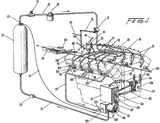
Fig.2 is a side view of one embodiment of a valve actuator according to the present invention.
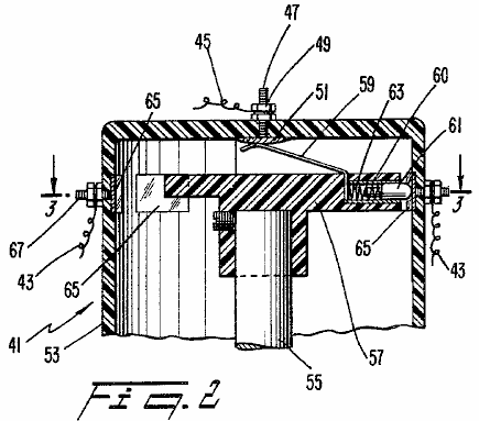
Fig.3 is a cross-sectional view taken along the line 3--3 in Fig.2.
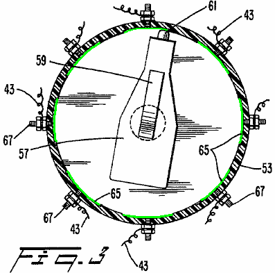
Fig.4 is a cross-sectional view of a second embodiment of a valve actuator according to the present invention.
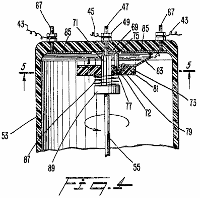
Fig.5 is a view taken along the line 5--5 in Fig.4.
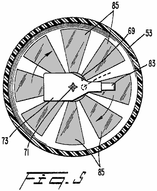
Fig.6 is a cross-sectional view of a third embodiment of a valve actuator according to the present invention;
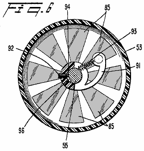
Fig.7 is a view taken along the line 7--7 in Fig.6.

Fig.8 is a cross-sectional view of a gearing unit to drive a compressor according to the present invention.

DETAILED DESCRIPTION OF THE PREFERRED EMBODIMENTS
With reference to Fig.1, an engine block 21 (shown in phantom) having two banks of cylinders with each bank including cylinders 20 having pistons 22 which reciprocate in them in a conventional manner (only one of which is shown in phantom). While the illustrated engine is a V-8 engine, it will be apparent that the present invention is applicable to an engine having any number of pistons and cylinders with the V-8 engine being utilised for illustration purposes only. A compressed gas tank 23 is provided to store a compressed gas at high pressure. It may also be desirable to include a small electric or gas compressor to provide compressed gas to supplement the compressed gas held in the tank 23. In a preferred embodiment, the compressed gas is air which can be obtained from any suitable source.

A line 25 transports the gas withdrawn from the tank 23 when a conventional shut-off valve 27 is open. In addition, a solenoid valve 29 preferably operated by a suitable key-operated engine switch (not shown) is also placed in the line 25. In normal operation, the valve 27 is maintained open at all times with the solenoid valve 29 operating as a selective shut off valve to start and stop the engine 21.
A suitable regulating valve 31 is arranged downstream of the solenoid valve 29 and is connected by a linkage 33 to a throttle linkage 35 which is operator-actuated by any suitable apparatus such as a foot pedal (not shown). The line 25 enters an end of a distributor 33 and is connected to an end of a pipe 35 which is closed at the other end. A plurality of holes, which are equal to the number of cylinders in the engine 21, are provided on either side of the pipe 35 along the length of the pipe 35.
When the present invention is used to adapt a conventional internal combustion engine for operation on compressed gas, an adaptor plate 36 is provided to support the distributor 33 in spaced relation from the usual intake opening in the intake manifold of the engine after a conventional carburettor has been removed. In this way, air is permitted to enter the internal combustion engine through the usual passageways and to be admitted to the cylinders through suitable intake valves (not shown). The adaptor plate 36 is attached to the engine block 21 and the distributor 33 by any suitable apparatus, e.g., bolts.
Each of the holes in the pipe 35 is connected in fluid-tight manner to a single line 37. Each line 37 carries the compressed gas to a single cylinder 20. In a preferred embodiment, each of the lines 37 is 1/2 inch high pressure plastic tubing attached through suitable connectors to the distributor 33 and the pipe 35. Each of the lines 37 is connected to a valve 39 which is secured in an opening provided near the top of each of the cylinders 20. In the case of a conversion of a standard internal combustion engine, the valves 39 can be conveniently screwed into a tapped hole in the cylinder 20 typically provided for a spark plug of the internal combustion engine. In a preferred embodiment, the valves 39 are solenoid actuated valves in order to provide a fast and reliable opening and closing of the valves 39.
Each of the valves 39 is energised by a valve actuator 41 through one of a plurality of wires 43. The valve actuator 41 is driven by a shaft of the engine similar to the drive for a conventional distributor of an internal combustion engine. That is, a shaft 55 of the valve actuator 41 is driven in synchronism with the engine 21 at one half the speed of the engine 21.
A first embodiment of the valve actuator 41 (Fig.2 and Fig.3), receives electrical power through a wire 45 which is energised in a suitable manner by a battery, and a coil if necessary (not shown) as is conventional in an internal combustion engine. The wire 45 is attached to a central post 47 by a nut 49. The post 47 is connected to a conducting plate 51 arranged in a housing 53 for the valve actuator 41. Within the housing 53, the shaft 55 has an insulating element 57 secured to an end of the shaft 55 and rotates with it when the shaft 55 is driven by the engine 21. A first end of a flexible contact 59 is continuously biased against the conducting plate 51 to receive electricity from the battery or other suitable source. The other end of the contact 59 is connected to a conducting sleeve 60 which is in constant contact with a spring biased contact 61 which is arranged within the sleeve 60. The contact 61 is pressed by a spring 63 which pushes contact 61 towards a side wall of the housing 53.
With reference to Fig.3, a plurality of contacts 65 are spaced from one another and are arranged around the periphery of the housing 53 at the same level as the spring biased contact 61. Each contact 65 is electrically connected to a post 67 which extends outside of the housing 53. The number of contacts 65 is equal to the number of cylinders in the engine 21. One of the wires 43, which actuate the valves 39, is secured to each of the posts 67.
In operation, as the shaft 55 rotates in synchronism with the engine 21, the insulating element 57 rotates and electricity is ultimately delivered to successive pairs of the contacts 65 and wires 43 through the spring loaded contact 61 and the flexible contact 59. In this way, each of the electrical valves 39 is activated and opened in the proper timed sequence to admit compressed gas to each of the cylinders 20 to drive the pistons 22 on a downward stroke.
The embodiment illustrated in Fig.2 and Fig.3 is effective in causing each of the valves 39 to remain open for a long enough period of time to admit sufficient compressed gas to each of the cylinders 20 of the engine 21 to drive the engine 21. The length of each of the contacts 65 around the periphery of the housing 53 is sufficient to permit the speed of the engine to be increased when desired by the operator by moving the throttle linkage 35 which actuates the linkage 33 to further open the regulating valve 31 to admit more compressed gas from the tank 23 to the distributor 33. However, it has been found that the amount of air admitted by the valves 39 when using the first embodiment of the valve actuator 41 (Fig.2 and Fig.3) is substantially more than required to operate the engine 21 at an idling speed. Therefore, it may be desirable to provide a valve actuator 41 which is capable of varying the duration of each engine cycle over which the solenoid valves 39 are actuated, i.e., remain open to admit compressed gas, as the speed of the engine 21 is varied.
A second embodiment of a valve actuator 41 which is capable of varying the duration of each engine cycle over which each of the valves 39 remains open to admit compressed gas to the cylinders 20 dependent upon the speed of the engine 21 will be described with reference to Fig.4 and Fig.5 wherein members corresponding to those of Fig.2 and Fig.3 bear like reference numbers. The wire 45 from the electricity source is attached to the post 47 by the nut 49. The post 47 has a annular contact ring 69 electrically connected to an end of the post 47 and arranged within the housing 53. The shaft 55 rotates at one half the speed of the engine as in the embodiment of Fig.2 and Fig.3.
At an upper end of the shaft 55, a splined section 71 receives a sliding insulating member 73. The splined section 71 of the shaft 55 holds the insulating member 73 securely as it rotates with shaft 55 but permits the insulating member 73 to slide axially along the length of the splined section 71. Near the shaft 55, a conductive sleeve 72 is arranged in a bore 81 in an upper surface of the insulating element 73 generally parallel to the splined section 71. A contact 75, biased towards the annular contact ring 69 by a spring 77, is arranged within the conductive sleeve 72 and in contact with it. The conductive sleeve 72 also contacts a conductor 79 at a base of the bore 81.
The conductor 79 extends to the upper surface of the insulating element 73 near an outer periphery of the insulating element 73 where the conductor 79 is electrically connected to a flexible contact 83. The flexible contact 83 connects, one after the other, with a series of radial contacts 85 which are positioned on an upper inside surface of the housing 53. A weak spring 87 arranged around the splined section 71 engages a stop member 89 secured on the shaft 55 and the insulating element 73 to slightly bias the insulating element 73 towards the upper inside surface of the housing 53 to ensure contact between the flexible contact 83 and the upper inside surface of the housing 53. As best seen in Fig.5, the radial contacts 85 on the upper inside surface of the housing 53 are arranged generally in the form of radial spokes extending from the centre of the housing 53 with the number of contacts being equal to the number of cylinders 20 in the engine 21. The number of degrees covered by each of the radial contacts 85 gradually increases as the distance from the centre of the upper inside surface of the housing 53 increases.
In operation of the device of Fig.4 and Fig.5, as the shaft 55 rotates, electricity flows along a path through the wire 45 down through post 47 to the annular contact member 69 which is in constant contact with the spring biased contact 75. The electrical current passes through the conductive sleeve 72 to the conductor 79 and then to the flexible contact 83. As the flexible contact 83 rotates along with the insulating member 73 and the shaft 55, the tip of the flexible contact 83 successively engages each of the radial contacts 85 on the upper inside of the housing 53. As the speed of the shaft 55 increases, the insulating member 73 and the flexible contact 83 attached to it, move upwards along the splined section 71 of the shaft 55 due to the radial component of the splines in the direction of rotation under the influence of centrifugal force. As the insulating member 73 moves upwards, the flexible contact 83 is bent so that the tip of the contact 83 extends further outwards radially from the centre of the housing 53 (as seen in phantom lines in Fig.4). In other words, the effective length of the flexible contact 83 increases as the speed of the engine 21 increases.
As the flexible contact 83 is bent and the tip of the contact 83 moves outwards, the tip remains in contact with each of the radial contacts 85 for a longer period of each engine cycle due to the increased angular width of the radial contacts with increasing distance from the centre of the housing 53. In this way, the length of time over which each of the valves 39 remains open is increased as the speed of the engine is increased. Thus, a larger quantity of compressed gas or air is injected into the cylinders as the speed increases. Conversely, as the speed decreases and the insulating member 73 moves downwards along the splined section 71, a minimum quantity of air is injected into the cylinder due to the shorter length of the individual radial contact 85 which is in contact with the flexible contact 83. In this way, the amount of compressed gas that is used during idling of the engine 21 is at a minimum whereas the amount of compressed gas which is required to increase the speed of the engine 21 to a level suitable to drive a vehicle on a highway is readily available.
Shown in Fig.6 and Fig.7, is a third embodiment of a valve actuator 41 according to the present invention. This embodiment includes a curved insulating element 91 having it’s first end able to pivot, being secured by any suitable device such as screw 92 to the shaft 55 for co-rotation with the shaft 55. The screw 92 is screwed into a tapped hole in the insulating element 91 so that a tab 94 at an end of the screw 92 engages a groove 96 provided in the shaft 55. In this way, the insulating element 91 rotates positively with the shaft 55. However, as the shaft 55 rotates faster, the other end 98 of the insulating element 91 is permitted to pivot outwards under the influence of centrifugal force because of the groove 96 provided in the shaft 55. A spring 93, connected between the second end 98 of the element 91 and the shaft 55 urges the second end of the element 91 towards the centre of the housing 53.
A contact 99 similar to the contact 59 (Fig.2) is arranged so that one end of the contact piece 99 is in constant contact with the conducting plate 51 located centrally within the housing 53. The other end of the contact 99 engages a conductive sleeve 101 arranged in bore 102. A contact element 95 is arranged in the conductive sleeve 101 in constant contact with the sleeve 101. The bore 102 is arranged generally parallel to the shaft 55 near the second end of the curved insulating element 91. The contact 95 is biased by a spring 97 towards the upper inside surface of the housing 53 for selective contact with each of the plurality of radial contacts 85 which increase in arc length towards the outer peripheral surface of the housing 53 (Fig.6).
When the device shown in Fig.6 and Fig.7 is operating, as the shaft 55 rotates the curved insulating element 91 rotates with the shaft 55 and the second end 98 of the insulating element 91 tends to pivot about the shaft 55 due to centrifugal force. Thus, as the effective length of the contact 95 increases, i.e., as the curved insulating element 91 pivots further outwards, the number of degrees of rotation over which the contact 95 is in contact with each of the radial contacts 85 on the upper inside surface of the housing 53 increases thereby allowing each of the valves 39 to remain open for a longer period of each engine cycle, which in turn, allows more compressed gas enter the respective cylinder 20 to further increase the speed of the engine 21.
With reference to Fig.1, a mechanical advance linkage 104 which is connected to the throttle linkage 35, advances the initiation of the opening of each valve 39 such that compressed gas is injected into the respective cylinder further before the piston 22 in the respective cylinder 20 reaches a Top Dead Centre position as the speed of the engine is increased by moving the throttle linkage 35. The advance linkage 104 is similar to a conventional standard mechanical advance employed on an internal combustion engine. In other words, the linkage 104 varies the relationship between the angular positions of a point on the shaft 55 and a point on the housing 53 containing the contacts. Alternatively, a conventional vacuum advance could also be employed. By advancing the timing of the opening of the valves 39, the speed of the engine can more easily be increased.
The operation of the engine cycle according to the present invention will now be described. The compressed gas injected into each cylinder of the engine 21 drives the respective piston 22 downwards to rotate a conventional crankshaft (not shown). The movement of the piston downwards causes the compressed gas to expand rapidly and cool. As the piston 22 begins to move upwards in the cylinder 20 a suitable exhaust valve (not shown), arranged to close an exhaust passageway, is opened by any suitable apparatus. The expanded gas is then expelled through the exhaust passageway. As the piston 22 begins to move downwards again, a suitable intake valve opens to admit ambient air to the cylinder. The intake valve closes and the ambient air is compressed on the subsequent upward movement of the piston until the piston reaches approximately the Top Dead Centre position at which time the compressed gas is again injected into the cylinder 20 to drive the piston 22 downwards and the cycle begins again.
In the case of adapting a conventional internal combustion engine for operation on compressed gas, a plurality of plates 103 are arranged, preferably over an end of the exhaust passageways, in order to reduce the outlet size of the exhaust passageways of the conventional internal combustion engine. In the illustrated embodiment, a single plate having an opening in the centre is bolted to the outside exhaust passageway on each bank of the V-8 engine, while another single plate having two openings in it, is arranged with one opening over each of the interior exhaust passageways on each bank of the V-8 engine. A line 105 is suitably attached to each of the adaptor plates to carry the exhaust to an appropriate location. In a preferred embodiment, the exhaust lines 105 are made from 1.5" plastic tubing.
In a preferred embodiment, the exhaust lines 105 of one bank of the V-8 engine are collected in a line 107 and fed to an inlet of a compressor 109. The pressure of the exhaust gas emanating from the engine 21 according to the present invention is approximately 25 p.s.i. In this way, the compressor 109 does not have to pull the exhaust into the compressor since the gas exhausted from the engine 21 is at a positive pressure. The positive pressure of the incoming fluid increases the efficiency and reduces wear on the compressor 109. The exhaust gas is compressed in the compressor 109 and returned through a line 111 and a check valve 113 to the compressed gas storage tank 23. The check valve 113 prevents the flow of compressed gas stored in the tank 23 back towards the compressor 109.
A suitable pressure sensor 115 is arranged at an upper end of the tank 23 and sends a signal along a line 117 when the pressure exceeds a predetermined level and when the pressure drops below a predetermined level. The line 117 controls an electrically activated clutch 119 positioned at the front end of the compressor 109. The clutch 119 is operated to engage and disengage the compressor 109 from a drive pulley 121. Also, the signal carried by the line 117 activates a suitable valve 123 arranged on compressor housing 125 to exhaust the air entering the compressor housing 125 from the line 107 when the clutch 119 has disengaged the compressor 109 from the drive pulley 121.
In a preferred embodiment, when the pressure is the tank 23 reaches approximately 600 p.s.i., the clutch 119 is disengaged and the compressor 109 is deactivated and the valve 123 is opened to exhaust the expanded gas delivered to the compressor 109 from the line 107 to the atmosphere. When the pressure within the tank 23 drops below approximately 500 p.s.i., the sensor 115 sends a signal to engage the clutch 119 and close the valve 123, thereby operating the compressor 109 for supplying the tank 23 with compressed gas.
The pulley 121 which drives the compressor 109 through the clutch 119 is driven by a belt 127 which is driven by a pulley 129 which operates through a gear
In normal
operation (as seen in Fig.8), the
first gear 141 engages a third gear 145 arranged on a shaft 147 which drives the pulley 129.
The shafts 140 and 147 are arranged in suitable bearings 149 positioned at each end of it. When the speed of the engine 21 drops below a predetermined level, a
suitable sensor 151 responsive to
the speed of the drive shaft 139 of
the engine 21 generates a signal
which is transmitted through a line 153
to a solenoid actuator 155 arranged
within the gear
In this way, when the speed of the engine 21 drops below the predetermined level as sensed by the sensor 151 (which predetermined level is insufficient to drive the compressor 109 at a speed sufficient to generate the 500-600 pounds of pressure which is preferably in the tank 23), the solenoid actuator 155 is energised to slide the gears 143, 141 axially along the splined shaft 140 so that the second, larger gear 143 engages the fourth, smaller gear 157 to drive the pulley 129 and hence the compressor 109 at a higher rate, to generate the desired pressure. When the speed of the engine increases above the predetermined level, which, in a preferred embodiment is approximately 1500 rpm, the solenoid actuator 155 is deactivated by the sensor 151 thereby moving the gears 143 and 141 to the left as seen in Fig.8 so that the first gear 141, engages again with the third gear 145 to effectuate a 1 to 1 ratio between the output shaft 139 of the engine 21 and the pulley 129.
The other bank of the V-8 engine has its exhaust ports arranged with adapter plates 103 similar to those on the first bank. However, the exhaust from this bank of the engine 21 is not collected and circulated through the compressor 109. In a preferred embodiment, a portion of the exhaust is collected in a line 159 and fed to an enlarged chamber 161. A second fluid is fed through a line 163 into the chamber 161 to be cooled by the cool exhaust emanating from the engine 21 in the line 159. The second fluid in the line 163 may be either transmission fluid contained in a transmission associated with the engine 21 or a portion of the oil used to lubricate the engine 21. A second portion of the exhaust from the second bank of the V-8 engine is removed from the line 159 in a line 165 and used as a working fluid in an air conditioning system or for any other suitable use.
It should be noted that the particular arrangement utilised for collecting and distributing the gas exhausted from the engine 21 would be determined by the use for which the engine is employed. In other words, it may be advantageous to rearrange the exhaust tubing such that a larger or smaller percentage of the exhaust is routed through the compressor 109. It should also be noted that since the exhaust lines 105 are plastic tubing, a rearrangement of the lines for a different purpose is both simple and inexpensive.
In operation of the engine of the present invention, the engine 21 is started by energising the solenoid valve 29 and any suitable starting device (not shown), e.g., a conventional electric starter as used on an internal combustion engine. Compressed gas from the full tank 23 flows through the line 25 and a variable amount of the compressed gas is admitted to the distributor 33 by controlling the regulator valve 31 through the linkage 33 and the operator actuated throttle linkage 35. The compressed gas is distributed to each of the lines 37 which lead to the individual cylinders 20. The compressed gas is admitted to each of the cylinders 20 in timed relationship to the position of the pistons within the cylinders by opening the valves 39 with the valve actuator 41.
When it is desired to increase the speed of the engine, the operator moves the throttle linkage 35 which simultaneously admits a larger quantity of compressed gas to the distributor 33 from the tank 23 by further opening the regulator valve 31. The timing of the valve actuator 41 is also advanced through the linkage 104. Still further, as the speed of the engine 21 increases, the effective length of the rotating contact 83 (Fig.4) or 95 (Fig.6) increases thereby electrically contacting a wider portion of one of the stationary radial contacts 85 to cause each of the valves 39 to remain open for a longer period of each engine cycle to admit a larger quantity of compressed gas to each of the cylinders 20.
As can be seen, the combination of the regulating valve 31, the mechanical advance 104, and the valve actuator 41, combine to produce a compressed gas engine which is quickly and efficiently adaptable to various operating speeds. However, all three of the controls need not be employed simultaneously. For example, the mechanical advance 104 could be utilised without the benefit of one of the varying valve actuators 41 but the high speed operation of the engine may not be as efficient. By increasing the duration of each engine cycle over which each of the valves 39 remains open to admit compressed gas to each of the cylinders 20 as the speed increases, conservation of compressed gas during low speed operation and efficient high speed operation are both possible.
After the compressed gas admitted to the cylinder 20 has forced the piston 22 downwards within the cylinder to drive the shaft 139 of the engine, the piston 22 moves upwards within the cylinder 20 and forces the expanded gas out through a suitable exhaust valve (not shown) through the adapter plate 103 (if employed) and into the exhaust line 105. The cool exhaust can then be collected in any suitable arrangement to be compressed and returned to the tank 23 or used for any desired purpose including use as a working fluid in an air conditioning system or as a coolant for oil.
When using the apparatus and method of the present invention to adapt a ordinary internal combustion engine for operation with compressed gas it can be seen that considerable savings in weight are achieved. For example, the ordinary cooling system including a radiator, fan, hoses, etc. can be eliminated since the compressed gas is cooled as it expands in the cylinder. In addition, there are no explosions within the cylinder to generate heat. Further reductions in weight are obtained by employing plastic tubing for the lines which carry the compressed gas between the distributor and the cylinders and for the exhaust lines. Once again, heavy tubing is not required since there is little or no heat generated by the engine of the present invention. In addition, the noise generated by an engine according to the present invention is considerably less than that generated by an ordinary internal combustion engine since there are no explosions taking place within the cylinders.
The principles of preferred embodiments of the present invention have been described in the foregoing specification. However, the invention which is intended to be protected is not to be construed as limited to the particular embodiments disclosed. The embodiments are to be regarded as illustrative rather than restrictive. Variations and changes may be made by others without departing from the spirit of the invention. Accordingly, it is expressly intended that all such variations and changes which fall within the spirit and the scope of the present invention as defined in the appended claims be embraced thereby.
Eber Van
Valkinburg’s Compressed Fluid Engine
Patent US 3,744,252 10th July 1973 Inventor: Eber Van Valkinburg
CLOSED MOTIVE POWER SYSTEM
UTILISING COMPRESSED FLUIDS
ABSTRACT
Stored energy in a compressed elastic fluid is utilised in a controlled manner to pressurise an inelastic fluid and to maintain such pressurisation. The pressurised inelastic fluid is throttled to the impeller of a prime mover. Only a portion of the output energy from the prime mover is utilised to circulate the inelastic fluid so as to maintain a nearly constant volumetric balance in the system.
DESCRIPTION
The objective of the invention is to provide a closed-loop power system which utilises the expansive energy of a compressed elastic fluid, such as air, to pressurise and maintain pressurised throughout the operational cycle of the system a second non-elastic and non-compressible fluid, such as oil. The pressurised non-elastic fluid is released in a controlled manner by a throttle to the rotary impeller of a turbine or the like, having an output shaft. This shaft is coupled to a pump for the non-elastic fluid which automatically maintains the necessary circulation needed for the operation of the prime mover, and maintains a near volumetric balance in the system between the two fluids which are separated by self-adjusting free piston devices. The pump for the non-elastic fluid includes an automatic by-pass for the non-elastic fluid which eliminates the possibility of starving the pump which depends on the discharge of the non-elastic fluid at low pressure from the exhaust of the turbine. Other features and advantages of the invention will become apparent during the course of the following detailed description.
BRIEF
DESCRIPTION OF DRAWING FIGURES
Fig.1 is a partly schematic cross-sectional view of a closed motive power system embodying the invention.
Fig.2 is a fragmentary perspective view of a rotary prime mover utilised in the system.
Fig.3 is an enlarged fragmentary vertical section through the prime mover taken at right angles to its rotational axis.
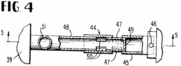
Fig.4 is an enlarged fragmentary vertical section taken on line 4--4 of Fig.1.
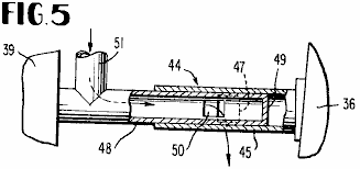
Fig.5 is a similar section taken on line 5--5 of Fig.4.
DETAILED
DESCRIPTION
Referring to the drawings in detail, in which the same numbers refer to the same parts in each drawing, the numeral 10 designates a supply bottle or tank for a compressed elastic fluid, such as air. Preferably, the air in the bottle 10 is compressed to approximately 1,500 p.s.i. The compressed air from the bottle 10 is delivered through a suitable pressure regulating valve 11 to the chamber 12 of a high pressure tank 13 on one side of a free piston 14 in the bore of such tank. The free piston 14 separates the chamber 12 for compressed air from a second chamber 15 for an inelastic fluid, such as oil, on the opposite side of the free piston. The free piston 14 can move axially within the bore of the cylindrical tank 13 and is constantly self-adjusting there to maintain a proper volumetric balance between the two separated fluids of the system. The free piston has the ability to maintain the two fluids, air and oil, completely separated during the operation of the system.
The regulator valve 11 delivers compressed air to the chamber 12 under a pressure of approximately 500 p.s.i. The working inelastic fluid, oil, which fills the chamber 15 of high pressure tank 13 is maintained under 500 p.s.i. pressure by the expansive force of the elastic compressed air in the chamber 12 on the free piston 14. The oil in the chamber 15 is delivered to a prime mover 16, such as an oil turbine, through a suitable supply regulating or throttle valve 17 which controls the volume of pressurised oil delivered to the prime mover.
The turbine 16 embodies a stator consisting of a casing ring 18 and end cover plates 19 joined to it in a fluid- tight manner. It further embodies a single or plural stage impeller or rotor having bladed wheels 20, 21 and 22 in the illustrated embodiment. The peripheral blades 23 of these turbine wheels receive the motive fluid from the pressurised chamber 15 through serially connected nozzles 24, 25 and 26, connected generally tangentially through the stator ring 18, as shown in Fig.3. The first nozzle 24 shown schematically in Fig.1 is connected directly with the outlet of the throttle valve 17. The successive nozzles 25 and 26 deliver the pressurised working fluid serially to the blades 23 of the turbine wheels 21 and 22, all of the turbine wheels being suitably coupled to a central axial output or working shaft 27 of the turbine 16.

Back-pressure sealing blocks 28, made of fibre, are contained within recesses 29 of casing ring 18 to prevent co-mingling of the working fluid and exhaust at each stage of the turbine. A back-pressure sealing block 28 is actually only required in the third stage between inlet 26 and exhaust 31, because of the pressure distribution, but such a block can be included in each stage as shown in Fig.1. The top surface, including a sloping face portion 30 on each block 28, reacts with the pressurised fluid to keep the fibre block sealed against the adjacent, bladed turbine wheel; and the longer the slope on the block to increase it’s top surface area, the greater will be the sealing pressure pushing it against the periphery of the wheel.
Leading from the final stage of the turbine 16 is a low-pressure working fluid exhaust nozzle 31 which delivers the working fluid, oil, into an oil supply chamber or reservoir 32 of a low pressure tank 33 which may be bolted to the adjacent end cover plate 19 of the turbine, as indicated at 34. The oil entering the reservoir chamber 32 from the exhaust stage of the turbine is at a pressure of about 3-5 p.s.i. In a second chamber 35 of the low pressure tank 33 separated from the chamber 32 by an automatically moving or self-adjusting free piston 36, compressed air at a balancing pressure of from 3-5 p.s.i. is maintained by a second pressure regulating valve 37. The pressure regulating valve 37 is connected with the compressed air supply line 38 which extends from the regulating valve 11 to the high pressure chamber 12 for compressed air.
Within the chamber 32 is a gear pump 39 or the like having its input shaft connected by a coupling 40 with the turbine shaft 27. Suitable reduction gearing 41 for the pump may be provided internally, as shown, or in any other conventional manner, to gear down the rotational speed derived from the turbine shaft. The pump 39 is supplied with the oil in the filled chamber 32 delivered by the exhaust nozzle or conduit 31 from the turbine. The pump, as illustrated, has twin outlet or delivery conduits 42 each having a back-pressure check valve 43 connected therein and each delivering a like volume of pressurised oil back to the high pressure chamber 15 at a pressure of about 500 p.s.i. The pump 39 also has twin fluid inlets. The pump employed is preferably of the type known on the market as "Hydreco Tandem Gear Pump," Model No. 151515, L12BL, or equivalent. In some models, other types of pumps could be employed including pumps having a single inlet and outlet. The illustrated pump will operate clockwise or counter-clockwise and will deliver 14.1 g.p.m. at 1,800 r.p.m. and 1,500 p.s.i. Therefore, in the present application of the pump 39, it will be operating at considerably less than capacity and will be under no undue stress.
Since the pump depends for its supply of fluid on the delivery of oil at low pressure from the turbine 16 into the chamber 32, an automatically operating by-pass sleeve valve device 44 for oil is provided as indicated in Fig.1, Fig.4 and Fig.5. This device comprises an exterior sleeve or tube 45 having one end directly rigidly secured as at 46 to the movable free piston 36. This sleeve 45 is provided with slots 47 intermediate its ends. A co-acting interior sleeve 48 engages telescopically and slidably within the sleeve 45 and has a closed end wall 49 and ports or slots 50 intermediate its ends, as shown. The sleeve 48 communicates with one of the delivery conduits 42 by way of an elbow 51, and the sleeve 48 is also connected with the adjacent end of the pump 39, as shown.
As long as the chamber 32 is filled with low pressure oil sufficient to balance the low air pressure in the chamber 35 on the opposite side of free piston 36, such piston will be positioned as shown in Fig.1 and Fig.4 so that the slots 47 and 50 of the two sleeves 45 and 48 are out of registration and therefore no flow path exists through them. Under such circumstances, the oil from the chamber 32 will enter the pump and will be delivered by the two conduits 42 at the required pressure to the chamber 15. Should the supply of oil from the turbine 16 to the chamber 32 diminish so that pump 39 might not be adequately supplied, then the resulting drop in pressure in the chamber 32 will cause the free piston 36 to move to the left in Fig.1 and bring the slots 47 into registration or partial registration with the slots 50, as depicted in Fig.5. This will instantly establish a by-pass for oil from one conduit 42 back through the elbow 51 and tubes 48 and 45 and their registering slots to the oil chamber 32 to maintain this chamber filled and properly pressurised at all times. The by-pass arrangement is completely automatic and responds to a diminished supply of oil from the turbine into the chamber 32, so long as the required compressed air pressure of 3-5 p.s.i. is maintained in the chamber 35.
Briefly, in summary, the system operates as follows. The pressurised inelastic and non-compressible fluid, oil, from the chamber 15 is throttled into the turbine 16 by utilising the throttle valve 17 in a control station. The resulting rotation of the shaft 27 produces the required mechanical energy or work to power a given instrumentality, such as a propeller. A relatively small component of this work energy is utilised through the coupling 40 to drive the pump 39 which maintains the necessary volumetric flow of oil from the turbine back into the high pressure chamber 15, with the automatic by-pass 44 coming into operation whenever needed.
The ultimate source of energy for the closed power system is the compressed elastic fluid, air, in the tank or bottle 10 which through the regulating valves 11 and 37 maintains a constant air pressure in the required degree in each of the chambers 12 and 35. As described, the air pressure in the high pressure chamber 12 will be approximately 500 p.s.i. and in the low pressure chamber 35 will be approximately 3-5 p.s.i.
It may be observed in Fig.1 that the tank 33 is enlarged relative to the tank 13 to compensate for the space occupied by the pump and associated components. The usable volumes of the two tanks are approximately equal.
In an operative embodiment of the invention, the two free pistons 14 and 36 and the tank bores receiving them are 8 inches in diameter. The approximate diameters of the bladed turbine wheels are 18 inches. The pump 39 is approximately 10 inches long and 5 inches in diameter. The tank 13 is about 21 inches long between its crowned end walls. The tank 33 is 10 inches in diameter adjacent to the pump 39.
The terms and expressions which have been employed herein are used as terms of description and not of limitation, and there is no intention, in the use of such terms and expressions, of excluding any equivalents of the features shown and described or portions thereof but it is recognised that various modifications are possible within the scope of the invention claimed.
Josef
Papp’s Inert Gas Engine
US Patent 4,428,193
31st January 1984
Inventor: Josef Papp
INERT GAS FUEL, FUEL
PREPARATION APPARATUS AND
SYSTEM FOR EXTRACTING USEFUL WORK FROM THE FUEL
ABSTRACT
An inert gas fuel consisting essentially of a precise, homogeneous mixture of helium, neon, argon, krypton and xenon. Apparatus for preparing the fuel includes a mixing chamber, tubing to allow movement of each inert gas into and through the various stages of the apparatus, a plurality of electric coils for producing magnetic fields, an ion gauge, ionises, cathode ray tubes, filters, a polarise and a high frequency generator. An engine for extracting useful work from the fuel has at least two closed cylinders for fuel, each cylinder being defined by a head and a piston. A plurality of electrodes extend into each chamber, some containing low level radioactive material. The head has a generally concave depression facing a generally semi-toroidal depression in the surface of the piston. The piston is axially movable with respect to the head from a first position to a second position and back, which linear motion is converted to rotary motion by a crankshaft. The engine's electrical system includes coils and condensers which circle each cylinder, an electric generator, and circuitry for controlling the flow of current within the system.
BACKGROUND
OF THE INVENTION
This invention relates to closed reciprocating engines, i.e., ones which do not require an air supply and do not emit exhaust gases, and more particularly to such engines which use inert gases as fuel. It also concerns such inert gas fuels and apparatus for preparing same.
Currently available internal combustion engines suffer from several
disadvantages. They are inefficient in their utilisation of the energy present
in their fuels. The fuel itself is generally a petroleum derivative with an
ever-increasing price and sometimes limited availability. The burning of such fuel normally results in
pollutants which are emitted into the atmosphere. These engines require oxygen
and, therefore, are particularly unsuitable in environments, such as underwater
or outer space, in which gaseous oxygen is relatively unavailable. Present internal combustion engines are,
furthermore, relatively complex with a great number of moving parts. Larger units, such as fossil-fuel electric
power plants, escape some of the disadvantages of the present internal
combustion engine, but not, inter alia, those of pollution, price of fuel and
availability of fuel.
Several alternative energy sources have been proposed, such as the sun (through
direct solar power devices), nuclear fission and nuclear fusion. Due to the lack of public acceptance, cost,
other pollutants, technical problems, and/or lack of development, these sources
have not wholly solved the problem.
Moreover, the preparation of fuel for nuclear fission and nuclear fusion
reactors has heretofore been a complicated process requiring expensive
apparatus.
SUMMARY OF THE INVENTION
Among the several objects of the present invention may be noted the provision of an engine which is efficient; the provision of an engine which does not require frequent refuelling; the provision of an engine which develops no pollutants in operation; the provision of an engine which is particularly suited for use in environments devoid of free oxygen; the provision of an engine which requires no oxygen in operation; the provision of an engine having a relatively small number of moving parts; the provision of an engine of a relatively simple construction; the provision of an engine which can be used in light and heavy-duty applications; the provision of an engine which is relatively inexpensive to make and operate; the provision of a fuel which uses widely available components; the provision of a fuel which is relatively inexpensive; the provision of a fuel which is not a petroleum derivative; the provision of relatively simple and inexpensive apparatus for preparing inert gases for use as a fuel; the provision of such apparatus which mixes inert gases in precise, predetermined ratios; and the provision of such apparatus which eliminates contaminants from the inert gas mixture. Other objects and features will be in part apparent and in part pointed out hereinafter.
Briefly, in one aspect the engine of the present invention includes a head
having a generally concave depression in it, the head defining one end of a
chamber, a piston having a generally semi-toroidal depression in its upper
surface, the piston defining the other end of the chamber, and a plurality of
electrodes extending into the chamber for exciting and igniting the working
fluid. The piston can move along its axis towards and away from the head,
causing the volume of the chamber to alter, depending on the position of the
piston relative to the head.
In another aspect, the engine of the present invention includes a head which
defines one end of the chamber, a piston which defines the other end of the
chamber, a plurality of magnetic coils wound around the chamber for generating
magnetic fields inside the chamber, and at least four electrodes extending into
the chamber for exciting and igniting the working fluid. The magnetic coils are
generally coaxial with the chamber. The electrodes are generally equidistantly
spaced from the axis of the chamber and are each normally positioned 90 degrees
from the adjacent electrodes. Lines
between opposed pairs of electrodes intersect generally on the axis of the
chamber to define a focal point.
In a further aspect, the engine of the present invention includes a head which
defines one end of a chamber, a piston which defines the other end of the
chamber, at least two electric coils wound around the chamber for generating
magnetic fields inside the chamber, and a plurality of electrodes extending
into the chamber for exciting and igniting the working fluid. The electric
coils are generally coaxial with the chamber. And the working fluid includes a
mixture of inert gases.
The apparatus of the present invention for preparing a mixture of inert gases
for use as a fuel includes a chamber, electric coils for generating
predetermined magnetic fields inside the chamber, tubing adapted to be
connected to sources of preselected inert gases for flow of the gases from the
sources to the chamber, and ionisers for ionising the gases.
The fuel of the present invention includes a mixture of inert gases including
approximately 36% helium, approximately 26% neon, approximately 17% argon,
approximately 13% krypton, and approximately 8% xenon by volume.
BRIEF DESCRIPTION OF THE DRAWINGS
Fig.1 is a side elevation of an
engine of this invention:
Fig.2 is a rear elevation of an engine of this invention:
Fig.3 is a top view of an engine of this invention:

Fig.4 is a cross-sectional view generally along line 4--4 of Fig.3 of an engine of this invention:

Fig.5 is a cross-sectional view of a cylinder of an engine of this invention:
Fig.6 is a plan of the base of a cylinder head of an engine of this
invention:
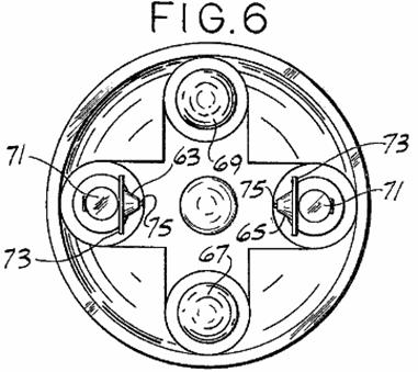
Fig.7 is an elevation of an electrode rod of an engine of this invention:
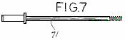
Fig.8 is an elevation, with parts broken away, of one type of electrode used in an engine of this invention:
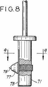
Fig.9 is a view taken generally
along line 9--9 of Fig.8:
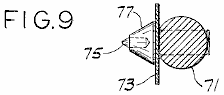
Fig.10 is a cross-sectional view of
a second type of electrode used in an engine of this invention:

Fig.11 is a cross-sectional view similar to Fig.5 showing the piston in its uppermost position:
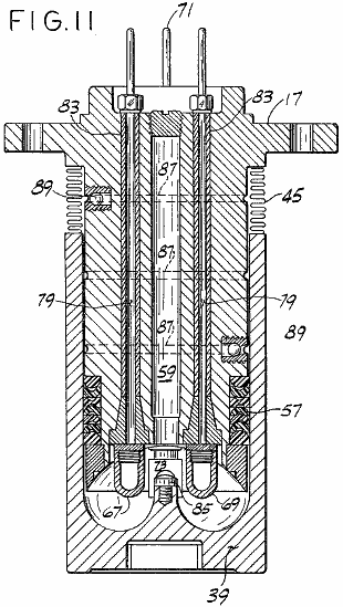
Fig.12 is a cross-sectional view similar to Fig.5 showing an alternative cylinder used in an engine of this invention:
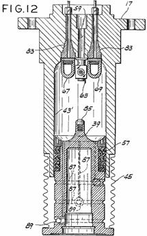
Fig.12A is a cross-sectional view
similar to Fig.5 and Fig.12, but on a reduced scale and with
parts broken away, showing an additional embodiment of a cylinder head used in
an engine of this invention:

Fig.13A and Fig.13B are schematic diagrams of the electrical circuitry for an engine of this invention:

Fig.14 is a schematic diagram of an
alternative high-voltage ignition system for an engine of this invention:
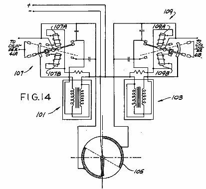
Fig.15 is a schematic diagram of an electronic switching unit for an engine of this invention:
Fig.16 is a schematic diagram of a regulator/electronic switching unit for an engine of this invention:
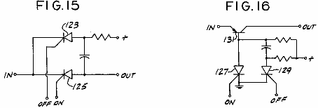
Figs.17A-17D are schematic diagrams of a fuel mixer of the present invention:
Fig.18 is a schematic diagram of the mixing chamber portion of the fuel mixer shown in Figs.17A-17D:
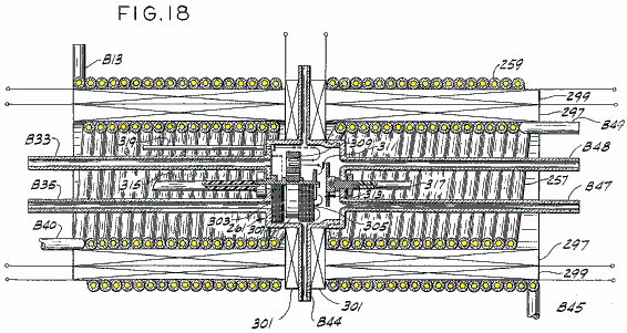
Figs.19A-19E are schematic diagrams of a portion of the electrical circuitry of the fuel mixer shown in Figs.17A-17D:
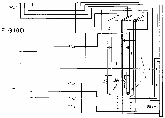
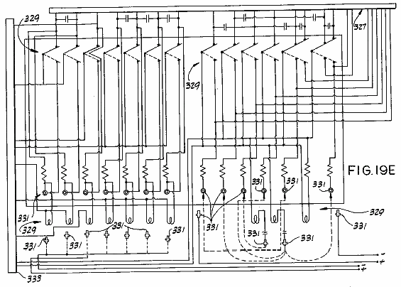
Figs.20A-20F are schematic diagrams of the rest of the electrical circuitry of the fuel mixer shown in Figs.17A-17D:
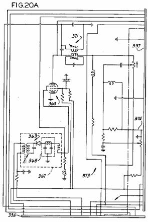
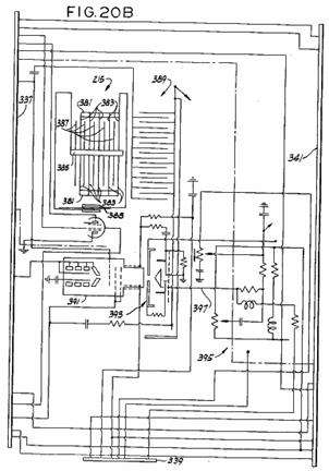
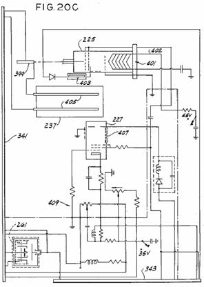
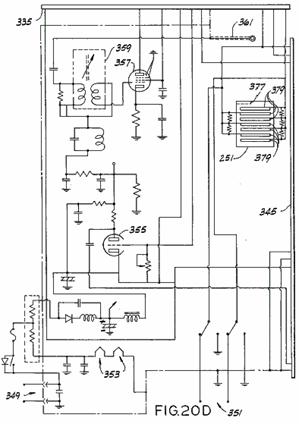
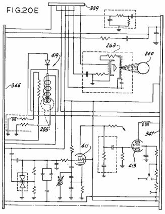
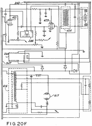
Note: Corresponding reference characters indicate corresponding parts throughout all of the views of the drawings.
DESCRIPTION OF A PREFERRED EMBODIMENT
Referring to the drawings, there is shown in Fig.1 a two-cylinder engine 11
comprising a block 13 preferably of
a nonmagnetic material such as aluminium, a nonmagnetic head 15, and a pair of cylinder heads 17A and 17B of a magnetisable material such as 0.1-0.3% carbon steel. Also shown in Fig.1 is a flywheel 19
attached to a crankshaft 21, a
generator 23, a high-voltage coil 25, a distributor 27 attached by a gear arrangement shown in part at 29 to the crankshaft, and an electrical
cable 31 which is connected to the
distributor and to both cylinders. Cable
31 (see Fig.2) is also electrically connected to a switching unit 33 which preferably comprises a
plurality of silicon controlled rectifiers (SCRs) or transistors. Also shown in Fig.2 is a second electrical connection of the cable to the
cylinders, which connection is indicated generally at 35. Turning to Fig.3, there is shown a starter motor 37 as well as a clearer view of the
connections 35 to each cylinder.
A cross section of the engine is shown in Fig.4. The cylinder heads have associated with them, pistons marked 39A and 39B, respectively, the heads and pistons define opposite ends of a pair of chambers or cylinders 41A and 41B respectively. The pistons are made of a magnetisable material. Although only two chambers are shown, the engine can include any number. It is preferred, however, for reasons set forth below, that there be an even number of cylinders. Pistons 39A and 39B move axially with respect to their corresponding heads from a first position (the position of piston 39A in Fig.4) to a second position (the position of piston 39B) and back, each piston being suitably connected to crankshaft 21. As shown in Fig.4, this suitable connection can include a connecting rod CR, a wrist pin WP, and a lower piston portion or power piston LP. The connecting rods and/or power pistons must be of non-magnetisable material. When a split piston is used, pistons 39A and 39B are suitably connected to lower piston portions LP by bolting, spring-loaded press fitting, or the like. Pistons 39A and 39B are attached 180 degrees apart from each other with respect to the crankshaft so that when one piston is at top dead centre (TDC) the other will be at bottom dead centre (BDC) and vice versa. Additional pairs of cylinders may be added as desired but the pistons of each pair should be attached to the crankshaft 180 degrees from each other. Of course, the relative position of each piston with respect to its respective head determines the volume of its chamber.
Integral with the piston bodies are walls 43 which form the walls of the chambers. Preferably, a set of air-tight bellows 45, of similar construction to that sold under the designation ME 197-0009-001 by the Belfab Company of Daytona Beach, Fla., are suitably secured between walls 43 and cylinder heads 17A and 17B respectively to form an airtight seal between each piston and its cylinder head. While walls 43 and piston 39 can be made of one magnetisable piece, a preferable and more efficient construction has walls 43 separate from piston 39 and made of a non-magnetisable material. The length of time that a given engine will run is a function of the efficacy of its sealing system. Means, such as bellows 45, for hermetically sealing the cylinders will optimise said length of time. Such a hermetic seal should be secured between walls 43 and cylinder heads 17 to form an airtight seal between them. This seal could be the airtight bellows system shown or some other sealing system such as an oil sealing system.
Cylinder bodies 47 (see Fig.4), made of nonmagnetic material
such as stainless steel, extend from the point of attachment of each bellows to
its cylinder head to the base of the corresponding pistons, forming sleeves for
each piston in which each piston moves.
Three sets of electric coils 49A,
49B, 51A, 51B, and 53A, 53B, are
wound around sleeves 47, and hence
around chambers 41A and 41B, respectively, for generating
magnetic fields in the chambers, those coils being generally coaxial with their
respective chambers. Each of these coils
has an inductance of approximately 100 mH. It is preferred that 14-19 gauge
wire be used to wind these coils and that the coils be coated with a suitable
coating, such as #9615 hardener from Furane Plastics, Inc., of Los Angeles,
California, or the coating sold by the Epoxylite Corp. of South El Monte,
California under the trade designation Epoxylite 8683. Each chamber is also surrounded by a pair of
capacitors, C1A, C1B and C2A, C2B wound around it, capacitors C1A, C1B having a
capacitance of approximately 1.3 microfarads and capacitors C2A, C2B having a capacitance of
approximately 2.2 microfarads. The coils
and capacitors are potted in hardened epoxy of fibreglass material 55.
The epoxy resin and hardener sold under the designations EPI Bond 121
and #9615 hardener by Furane Plastics, supra, are satisfactory, but other epoxy
material which will remain stable at temperatures up to 200 degrees F would
probably also be acceptable. It is preferred that a small amount of
graphite such as that sold under the trade designation Asbury 225 by Asbury
Graphite, Inc. of Rodeo, Calif., be included in the epoxy potting to prevent
nuclear particles formed in the chamber from escaping from the apparatus. Ten to 15% graphite to epoxy by weight is
more than enough.
A typical
cylinder is shown in section in Fig.5,
showing the piston in its fully extended position with respect to the head and
showing many details on a somewhat larger scale than that of Fig.4.
A set of seals 57, made of a
material such as that sold under the trade designation Teflon by the DuPont
Company of
The cylinder head has a generally concave depression therein, indicated at 61, which defines the top end of the
chamber. A plurality of electrodes for
exciting and igniting the working fluid extend through the cylinder head into
the chamber. Two of those electrodes,
shown in section in Fig.5 and
labelled 63 and 65, have tungsten points 75,
while the other two, labelled 67 and
69 (see Fig.6 for electrode 69)
are containers called, respectively, the anode and the cathode. The electrodes are generally equidistantly
spaced from the axes of their chambers and are generally coplanar to each
other, their mutual plane being perpendicular to the axes of their
chambers. Each electrode is positioned
90 degrees from adjacent electrodes in this embodiment and are generally
positioned so that a line from the anode to the cathode and a line between the
other two electrodes intersect at a focal point generally on the axis of the
chamber. The radial distance of each
electrode from the focal point is fixed for a reason discussed below. The general construction of electrodes 63 and 65 is shown in Fig.6 to Fig.9.
These electrodes include a conductive rod 71 (see Fig.7)
preferably of brass or copper; a conductive, generally rectangular plate 73 (see Fig.6, Fig.8 and Fig.9); and tungsten point 75 mounted in a conductive base 77 generally at right angles to the
plate (see Fig.8 and Fig.9).
The construction of the anode and cathode is shown in Fig.10. Each includes a conductive rod 79 and a container 81. The cathode container is substantially pure
aluminium. If desired, aluminium alloys
with, e.g., less than 5% copper, 1% manganese and 2% magnesium may be
used. In one embodiment, the cathode
container contains approximately four grams of thorium-232 and is filled with
argon. In this same embodiment the anode container is copper or brass and
contains approximately two grams of rubidium-37 and approximately three grams
of phosphorus-15 hermetically sealed in mineral oil. In a second embodiment,
the cathode is still aluminium, but it contains at least two grams of
rubidium-37 in addition to the approximately four grams of thorium-232 in
either argon or mineral oil. In this
second embodiment, the anode is also aluminium and contains at least 4 grams of
phosphorus-15 and at least 2 grams of thorium-232 in argon or mineral oil. Alternatively, mesothorium may be used for
the thorium, strontium-38 may be used for the rubidium, and sulphur-16 may be
used for the phosphorus. Rods 71 and 79 extend through cylinder head 17 to the exterior where electrical connections are made to the
electrodes. Each rod is surrounded by
one of four insulating sleeves 83,
the lower portion of each of which being flared outwards to seat firmly in the
cylinder head.
The piston has a generally semi-toroidal depression in its upper surface (see Fig.4, Fig.5 and Fig.11) and carries a conductive discharge point 85 of copper, brass or bronze generally along the axis of the chamber. When the piston is generally extended, the discharge point is a substantial distance from the electrodes. But when the piston is in its upper position (see Fig.11), the discharge point is positioned generally between all four electrodes and close to them, there being gaps between the electrodes and the discharge point. When the piston is in this upper position, the electrodes extend somewhat into the semi-toroidal depression in the piston's upper surface and the chamber is generally toroidal in shape. The volume of the chamber shown in Fig.11 can be from approximately 6.0 cubic inches (100 cc) or larger. Given the present state of the art, 1500 cubic inches (25,000 cc) appears to be the upper limit. A plurality of ports 87 and one-way valves 89 return working fluid which escapes from the chamber back into it, so long as a sealing system such as bellows 45 is used.
An alternative cylinder head/piston arrangement is shown in Fig.12.
The main difference between this arrangement and that of Fig.5 is that the chamber walls, here
labelled 43' are integrally formed
with the head. As a result seals 57 are carried by the piston rather
than by the head, the attachment of bellows 45 is somewhat different, and the fluid-returning valves and ports
are part of the piston rather than of the head. Otherwise these arrangements
are substantially the same. Preferably,
the cylinders of both arrangements are hermetically sealed.
An additional embodiment of a cylinder head/piston arrangement used in the present invention is shown in Fig.12A. In this arrangement, a tapered sleeve 17C mates between cylinder head 17 and piston 39, a plurality of seals 57 are provided, and electrodes 67 and 69 have a somewhat different shape. Also, in this embodiment, a chamber 90 is provided in cylinder head 17 for storing additional working fluid, i.e., the purpose of chamber 90 is to extend the operating time between refuelling by circulating the working fluid, viz. the mixture of inert gases described, between cylinder 41 and chamber 90 as needed so that the reactions in cylinder 41 are not adversely affected. To accomplish this, this embodiment further includes a two-way circulation valve 90B, a relief valve 90C, and duct or passageway 90D for evacuating and filling chamber 90, a duct or passageway 90E for evacuating and filling cylinder 41, a passageway 90F between chamber 90 and cylinder 41 in which two-way valve 90B is disposed, a sensor 90G and a plurality of small pressure relief holes 90H. Relief holes 90H serve to relieve the pressure on bellows 45 as the piston moves from BDC to TDC.
In larger engines holes 90H should be replaced with one way valves. Two-way valve 90B is either controlled by sensor 90G or is manually operated, as desired, to allow the circulation of gases between chamber 90 and cylinder 41. The sensor itself detects a condition requiring the opening or closing of valve 90B and signals that condition to the valve. For example, sensor 90G can measure pressure in cylinder 41 while the piston is at top dead centre. A predetermined cylinder pressure can cause a spring to compress, causing the valve to open or close as appropriate. A subsequent change in the cylinder pressure would then cause another change in the valve. Another sensor (not shown) could measure the physical location of the piston by a physical trip switch or an electric eye, or it could measure angular distance from top dead centre on the distributor or the crankshaft. The sensor must keep the gas pressure in chamber 90 at one atmosphere, plus or minus 5%, and at top dead centre, cylinder 41 should also be at that pressure. If gas is lost from the system, it is more important to maintain the proper pressure in cylinder 41. Alternatively, a small passage between cylinder 41 and chamber 90 could function in a passive manner to satisfactorily accomplish the same result. From the above, it can be seen that this embodiment utilises the hollowed out centre of the cylinder head for storing additional working fluid, which fluid is circulated between chamber 90 and cylinder 41 through a valve system comprising valve 90B and sensor 90G with the moving piston causing the gases to circulate.
The electrical circuitry for engine 11
includes (see Fig.13A) a 24 V
battery B1, an ignition switch SW1, a starter switch SW2, starter motor 37, a main circuit switch SW4,
a step-down transformer 93 (e.g., a
24 V to 3.5 V transformer), a switch SW6
for supplying power to ignition coil 25
(shown in Fig.13A and Fig.13B as two separate ignition coils 25A and 25B), and various decoupling diodes.
The circuitry of Fig.13A also
includes a high frequency voltage source or oscillator 95 for supplying rapidly varying voltage through two electronic
current regulators 97A, 97B (see Fig.13B for regulator 97B) to the anode and cathode
electrodes of each cylinder, and a high-voltage distributor 99 for distributing 40,000 volt pulses
to the cylinders. Distributor 99 has two wipers 99A and 99B and supplies
three pulses to each cylinder per cycle.
Wipers 99A and 99B are 180 degrees out of phase with
each other and each operates to supply pulses to its respective cylinder from
TDC to 120 degrees thereafter. More
pulses are desirable and therefore a better distributor arrangement (shown in Fig.14) may be used. The arrangement shown in Fig.14 includes two ignition coils 101, 103, a simple
distributor 105 and a pair of
magnetic ignition circuits 107 and 109, described below. Of course many other ignition systems could also
be developed. For example, a single
circuit might be used in place of circuits 107,
109, additional induction coils
might be added to the ignition coils to assist in starting or a resistor could
be added to the ignition coils to ensure a constant 40,000 volt output
regardless of engine rpm. Also, a
solid-state distributor could be used instead of the mechanical distributor
labelled 99.
Referring back to Fig.13A, for
engines of more than 1000 hp a high frequency source 95 could be used to control engine RPM. The output frequency is controlled by a foot
pedal similar to an accelerator pedal in a conventional vehicle. The output frequency varies through a range
of from approximately 2.057 MHz to approximately 27.120 MHz with an output
current of approximately 8.4 amps. The
speed of engine 11 is controlled by
the output frequency of source 95. The high frequency current, as described
below, is directed to each cylinder in turn by circuitry described below. For engines producing from 300 to 1000 hp (not
shown), a high frequency source having a constant output of 27.120 MHz with a
constant current of 3.4 amps which is continually supplied to all cylinders
could be used. In this case an
autotransformer, such as that sold under the trade designation Variac by the
General Radio Company, controlled by a foot pedal varies the voltage to each
cylinder from 5 to 24 volts DC at 4.5 amps, using power from the batteries or
the alternator. The DC current from the
Variac is switched from cylinder to cylinder by two small electronic switching
units which in turn are controlled by larger electronic switching units. For the smallest engines (not shown), a high
frequency generator could supply a constant output of 27.120 MHz with a
constant current of 4.2 amps to the cylinders during starting only. Speed control would be achieved by a Variac
as described above which controls the DC voltage supplied to the cylinders in
turn within a range of from 5 to 24 volts at a current of 5.2 amps. In this case, once the engine is running, the
full voltage needed to ignite the (smaller) quantity of gases is obtained from
the electrodes in the other cylinder of the pair.
The circuitry of Fig.13A also
includes the generator, a voltage regulator and relay 111, five electronic switching units 113, 115, 117, 119 and 121,
electrodes 63 and 65 associated with chamber 41A (hereinafter chamber 41A is sometimes referred to as the
"A" cylinder and chamber 41B is sometimes referred to as the
"B" cylinder), anode 67, cathode 69, magnetic coils 49A, 51A
and 53A, capacitors C1A and C2A, and various decoupling diodes. The electronic switching units
can take a variety of forms. For
example, one simple form (see Fig.15)
includes a pair of SCRs 123 and 125.
The switching unit is connected at terminal IN to the corresponding line
on the input side and at terminal OUT to the corresponding line on the output
side. When a voltage of 3.5 volts is supplied from the battery through a
distributor, for example, to the ON terminal, SCR 125 conducts, thereby completing a circuit through the switching
unit. Conversely, when 3.5 volts is
applied to the OFF terminal, SCR 123
conducts and the circuit is broken.
Likewise, the circuit for regulators 97A and 97B (see Fig.16) includes two SCRs 127 and 129 and a PNP transistor 131. In this circuit when SCR 127 is gated on, it forces transistor 131 into conduction, thereby completing the circuit through the
regulator. When SCR 129 is gated on, the circuit through transistor 131 is broken. A number of other configurations may be used
in place of those of Fig.15 and Fig.16 and not all would use SCRs. For example, one triode could be used to
replace two main SCRs, or transistors could be used instead of SCRs.
A pair of low-voltage distributors 135
and 137 are also shown in Fig.13A. Distributors 135 and 137 provide
gating pulses for the electronic switching units of Fig.13A and Fig.13B. Of course, solid-state distributors could
also replace mechanical distributors 135
and 137.
In addition, the engine circuitry includes (see Fig.13B) five electronic switching units 143, 145, 147, 149 and 151
corresponding to units 113, 115, 117,
119 and 121 of Fig.13A, electrodes 63 and 65 of the "B"
cylinder, anode 67, cathode 69, electric coils 49B, 51B and 53B,
capacitors C1B and C2B, and various decoupling
diodes. The circuitry of Fig.13B is generally the same as the
corresponding portions of Fig.13A,
so the description of one for the most part applies to both. Of course, if more than two cylinders are
used, each pair of cylinders would have associated with them, circuitry such as
that shown in Fig.13A and Fig.13B. The circuitry of Fig.13A is connected to that of Fig.13B by the lines L1-L17.
The working fluid and the fuel for the engine are one and the same and consist
of a mixture of inert gases, which mixture consists essentially of helium,
neon, argon, krypton and xenon. It is
preferred that the mixture contain 35.6% helium, 26.3% neon, 16.9% argon, 12.7%
krypton, and 8.5% xenon by volume, it having been calculated that this particular
mixture gives the maximum operation time without refuelling. Generally, the
initial mixture may contain, by volume, approximately 36% helium, approximately
26% neon, approximately 17% argon, approximately 13% krypton, and approximately
8% xenon. This mixture results from a calculation that equalises the total
charge for each of the gases used after compensating for the fact that one
inert gas, viz. radon, is not used. The
foregoing is confirmed by a spectroscopic flashing, described below, that occurs
during the mixing process. If one of
the gases in the mixture has less than the prescribed percentage, it will
become over-excited. Similarly, if one
of the gases has more than the prescribed percentage, that gas will be
under-excited. These percentages do not
vary with the size of the cylinder.
Operation of the engine is as follows: At room temperature, each cylinder is
filled with a one atmosphere charge of the fuel mixture of approximately 6
cubic inches (100 cc) /cylinder (in the case of the smallest engine) by means
of filler tube 59. The filler tubes are then plugged and the
cylinders are installed in the engine as shown in Fig.4, one piston being in the fully extended position and the
other being in the fully retracted position.
To start the engine, the ignition and starter switches are closed, as is
switch SW6. This causes the starter motor to crank the
engine, which in turn causes the wiper arms of the distributors to rotate. The
starting process begins, for example, when the pistons are in the positions
shown in Fig.4. Ignition coil 25 and distributor 99 (see Fig.13A)
generate a 40,000 volt pulse which is supplied to electrode 65 of chamber 41A. Therefore, a momentary
high potential exists between electrodes 63
and 65 and the plates on each. The discharge point on piston 39A is adjacent these electrodes at
this time and sparks occur between one or more of the electrodes and the
discharge point to partially excite, e.g. ionise, the gaseous fuel mixture.
The gaseous fuel mixture in cylinder 41A
is further excited by magnetic fields set up in the chamber by coil 49A.
This coil is connected to the output side of electronic switching unit 121 and, through switching unit 113, to the battery and the
generator. At this time, i.e., between
approximately 5 degrees before TDC and TDC, distributor 135 is supplying a gating signal to unit 121. Any current present on
the input side of unit 121,
therefore, passes through unit 121
to energise coil 49A. Moreover, high frequency current from
oscillator 95 is supplied via
regulator 97A to coil 49A.
This current passes through regulator and relay 97A because the gating signal supplied from distributor 135 to unit 121 is also supplied to relay 97A. The current from switching unit 121 and from oscillator 95 also is supplied to the anode and
the cathode. It is calculated that this
causes radioactive rays (x-rays) to flow between the anode and the cathode,
thereby further exciting the gaseous mixture.
As the starter motor continues cranking, piston 39A begins moving downward, piston 39B begins moving upward, and the wiper arms of the distributors
rotate. (Needless to say, a solid-state
distributor would not rotate. The distributor could utilise photo cells, either
light or reflected light, rather than contact points). After 45 degrees of rotation, distributor 135 supplies a gating pulse to
electronic switching unit 119,
thereby completing a circuit through unit 119.
The input to unit 119 is connected
to the same lines that supply current to coil 49A. The completion of the circuit through unit 119, therefore, causes coil 51A to be energised in the same manner
as coil 49A. After an additional 45 degrees of rotation,
distributor 135 gates on electronic
switching unit 117 which completes a
circuit to the same lines. The output terminal of unit 117 is connected to coil 53A,
and so this coil is energised when unit 117
is gated on. All three coils of the
"A" cylinder remain
energised and, therefore, generating magnetic fields in chamber 41A until piston 39A reaches BDC.
As piston 39A moves from TDC to BDC,
two additional 40,000 volt pulses (for a total of three) are supplied from
distributor 99 to the "A" cylinder. These pulses are spaced approximately 60
degrees apart. If more pulses are desired, the apparatus shown in Fig.14 may be used. In that case, the solenoids indicated
generally at 107A, 107B and 109A, 109B are energised to create a
number of rapid, high-voltage pulses which are supplied as indicated in Fig.14 to the cylinders, distributor 105 operating to supply pulses to only
one of the pair of cylinders at a time.
As piston 39A reaches BDC,
distributor 135 sends a pulse to the
OFF terminals of electronic switching units 121, 117 and 119,
respectively, causing all three coils 49A,
51A and 53A to be de-energised. At about the same time, i.e., between
approximately 5 degrees before TDC and TDC for piston 39B, distributor 137
supplies a gating pulse to the ON terminals of electronic switching units 113 and 115. The power inputs to units 113
and 115 come from the generator
through regulator 111 and from the
battery, and the outputs are directly connected to coils 49A and 53A. Therefore, when units 113 and 115 are gated
on, coils 49A and 53A are reenergised. But in this part of the cycle, the coils are
energised with the opposite polarity, causing a reversal in the magnetic field
in chamber 41A. Note that coil 51A is not energised at all during this portion of the cycle. Capacitors C1A and C2A are also
charged during the BDC to TDC portion of the cycle. (During the TDC to BDC
portion of the cycle, these capacitors are charged and/or discharged by the
same currents as are supplied to the anode and cathode since they are directly
connected to them).
As piston 39A moves upwards,
electrodes 63 and 65 serve as pick-up points in order to
conduct some of the current out of chamber 41A,
this current being generated by the excited gases in the chamber. This current is transferred via line L7 to electronic switching unit 151.
The same gating pulse which gated on units 113 and 115 was also
supplied from distributor 137 via
line L12 to gate on switching unit 151, so the current from the electrodes
of chamber 41A passes through unit 151 to the anode, cathode and
capacitors of chamber 41B, as well
as through switching units 147 and 149 to coils 49B, 51B and 53B. Thus it can be seen that electricity
generated in one cylinder during a portion of the cycle is transferred to the
other cylinder to assist in the excitation of the gaseous mixture in the
latter. Note that this electricity is
regulated to maintain a constant in-engine current. It should be noted, that twenty four volts
from the generator is always present on electrodes 63 and 65 during
operation to provide for pre-excitement of the gases.
From the above it can be seen that distributors 135 and 137 in
conjunction with electronic switching units 113, 115, 117, 119, 121, 143, 145, 147, 149 and 151 constitute the means for
individually energising coils 49A, 49B, 51A, 51B, 53A and 53B.
More particularly, they constitute the means to energise all the coils
of a given cylinder from the other cylinder when the first cylinder's piston is
moving from TDC to BDC and operate to energise only two (i.e., less than all)
of the coils from the alternator when that piston is moving from BDC to
TDC. Additionally, these components
constitute the means for energising the coils with a given polarity when the
piston of that cylinder is moving from TDC to BDC and for energising the first
and third coils with the opposite polarity when that piston is moving from BDC
to TDC.
As can also be seen, switching units 121
and 151 together with distributors 135 and 137 constitute the means for closing a circuit for flow of current
from chamber 41A to chamber 41B during the BDC to TDC portion of
the cycle of chamber 41A and for
closing a circuit for flow of current from chamber 41B to chamber 41A
during the TDC to BDC portion of the cycle of chamber 41A. Oscillator 95 constitutes the means for supplying
a time varying electrical voltage to the electrodes of each cylinder, and
oscillator 95, distributors 135 and 137, and regulators 97A
and 97B together constitute the
means for supplying the time varying voltage during a predetermined portion of
the cycle of each piston. Moreover,
distributor 99 together with
ignition coils 25A and 25B constitute the means for supplying
high-voltage pulses to the cylinders at predetermined times during the cycle of
each piston.
The cycle of piston 39B is exactly
the same as that of piston 39A
except for the 180 degree phase difference.
For each cylinder, it is calculated that the excitation as described
above causes the gases to separate into layers, the lowest atomic weight gas in
the mixture, namely helium, being disposed generally in the centre of each chamber,
neon forming the next layer, and so on until we reach xenon which is in
physical contact with the chamber walls.
The input current (power) to do this is the calculated potential of the
gas mixture. Since helium is located in
the centre of the chamber, the focal point of the electrode discharges and the
discharges between the anode and cathode is in the helium layer when the piston
is near TDC. As the piston moves
slightly below TDC, the electrons from electrodes 63 and 65 will no longer
strike the tip of the piston, but rather will intersect in the centre of the
cylinder (this is called "focal point electron and particle
collision") as will the alpha, beta and gamma rays from the anode and
cathode. Of course, the helium is in
this exact spot and is heavily ionised at that time. Thus the electrodes together with the source
of electrical power connected thereto constitute the means for ionising the
inert gas.
It is calculated that as a result of all the aforementioned interactions, an ignition discharge occurs in which the helium splits into hydrogen in a volume not larger than 2 or 3 x 10⁻⁶ cubic millimetres at a temperature of approximately 100,000,000 degrees F. Of course this temperature is confined to a very small space and the layering of the gases insulates the cylinder walls from it. Such heat excites the adjacent helium so that a plasma occurs. Consequently, there is a minute fusion reaction in the helium consisting of the energy conversion of a single helium atom, which releases sufficient energy to drive the piston in that chamber toward BDC with a force similar in magnitude to that generated in a cylinder of a conventional internal combustion engine. Electrodes 63 and 65 extend into the argon layer while each piston is in its BDC to TDC stroke so as to pick up some of the current flowing in that layer. It may take a cycle or two for the gases in the cylinders to become sufficiently excited for ignition to occur.
Once ignition does occur, the electrical operation of the engine continues as
before, without the operation of the starter motor. Distributor 99 supplies three pulses per cycle (or more if the magnetic
ignition system of Fig.14 is used)
to each cylinder; and distributors 135
and 137 continue to supply
"on" and "off" gating pulses to the electronic switching
units. The rpm of the engine is, as
explained above, governed by the frequency of the current from oscillator 95 (or in the case of smaller
horsepower units, by the DC voltage supplied to the cylinders from the Variac).
Because of the minute amount of fuel consumed in each cycle, it is calculated
that a cylinder can run at 1200 rpm approximately 1000 hours, if not more, on a
single charge of gas. Note that even at
1200 rpm, there will be intense heat occurring only 0.002% of the time. This means that input power need be applied
only sporadically. This power can be
supplied to a cylinder from the other cylinder of its pair by means of electronic
switching units which, in the case of SCRs, are themselves triggered by low
voltage (e.g. 3.5 V) current. Thus,
since electrical power generated in one cylinder is used to excite the gases in
the other cylinder of a pair, it is practical that the cylinders be paired as
discussed above. Capacitors are, of course,
used to store such energy for use during the proper portion of the cycle of
each cylinder.
From the above, it should be appreciated that the engine of this invention has
several advantages over presently proposed fusion reactors, such as smaller
size, lower energy requirements, etc.
But what are the bases of these advantages? For one, presently proposed fusion reactors
use hydrogen and its isotopes as a fuel instead of inert gases. Presumably this is because hydrogen requires
less excitement power. While this is true,
the input power that is required in order to make hydrogen reactors operate
makes the excitation power almost insignificant. For example, to keep a hydrogen reactor from
short circuiting, the hydrogen gas has to be separated from the reactor walls
while it is in the plasma state. This separation is accomplished by the
maintenance of a near vacuum in the reactor and by the concentration of the gas
in the centre of the reactor (typically a toroid) by a continuous, intense
magnetic field. Accordingly, separation
requires a large amount of input energy.
In the present invention, on the other hand, the greater excitation energy of
the fuel is more than compensated for by the fact that the input energy for
operation can be minimised by manipulation of the unique characteristics of the
inert gases. First, helium is the inert
gas used for fusion in the present invention. The helium is primarily isolated
from the walls of the container by the layering of the other inert gases, which
layering is caused by the different excitation potential (because of the
different atomic weights) of the different inert gases, said excitation being
caused by the action of the electrodes, anode and cathode in a magnetic
field. This excitation causes the gases
each to be excited in inverse proportion to their atomic numbers, the lighter
gases being excited correspondingly more.
Helium, therefore, forms the central core with the other four gases
forming layers, in order, around the helium.
The helium is secondarily isolated from the walls of the container by a
modest vacuum (in comparison to the vacuum in hydrogen reactors) which is
caused partially by the "choking" effect of the coils and partially
by the enlargement of the combustion chamber as the piston moves from TDC to
BDC. (Unexcited, the gases are at one
atmosphere at TDC). Second, argon, the
middle gas of the five, is a good electrical conductor and becomes an excellent
conductor when (as explained below) it is polarised during the mixing
process. By placing the electrodes such
that they are in the argon layer, electrical energy can be tapped from one
cylinder for use in the other. During a
piston's movement from BDC to TDC, the gases are caused to circulate in the
cylinder by the change in the polarity of the coils, which occurs at BDC.
During such circulation, the gases remain layered, causing the argon atoms to be relatively close to each other, thereby optimising the conductivity of the argon. This conductivity optimisation is further enhanced by a mild choking effect that is due to the magnetic fields. The circulation of the highly conductive argon results in a continuous cutting of the magnetic lines of force so that the current flows through the electrodes. This production of electricity is similar to the rotating copper wire cutting the magnetic lines of force in a conventional generator except that the rotating copper wire is replaced by the rotating, highly conductive argon. The amount of electricity that can be produced in this manner is a function of how many magnetic field lines are available to be cut. If one of the coils, or all three of the coils or two adjacent coils were energised, there would be only one field with electricity produced at each end. By energising the top and the bottom coil, two separate fields are produced, with electricity produced at four points.
A five coil
system, if there were sufficient space, would produce three fields with the
top, bottom and middle coils energised.
Six points for electricity production would result. The number of coils that can be installed on
a given cylinder is a function of space limitations. The recombination of gas atoms during the BDC
to TDC phase causes the radiation of electrical energy which also provides a
minor portion of the electricity that the electrode picks up. Additional non-grounded electrodes in each
cylinder would result in more electricity being tapped off. It should be noted that during the BDC to TDC
phase, the anode and the cathode are also in the argon layer and, like the
electrodes, they pick up electricity, which charges the capacitors around the
cylinder. Third, inert gases remain a
mixture and do not combine because of the completeness of the electron shells.
They are therefore well suited to a cycle whereby they are continually
organised and reorganised. Fourth, as
the helium atoms are consumed, the other gases have the capacity to absorb the
charge of the consumed gas so that the total charge of the mixture remains the
same.
The second basis of these advantages of the present engine over proposed fusion
reactors concerns the fact that hydrogen reactors develop heat which generates
steam to turn turbines in order to generate electrical power. This requires
tremendous input energy on a continuous basis. The present invention operates
on a closed cycle, utilising pistons and a crankshaft which does not require a
continuous plasma but rather an infrequent, short duration (10-6 second)
plasma that therefore requires much less input energy. In the present
invention, a plasma lasting longer than 10-6 second is not necessary because
sufficient pressure is generated in that time to turn the engine. A plasma of longer duration could damage the
engine if the heat were sufficiently intense to be transmitted through the
inert gas layers to the cylinder walls.
A similar heat build-up in the engine can occur if the repetition rate
is increased. Such an increase can be
used to increase the horsepower per engine size but at the cost of adding a
cooling system, using more expensive engine components, and increasing fuel
consumption. Note that even though
layers of inert gases insulate the cylinder walls, there might be some slight
increase in the temperature of the gas layers after a number of cycles, i.e.,
after a number of ignitions.
Whereas hydrogen fusion reactors cannot directly produce power by driving a
piston (because of the required vacuum), the present invention uses the layered
inert gases to transmit the power from the plasma to each gas in turn until the
power is applied to a piston, which can easily be translated into rotary
motion. The layered gases also cushion the piston from the full force of the
ignition. Moreover, the fields inside
the cylinder undergoing expansion cause the gases to shrink, thereby taking up
some of the pressure generated by the explosion and preventing rupturing of the
cylinder walls.
Turning now to Fig.17A to Fig.17D, there is shown apparatus 201 for preparing the fuel mixture for
engine 11. For convenience apparatus 201 is called a mixer although it
should be understood that the apparatus not only mixes the gases which form the
fuel but also performs many other vital functions as well. The five constituent inert gases are
introduced in precise, predetermined proportions. The mixer extracts, filters and neutralises
the non-inert gases and other contaminants which may be found in the gas
mixture. It also increases the potential capacity of gas atoms, discharges the
krypton and xenon gases, polarises the argon gases, ionises the gases in a
manner such that the ionisation is maintained until the gas has been utilised
and otherwise prepares them for use as a fuel in engine 11. In particular, the mixer
makes the gases easier to excite during operation of the engine. Mixing does not mean an atomic or molecular
combination or unification of gases because inert gases cannot chemically
combine, in general, due to the completeness of the outer shell of
electrons. During mixing, the various
gases form a homogeneous mixture. The
mixing of the five inert gases in apparatus 201 is somewhat analogous to preparing a five part liquid chemical
mixture by titration. In such a mixture,
the proportions of the different chemicals are accurately determined by
visually observing the end point of each reaction during titration. In apparatus 201, a visible, spectroscopic flash of light accompanies the
desired end point of the introduction of each new gas as it reaches its proper,
precalculated proportion. (Each gas has
its own distinctive, characteristic, spectroscopic display). The ends points are theoretically calculated
and are determined by pre-set voltages on each of a group of ionising heads in
the apparatus, as described below.
Mixer 201 includes (see Fig.17A) an intake port, indicated
generally at 203, which during
operation is connected to a source 205
of helium gas, a gauge 206, glass
tubing 207 comprising a plurality of
branches B10-B25 for flow of the
gases through the mixer, a plurality of valves V1-V11 in the branches, which valves may be opened or closed as
necessary, three gas reservoirs 209, 211
and 213 for storing small quantities
of helium, argon and neon gas respectively, an ionising and filtering unit 215 for filtering undesired non-inert
gases and contaminants out of the fuel mixture, for regulating the gas atom
electron charge and to absorb the free flowing electrons, a gas flow
circulation pump 217, two ionising
heads 219 and 221, and three quality control and exhaust valves V12-V14. The mixer also comprises (see Fig.17B) a high frequency discharge
tube 225, a non-directed cathode ray
tube 227, two more ionising heads 229 and 231, two additional gas reservoirs 233 and 235 for storing
small quantities of xenon and krypton, a quadruple magnetic coil 237, a group of valves V15-V24, valves V23 and V24 being
quality control and exhaust valves, and a plurality of additional glass tubing
branches B26-B32.
Turning to Fig.17C, mixer 201 also includes additional ionising
heads 239, 240 and 241, additional valves V25-V46, V39A and V40A, valves V29 and V32 being quality control and exhaust valves and valve V39A being a check valve, a vacuum and
pressure gauge 242 between valves V35 and V36, tubing branches B34-B49
(branch B39 consisting of two parts B39A and B39B), a pair of intake ports 243
and 245 which during operation are
connected to sources 247 and 249 of argon and neon gas respectively,
gauges 250A and 250B, a spark chamber 251,
a hydrogen and oxygen retention chamber 253
containing No. 650 steel dust in a silk filter, an ion gauge 255 (which can be an RG 75K type Ion
Gauge from Glass Instruments, Inc. of Pasadena, Calif.) for removing excess
inert gases from the mixture, inner and outer coils of glass tubing 257 and 259 surrounding a mixing chamber 261, a focused x-ray tube 263
for subjecting the mixture flowing through it to 15-20 millirem alpha radiation
and 120-125 millirem beta radiation, a directed cathode ray tube 265, two twin parallel magnetic coils 266 and 267, and a focusing magnetic coil 269. It is important that
coils 266 and 267 be immediately adjacent mixing chamber 261. And (see Fig.17D) the mixer also comprises three
more ionising heads 271, 273 and 275, two entry ports 277
and 279 which during operation are
connected to sources 281 and 283 of krypton and xenon respectively,
gauges 284A and 284B, a high frequency discharge tube 285, a twin parallel magnetic coil 287 surrounding a polariser 289
for polarising the argon, said polarise containing fine steel particles which
are polarised by coils 287 and which
in turn polarise argon, a second hydrogen retention chamber 291, a pair of tubing branches B50 and B51, two filters 293 and
295 and a plurality of valves V47-V59, valves V57 and V59 being
quality control and exhaust valves.
Inner and outer glass tubing coils 257
and 259 and mixing chamber 261 are shown in cross section in Fig.18.
Intermediate glass coils 257
and 259 are two magnetic coils 297 and 299 having an inductance of approximately 130 mH. A yoke coil 301 is positioned in a semi-circle around mixing chamber 261.
Inside mixing chamber 261 are
located a pair of screens 303 and 305, insulators 307 and 309, and a pair
of spark gaps indicated generally at 311
and 313. A high frequency amplitude modulated source
provides 120 V AC, 60 Hz, 8.4 amp, 560 watt, 27,120 to 40,000 MHz plus or minus
160 KHz current via heavily insulated wires 315 and 317 to the
chamber. These wires are about twelve
gauge, like those used as spark plug wires on internal combustion engines. Additionally 95 volt Direct Current is
supplied via a smaller (e.g. sixteen to eighteen gauge) insulated wire 319.
As described below, the gases to be mixed and prepared flow through
chamber 261 and are suitably treated
therein by the action of the various fields present in the chamber.
The magnetic coils, ionisation heads, and pump 217, along with the required electrical interconnections, are
schematically shown in Fig.19A to Fig.19E. More particularly, heads 239 and 241 are shown in
Fig.19A, as is pump 217.
Each ionising head has two electrodes with a gap between them to cause
ionisation of gases flowing through the head, the electrodes being connected to
a source of electrical power. Pump 217
is directly connected to a source of power (either AC or DC as required by the
particular pump being used). The connections between the circuitry on Fig.19A and that on Fig.19B are shown as a plug 321, it being understood that this plug
represents a suitable one-to-one connection between the lines of Fig.19A and those of Fig.19B.
The remaining ionising heads and all the magnetic coils are shown in Fig.19B. For clarity, the coils are shown in an
unconventional form. Quadruple coil 237 (shown at the top of Fig.19B) has one side of each winding
connected in common but the other sides are connected to different lines. Coil 223
consists of two windings in parallel.
Coils 297 and 299, the ones around the mixing
chamber, are shown overlapping, it being understood that coil 297 is actually interior of coil 299.
Yoke coil 301, as shown,
extends half-way from the bottom to the top of coils 297 and 299. Twin parallel magnetic coils 267 are connected in parallel with each
other, both sides of focusing coil 269
being connected to one node of coils 267. Likewise coils 287 are connected in parallel.
The connections between the lines of Fig.19B and those of Fig.19C
and Fig.19D are shown as plugs 323 and 325, although other suitable one-to-one connections could certainly
be made. Fig.19C shows the interconnecting lines between Fig.19B and Fig.19E. A plug 327 or other suitable one-to-one
connections connects the lines of Fig.19C
and Fig.19E.
A plurality of power sources, like the above-mentioned Variacs, of suitable
voltages and currents as well as a plurality of relays 329, and plugs 331 are
shown on Fig.19D and Fig.19E. The connections between these two Figures is
shown as a plug 333. It should be appreciated that the Variacs can
be adjusted by the operator as necessary to supply the desired voltages to the
aforementioned coils and ionising heads. It should also be realised that the desired
relays can be closed or opened as needed by connecting or disconnecting the two
parts of the corresponding plug 331. That is, by use of plugs 331, the operator can control the energising of the ionising heads
and magnetic coils as desired. Plugs 331 are also an aid in checking to
ensure that each component is in operating condition just prior to its
use. Of course, the manipulation of the
power sources and the relays need not be performed manually; it could be
automated.
The remaining circuitry for the mixer is shown on Fig.20A to Fig.20F. For convenience, plugs 335, 337, 339, 341, 343, 345 and 347 are shown as connecting the
circuitry shown in the various Figures, although other suitable one-to-one
connections may be used. The chassis of
the apparatus is shown on these Figures in phantom and is grounded. The power supply for the apparatus is shown
in part on Fig.20A and Fig.20D and includes an input 349 (see Fig.20D) which is connected to 120 volt, 60 Hz power during
operation and an input 351 which is
connected to the aforementioned high frequency generator or some other suitable
source of approximately 27,120 MHz current.
The power supply includes a pair of tuners 353, numerous RLC circuits, a triode 355, a pentode 357 with
a ZnS screen, a variable transformer 359,
an input control 361, a second
variable transformer 363 (see Fig.20A) which together with a filter 365 forms a 2.0 volts (peak-to-peak)
power supply 367, a pentode 369, a variable transformer 371, and a resistor network indicated
generally at 373. Exemplary voltages in the power supply
during operation are as follows: The anode of triode 355 is at 145 V, the control grid at 135 V and the cathode at -25
V. The voltage at the top of the
right-hand winding of transformer 359
is -5 V. The anode of pentode 357 is at 143 V, the top grid is
grounded (as is the ZnS screen), the bottom grid is connected to transformer 359, and the control electrode is at
143 V. The input to supply 367 is 143 volts AC while its output,
as stated above, is 2 V (peak-to-peak).
The anode of pentode 369 is
at 60 V, the grids at -1.5 V, the control electrode at 130 V, and the cathode
is substantially at ground. The output
of resistor network 373, labelled 375, is at 45 V.
Also shown on Fig.20D is spark chamber
251.
Spark chamber 251 includes a
small amount of thorium, indicated at 377,
and a plurality of parallel brass plates 379. When the gases in the mixer reach the proper
ionisation, the alpha particles emitted by the thorium shown up as flashes of light
in the spark chamber.
Turning now to Fig.20B, ionising and
filtering unit 215 includes a pair
of conductive supports 381 for a
plurality of conductors 383, said
supports and conductors being connected to a voltage source, an insulating
support 385 for additional
conductors 387, and a ZnS screen 388 which emits light when impurities
are removed from the gaseous fuel mixture.
Unit 215 also includes a
second set of interleaved conductors indicated generally at 389, a cold-cathode tube 391, and an x-ray tube indicated
generally at 393. Also shown on Fig.20B is an RLC network 395
which has an output on a line 397
which is at 35 V, this voltage being supplied to the x-ray tube.
High frequency discharge tube 255
(see Fig.20C) has a conductive
electrode 399 at one end to which
high frequency current is applied to excite the gases in the mixer, and an
electrode/heater arrangement 401 at
the other, a voltage of 45 V being applied to an input 402 of the tube. It is
desirable that a small quantity of mercury, indicated at 403, be included in tube 225
to promote discharge of the helium gas.
Magnetic coils 237 have
disposed therein a pair of generally parallel conductors 405 to which a high frequency signal is applied. When gas flows through coils 237 and between parallel conductors 405, therefore, it is subjected to the
combination of a DC magnetic field from the coil and high frequency waves from
the conductors, which conductors act as transmitting antennas. The resulting
high frequency magnetic field causes the atoms to become unstable, which allows
the engine to change a given atom's quantum level with much less input power
than would normally be required. The
volume of each gas atom will also be smaller.
Also shown on Fig.20C is
non-directed cathode ray tube 227. The grids of tube 227 are at 145 V, the control electrode is at ground, while the
anode is at 35 V to 80 V (peak-to-peak).
The purpose of non-directed cathode ray tube 227 is to add photons to the gas mixture. To generate these photons, tube 227 has a two layer ZnS coating
indicated generally at 407. Chamber 261,
described above, is also shown schematically on Fig.20C, along with an RLC network 409.
The power supply for the mixer (see the lower halves of Fig.20E and Fig.20F)
also includes two pentodes 411 and 413, a transformer 415, and a diode tube 417. The control electrode of pentode 411 is at 5 V to 40 V (peak-to-peak),
the grids are at 145 V, the anode is at 100 V, and the cathode is at 8 V to 30
V (peak-to-peak). The control electrode
of pentode 413 is at 115 V, while
its grids and cathode are at -33 V. The anode of tube 413 is connected to transformer 415. Also shown on Fig.20E are a relay 419 associated with ion gauge 255, and focused x-ray tube 263 associated with ionisation head 240.
The upper input to tube 263
is at 45 V to 80 V (peak-to-peak).
Turning to Fig.20F, there is shown
tubes 265 and 285. Directed cathode ray
tube 265 is a pentode connected like
tube 227. High frequency discharge tube 285 includes a phosphor screen and is
connected to a high frequency source.
Also shown on Fig.20F is a
triode 421 with its anode at 30 V,
its cathode at ground, and its control grid at -60 V; a pentode 423 with its anode at 135 V to 1000 V
peak to peak, its cathode at ground, its control electrode at 143 V, its grids
at 20 V; and a transformer 425. It should be understood that various
arrangements of electrical components other than those described above could be
designed to perform the same functions.
The operation of the mixer is best understood with reference to Fig.17A to Fig.17D and is as follows: Before and during operation, the mixer,
and particularly chamber 261 is kept
hermetically sealed and evacuated. To begin the mixing process, helium is
admitted into the mixer via intake port 203. Then a vacuum is again drawn, by a vacuum
pump (not shown) connected to valve V38,
to flush the chamber. This flushing is
repeated several times to completely cleanse the tubing branches of the
mixer. The mixer is now ready. The
ionisation heads next to mixing chamber 261
are connected to a voltage corresponding to approximately 36% of the calculated
total ionising voltage, DC current is allowed to flow through magnetic coils 297 and 299 around chamber 261,
and high frequency current is allowed to pass through the mixing chamber. Helium is then slowly admitted, via port 203, into the mixer. From port 203, the helium passes through ionisation head 219 into glass tubing coil 259. This glass coil, being outside magnetic
coils 297 and 299, is in the diverging portion of a magnetic field. The helium slowly flowing through glass coil 259 is gently excited. From coil 259, the helium flows through branch B45 to ionisation head 275
and from there, via branch B28, to
ionisation head 229 (see Fig.17B). From head 229, the gas flows through non-directed cathode ray tube 227 to high-frequency discharger 225.
The high frequency discharger 225,
with heating element, discharges, separates or completely neutralises the
charge of any radioactive and/or cosmic particles that are in the helium atom
in addition to the protons, neutrons and electrons.
The gas exits discharger 225 via branch B26 and passes to high-frequency discharger 285. The high frequency discharger 285, without heating element, disturbs the frequency of oscillation which binds the gas atoms together. This prepares the helium atoms so that the electrons can more easily be split from the nucleus during the excitation and ignition process in the engine. Discharger 285 includes a phosphorus screen or deposit (similar to the coating on a cathode ray tube) which makes discharges in the tube visible. From discharger 285, the helium passes through directed cathode ray tube 265 and focused x-ray tube 263. Directed cathode ray tube 265 produces cathode rays which oscillate back and forth longitudinally underneath and along the gas carrying tube. After that, the helium passes successively through branch B21, ionisation head 221, branch B23, twin parallel magnetic coil 266, and branch B25 into mixing chamber 261. Helium flows slowly into and through apparatus 201. The helium atoms become ionised as a result of excitation by magnetic force, high frequency vibrations and charge acquired from the ionisation heads. When sufficient helium has entered the apparatus, the ionisation energy (which is approximately 36% of the total) is totally absorbed. A spectroscopic flash of light in the mixing chamber signals that the precise, proper quantity of helium has been allowed to enter. The entry of helium is then immediately halted by the closing of valve V3.
The next step in preparing the fuel is to add neon to the mixture. The potential on the relevant ionisation
heads, particularly head 241 (see Fig.17C), is raised by the addition of
approximately 26% which results in a total of approximately 62% of the total
calculated potential and valve V31
is opened, thereby allowing neon to slowly enter the mixer via port 245.
This gas passes through branch B36,
ionisation head 241, and branch B35 directly into the mixing chamber. Since the previously admitted helium is fully
charged, the neon absorbs all of the increased ionisation potential. As soon as the neon acquires the additional
charge, a spectroscopic flash of light occurs and the operator closes valve V31.
In the same manner, the potential on the ionisation heads is increased by the
addition of approximately 17% for a total of approximately 79% of the total
calculated potential and then valve V30
is opened to admit argon into the mixer via port 243. This gas passes through
branch B34, ionisation head 239, and branch B33 into mixing chamber 261. Again, when the proper amount of argon has
been admitted, it emits a spectroscopic flash of light and the operator closes
valve V30. Next, the potential on the ionisation heads
is increased by the addition of approximately 13% to result in a total of
approximately 92% of the total calculated potential and valve V58 (see Fig.17D) is opened to admit krypton into the system. The krypton gas passes through branch B51, ionisation head 271 and branch B48 into chamber 261. Upon the emission of a spectroscopic flash of
light by the gas, the operator closes valve V58. Finally, the potential
on the ionisation heads is increased by the addition of approximately 8% which
brings the ionisation potential to the full 100% of the calculated ionisation
voltage and valve V56 is opened to
admit xenon into the mixer via port 279. This gas passes through branch B50, ionisation head 273 and branch B47 to the mixing chamber. When the proper amount of gas has been
admitted, a spectroscopic flash of light occurs signalling the operator to
close valve V56. Note that there are two filter/absorber
units, labelled 253 and 291.
Unit 253 is connected to the
neon and argon inlet branches B33
and B35 while unit 291 is connected to the krypton and
xenon inlet branches B47 and B48.
These two units absorb hydrogen residue and immobilise the water vapour
created when the pump circulates the gases and generates vacuum states.
After all the gases are admitted in the desired proportions, all the valves are
closed. (The mixture in the mixing
chamber and in the adjacent tubing is at one atmosphere pressure at this
time). Once this is done, the interval
valves of the system are all opened (but the inlet and outlet valves remain
closed) to allow the mixture to circulate throughout the tubing as follows:
branch B44, magnetic coils 267 and 269, ionisation head 240,
branch B29, ionisation head 231, branch B24, ionisation head 219,
pump 217, branches B15 and B39A, ionisation gauge 255,
branches B38 and B42, ionisation head 275, branch B28, ionisation head 229,
non-directed cathode ray tube 227,
quadruple magnetic coil 272,
ionisation head 221, branch B23, twin parallel magnetic coil 266, branch B25 and mixing chamber 261. When this circuit is initially opened, the
pressure of the mixture drops 40-50% because some of the tubing had previously
been under vacuum. Pump 217 is then
started to cause the gases to be slowly and evenly mixed.
Because of dead space in the tubing and the reaction time of the operator, it
may occur that the proportions of the gases are not exactly those set forth
above. This is remedied during the
circulation step. As the gas flows
through ionisation gauge 255, excess
gas is removed from the mixture so that the correct proportions are
obtained. To do this the grid of gauge 255 is subjected to 100% ionisation
energy and is heated to approximately 165 degrees F. This temperature of 165 degrees F is related
to xenon's boiling point of -165 degrees F in magnitude but is opposite in
sign. Xenon is the heaviest of the five
inert gases in the mixture. As the gas mixture flows through ionisation gauge 255, the gas atoms that are in excess
of their prescribed percentages are burned out of the mixture and their charge
is acquired by the remaining gas atoms from the grid of the ionisation
gauge. Because the gases are under a
partial vacuum, the ionisation gauge is able to adjust the gas percentages very
precisely. (Note: The steps described in
the last two paragraphs are repeated if the finished gases are rejected in the
final quality control step described below).
The next step involves purifying the mixture so that only the five inert gases
remain, absorbing any free electrons and regulating the electrical charge in
the mixture. To do this, the circuit
consisting of the following components is opened: Branch B44, magnetic coil 267,
magnetic coil 269, ionisation head 240, branch B29, ionisation head 231,
branch B24, ionisation head 219, pump 217, branches B15 and B39, magnetic coil 287 (see Fig.17D)
polariser 289, branch B17, ionising and filtering unit 215, branches B16, B42, and B41, x-ray tube 263, branch B21,
ionisation head 221, branch B23, magnetic coil 266, branch B25, and
mixing chamber 261. The gases should complete this circuit at
least three times.
The last step required to prepare the mixture for bottling is polarisation of
the argon. The circuit required to do this consists of the following
components: mixing chamber 261,
branch B44, magnetic coil 267, magnetic coil 269, ionisation head 240,
cathode ray tube 265, branch B40, tubing coil 257, branches B49 and B30, ionisation head 231, branch B24, ionisation head 219,
pump 217, branches B15 and B39, twin parallel magnetic coil 287 (see Fig.17D),
polariser 289, branch B17, ionising and filtering unit 215, branches B16, B42 and B20, ionisation head 229, cathode ray tube 227, magnetic coil 237, ionisation head 221,
branch B23 and magnetic coil 266.
This too is repeated at least three times. The key to the polarisation of argon is
polariser 289 and twin parallel
magnetic coil 287 that encircles
it. Polariser 289 is a glass bottle which is filled with finely powdered soft
iron which can be easily magnetised. The
filled bottle is, in effect, the iron core of the coils. The iron particles align themselves with the
magnetic lines of force, which lines radiate from the centre toward the north
and south poles. The ionised gas mixture
is forced through the magnetised iron powder by means of pump pressure and
vacuum, thereby polarising the argon gas.
Filters 293 and 295 are disposed as shown in order to
filter metallic particles out of the gas.
The mixture is now double-checked by means of spark chamber 251 at atmospheric pressure since the fusion
reaction in the engine is started at one atmosphere. Because the gases in mixing apparatus 201 are at a partial vacuum, sufficient
gases must be pumped into spark chamber 251
to attain atmospheric pressure. To do
this valves V33, V36 and V40A are closed and circulating pump 217 pumps the gases in the mixing apparatus via branches B15 and B39A, through check valve V39A
into spark chamber 251 until the
vacuum and pressure gauge 242
indicates that the gases within spark chamber 251 are at atmospheric pressure.
Valve V34 is then
closed. The spark chamber is similar to
a cloud chamber. Six or more high
capacity brass capacitor plates are spaced 1/8" to 1/4" apart in the
chamber. A small plastic container
holds the thorium 232. One side of the
chamber is equipped with a thick glass window through which sparks in the
chamber may be observed. A potential is
placed on the brass plates in the chamber and the current flowing between the
plates is measured. If this current
exactly corresponds to the ionisation current, the mixture is acceptable. A difference of greater than 5% is not
acceptable. A lesser difference can be
corrected by recirculating the gas in the mixer and particularly through
ionisation gauge 255 as previously
described in the circulation step. A
second test is then given the gases that pass the first test. A calculated high frequency current is
gradually imposed on the spark chamber capacitor plates. This excitation causes neutrons to be emitted
from the thorium 232 which, if the mixture is satisfactory, can be easily seen
as a thin thread of light in the chamber.
If the mixture is not satisfactory, light discharges cannot be seen and
the high frequency circuit will short out and turn off before the desired
frequency is reached.
To bottle the mixture, valve V33 is
opened and valves V36 and V40 are closed. During bottling polariser 289, twin parallel magnetic coil 287, ionisation unit 215 and ion gauge 255 are electrically energised (all electrical circuits are
previously de-energised) to improve the stability of the mixture. The prepared gases are withdrawn from the
mixing apparatus via branches B24
and B16, ionisation unit 215, branch B17, filters 293 and 295, polariser 289, twin parallel magnetic coil 287, branch B39, ion
gauge 255, check valve V39A, branch B38 and spark chamber 251.
If desired, after bottling the mixer may be exhausted by opening valves V12, V13, V14, V23, V24, V29, V32, V57
and V59. Of course, one can also automate the fuel
preparation process to be continuous so that it would never be necessary to
exhaust the gas.
In operation of mixing apparatus 201,
certain operational factors must be considered.
For one, no electrical devices can be on without the pump being in
operation because an electrical device that is on can damage adjacent gas that
is not circulating. For another, it
should be noted that directed cathode ray tube 265, non-directed cathode ray tube 227 and focused x-ray tube 263
serve different functions at different points in the mixing process. In one
mode, they provide hot cathode radiation, which can occur only in a
vacuum. When gases are flowing through
these devices, they provide a cold cathode discharge. For example, during argon polarisation and
the circulation step, focused x-ray tube 263
is under vacuum and affects the gases flowing through ionisation head 240 by way of hot cathode
radiation. During the introduction of
the different gases into mixing apparatus 201
and during the recirculation step, the gases are flowing through focused x-ray
tube 263, which affects the gases by
way of a cold cathode discharge.
It is preferred that each switchable electrical component in mixing apparatus 201 be wired into a separate circuit
despite the fact that one of the poles of each could be commonly wired. In a common ground circuit if one device is
turned on, all of the other units may also turn on because the gases in the
device are conductive. In addition, if
one unit on a common circuit were energised with high frequency current, the
others would also be affected. In the same vein, the high frequency current
cannot be used when the cathode ray tubes, the x-ray tubes or the dischargers
are heated and under vacuum because the heater filaments will burn out.
Finally, the current source, the variable rectifiers and the electrical
measuring instruments must be located more than ten feet from mixing apparatus 201 because the high frequency current
is harmful to the rectifiers, causing them to burn out or short out.
It is hoped that a brief summary of the concepts used by the inventor in
developing the above invention will be helpful to the reader, it being
understood that this summary is in no way intended to limit the claims which
follow or to affect their validity. The
first concept is that of using an inert gas mixture at approximately one
atmosphere at TDC (at ignition) as a fuel in a thermonuclear energy production
process. The second concept is the layering of the various inert gases, which
layering is designed to confine the input energy in the innermost layers during
pre-excitement and ignition, to provide thermal insulation for the container
walls during and after ignition, to transmit power resulting from the ignition
through the layers in turn to the piston, to absorb the pressure generated
during ignition to protect the cylinder walls, and to provide an orderly,
predictable positioning of the argon layer during the BDC to TDC portion of the
engine cycle. The third concept of this
invention involves utilising electric current produced in one cylinder of a
pair to perform functions in the other cylinder of that pair. This concept
includes the sub-concepts of generating electric current by atomic
recombination and of electric generation in place resulting from the rotation
of layered inert gases within each cylinder because of the changed polarity of
the encircling coils at BDC, from judicious placement of coils which produce
magnetic field lines which are cut by a near perfect conductor (polarised
argon), and from movement of said near perfect conductor through the magnetic
field.
The fourth and fifth concepts of this invention are the transformation of
rapid, intense, but short duration thermonuclear reactions into pressure that
is transmitted from inert gas to inert gas until it creates linear kinetic
energy at the piston, which energy is converted into rotary kinetic energy by a
crankshaft, and the use of a shaft-driven generator to provide power to spaced
field coils during the BDC to TDC portion of the cycle of each cylinder.
The sixth concept concerns adequate pre-excitement of the inert gas fuel and
more particularly involves the sub-concepts of pre-exciting the fuel in the
mixing process, of manipulation of the currents in the coils surrounding each
cylinder, of discharging the capacitors surrounding each cylinder at
predetermined times in the cycles, of causing a stream of electrical particles
to flow between electrodes and a conductive discharge point on the piston, of
emitting alpha, beta and gamma rays from an anode and a cathode containing low
level radioactive material to the piston's discharge point, of accelerating the
alpha, beta and gamma rays by the application of a high-voltage field, and of
situating capacitor plates 90 degrees from the anode and cathode to slow and
reflect neutrons generated during ignition.
The seventh concept involves the provision of a minute, pellet-type
fission ignition, the heat from which causes a minute fusion as the result of
the ignition chamber shape and arrangement, as a result of the collision of the
alpha, beta and gamma rays and the electrical particles at a focal point in
conjunction with the discharge of the capacitors that surround the cylinder
through the electrodes, and as a result of increasing the magnetic field in the
direction of the movement of each piston.
Robert
Britt’s Inert Gas Engine
US Patent 3,977,191
31st August 1976
Inventor: Robert G. Britt
ATOMIC EXPANSION REFLEX OPTICS POWER SOURCE (AEROPS) ENGINE
ABSTRACT
An engine is provided which will greatly reduce atmospheric pollution and noise by providing a sealed system engine power source which has no exhaust nor intake ports. The engine includes a spherical hollow pressure chamber which is provided with a reflecting mirror surface. A noble gas mixture within the chamber is energised by electrodes and work is derived from the expansion of the gas mixture against a piston.
SUMMARY OF THE INVENTION
An atomic expansion reflex optics power source (AEROPS) engine, having a central crankshaft surrounded by a crankcase. The crankcase has a number of cylinders and a number of pistons located within the cylinders. The pistons are connected to the crankshaft by a number of connecting rods. As the crankshaft turns, the pistons move in a reciprocating motion within the cylinders. An assembly consisting of a number of hollow spherical pressure chambers, having a number of electrodes and hollow tubes, with air-cooling fins, is mounted on the top of each cylinder. The necessary gaskets are provided as needed to seal the complete engine assemblies from atmospheric pressure. A means is provided to charge the hollow spherical pressure chamber assembly and the engine crankcase with noble gas mixtures through a series of valves and tubes. A source of medium-voltage pulses is applied to two of the electrodes extending into each of the hollow spherical pressure chambers.
When a source of high-voltage pulses is applied from an electrical rotary distributor switch to other electrodes extending into each of the hollow spherical pressure chambers in a continuous firing order, electrical discharges take place periodically in the various hollow spherical pressure chambers. When the electrical discharges take place, high energy photons are released on many different electromagnetic frequencies. The photons strike the atoms of the various mixed gases, e.g., xenon, krypton, helium and mercury, at different electromagnetic frequencies to which each is selectively sensitive, and the atoms become excited. The first photons emitted are reflected back into the mass of excited atoms by a reflecting mirror surface on the inside wall of any particular hollow spherical pressure chamber, and this triggers more photons to be released by these atoms. They are reflected likewise and strike other atoms into excitation and photon energy release. The electrons orbiting around the protons of each excited atom in any hollow spherical pressure chamber increase in speed and expand outward from centre via centrifugal force causing the atoms to enlarge in size. Consequently, a pressure wave is developed, the gases expand and the pressure of the gas increases.
As the gases expand, the increased pressure is applied to the top of the pistons in the various cylinders fired selectively by the electrical distributor. The force periodically applied to the pistons is transmitted to the connecting rods which turn the crankshaft to produce rotary power. Throttle control valves and connecting tubes form a bypass between opposing hollow spherical pressure chambers of each engine section thereby providing a means of controlling engine speed and power. The means whereby the excited atoms are returned to normal minimum energy ground-state and minimum pressure level, is provided by disrupting the electrical discharge between the medium-voltage electrodes, by cooling the atoms as they pass through a heat transfer assembly, and by the increase in the volume area above the pistons at the bottom of their power stroke. The AEROPS engine as described above provides a sealed unit power source which has no atmospheric air intake nor exhaust emission. The AEROPS engine is therefore pollution free.
BRIEF OBJECTIVE OF THE INVENTION
This invention relates to the development of an atomic expansion reflex optics power source (AEROPS) engine, having the advantages of greater safety, economy and efficiency over those disclosed in the prior art. The principal object of this invention is to provide a new engine power technology which will greatly reduce atmospheric pollution and noise, by providing a sealed system engine power source which has no exhaust nor intake ports.
Engine power is provided by expanding the atoms of various noble gas mixtures. The pressure of the gases increases periodically to drive the pistons and crankshaft in the engine to produce safe rotary power. The objects and other advantages of this invention will become better understood to those skilled in the art when viewed in light of the accompanying drawings.
BRIEF DESCRIPTION OF THE DRAWINGS
Fig.1 is an elevational view of the hollow spherical pressure chamber assembly, including sources of gas mixtures and electrical supply:
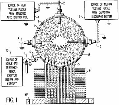
Fig.2 is an elevational view of the primary engine power stroke:

Fig.3 is an elevational view of the primary engine compression stroke:

Fig.4 is a rear elevational view of a six cylinder AEROPS engine:

Fig.5 is a top view of the six cylinder AEROPS engine:

Fig.6 is an electrical schematic of the source of medium-voltage:
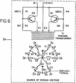
Fig.7 is an electrical schematic of the source of high-voltage:
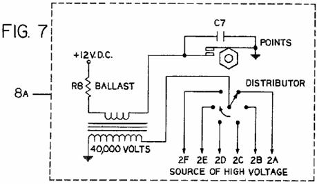
DETAILED DESCRIPTION

Referring to Fig.1 of the drawings, the AEROPS engine comprises a hollow spherical pressure chamber 1 having an insulated high-voltage electrode 2 mounted on the top, an insulated medium-voltage electrode 3 mounted on the right, and an insulated common ground electrode 4 mounted on the left, as shown in this particular view. Electrodes 2, 3 and 4 extend through the wall of the hollow spherical pressure chamber 1 and each electrode forms a pressure seal. A plurality of hollow tubes 5 arranged in a cylindrical pattern extend through the wall of the hollow spherical pressure chamber 1, and each hollow tube is welded to the pressure chamber to form a pressure seal. The opposite ends of hollow tubes 5 extend through the mounting plate MP and are welded likewise to form a pressure seal. A plurality of heat transfer fins 6 are welded at intervals along the length of said hollow tubes 5. A bright reflecting mirror surface 7 is provided on the inner wall of the hollow spherical pressure chamber 1. A source of high-voltage 8 is periodically connected to the insulated high-voltage electrodes 2 and 4. A source of medium-voltage 9 from a discharge capacitor is connected to the insulated medium-voltage electrodes 3 and 4. A source of noble gas mixtures 10, e.g., xenon, krypton, helium and mercury is applied under pressure into the hollow spherical pressure chamber 1 through pressure regulator valve 11 and check valve 12.
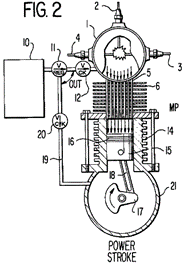
Referring now to Fig.2 of the drawings, the complete assembly 13 shown in Fig.1 is mounted on the top of the cylinder 14 via mounting plate MP. The necessary gaskets or other means are provided to seal the engine and prevent loss of gases into the atmosphere. The piston 15 located within cylinder 14 has several rings 16 which seal against the inner wall of the cylinder. The piston 15 is connected to the crankshaft 17 by connecting rod 18. The source of noble gas mixtures 10 is applied under pressure into the crankcase 21 through pressure regulator valve 11, check valve 12 and capillary tube 19. The piston 15 is now balanced between equal gas pressures. Assuming that the engine is running and the piston 15 is just passing Top-Dead-Centre (TDC), a source of medium-voltage from a capacitor discharge system 9 (Fig.6, a single typical capacitor section) is applied to electrodes 3 and 4. A source of high-voltage pulses from a standard ignition coil 8 (such as shown in Fig.7) is applied to electrodes 2 and 4 and the gases within the hollow spherical pressure chamber 1 are ionised and made electrically conductive. An electrical discharge takes place between electrodes 3 and 4 through the gases in the hollow spherical pressure chamber 1.
The electrical discharge releases high energy photons on many different electromagnetic frequencies. The photons strike the atoms of the various gases, e.g., xenon, krypton, helium and mercury at different electromagnetic frequencies to which each atom is selectively sensitive and the atoms of each gas become excited. The first photons emitted are reflected back into the mass of excited atoms by the reflecting mirror surface 7. This triggers more photons to be released by these atoms, and they are reflected likewise from the mirror surface 7 and strike other atoms into excitation and more photons are released as the chain reaction progresses. The electrons orbiting around the protons of each excited atom increase in speed and expand outward in a new orbital pattern due to an increase in centrifugal force. Consequently, a pressure wave is developed in the gases as the atoms expand and the overall pressure of the gases within the hollow spherical pressure chamber 1 increases. As the gases expand they pass through the hollow tubes 5 and apply pressure on the top of piston 15. The pressure pushes the piston 15 and the force and motion of the piston is transmitted through the connecting rod 18 to the crankshaft 17 rotating it in a clockwise direction. At this point of operation, the power stroke is completed and the capacitor in the medium-voltage capacitor discharge system 9 is discharged. The excited atoms return to normal ground state and the gases return to normal pressure level. The capacitor in the medium-voltage capacitor discharge system 9 is recharged during the time period between (TDC) power strokes.
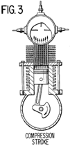
Referring now to Fig.3 of the drawings, the compression stroke of the engine is shown. In this engine cycle the gases above the piston are forced back into the hollow spherical pressure chamber through the tubes of the heat transfer assembly. The gases are cooled as the heat is conducted into the fins of the heat transfer assembly and carried away by an air blast passing through the fins. An example is shown in Fig.4, the centrifugal air pump P providing an air blast upon like fins.
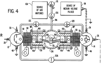
Some of the basic elements of the invention as set forth in Fig.1, Fig.2, and Fig.3 are now shown in Fig.4 and Fig.5 which show complete details of a six-cylinder horizontally-opposed AEROPS engine.
Referring now to Fig.4 and Fig.5 of the drawings. Fig.4 is a view of the rear section of the engine showing the crankshaft, centre axis and two of the horizontally-opposed cylinders. In as much as the rear R, middle M and front F sections of the engine possess identical features, only the rear R engine section will be elaborated upon in detail in order to prevent repetition and in the interest of simplification. The crankshaft 17A consists of three cranks spaced 120 degrees apart in a 360 degree circle as shown. Both connecting rods 18A and 18B are connected to the same crank. Their opposite ends connect to pistons 15A and 15B, located in cylinders 14A and 14B respectively. Each piston has pressure sealing rings 16A and 16B. The hollow spherical pressure chamber assemblies consisting of 1A and 1D are mounted on cylinders 14A and 14B via mounting plates MP. The necessary gaskets are provided as needed to seal the complete engine assemblies from atmospheric pressure.
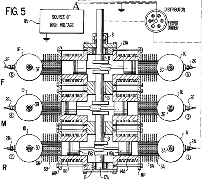
The source of gas mixtures 10A is applied under pressure to pressure regulator valve 11A and flows through check valve 12A, through check valve 12B to the hollow spherical pressure chamber 1A, and through check valve 12C to the hollow spherical pressure chamber 1D. The gas flow network consisting of capillary tubes below point 19A represents the flow of gases to the rear section R of the engine. The middle section M and the front section F both have gas flow networks identical to that consisting of capillary tubes below point 19A, while the gas flow network above is common to all engine sections. Throttle valve 20A and the connecting tubing form a variable bypass between hollow spherical pressure chambers 1A and 1D to control engine speed and power. Engine sections R, M and F each have this bypass throttle network. The three throttle valves have their control shafts ganged together. A source of medium-voltage pulses 9A is connected to medium-voltage electrodes 3A and 3D. In one particular embodiment the medium-voltage is 500 volts. A source of high-voltage pulses 8A is connected to electrode 2A through the distributor as shown. Electrode 4A is connected to common ground. Centrifugal air pumps P force air through heat transfer fins 6A and 6B to cool the gases flowing in the tubes 5A and 5B.
Fig.5 is a top view of the AEROPS engine showing the six cylinders and crankshaft arrangement consisting of the rear R, middle M and front F sections. The crankshaft 17A is mounted on bearings B, and a multiple shaft seal S is provided as well as the necessary seals at other points to prevent loss of gases into the atmosphere. The hollow spherical pressure chambers 1A, 1B, 1C, 1D, 1E and 1F are shown in detail with high-voltage electrodes 2A, 2B, 2C, 2D, 2E, 2F and medium-voltage electrodes 3A, 3B, 3C, 3E and 3F. The common ground electrodes 4A, 4B, 4C, 4D, 4E, 4F are not shown in Fig.5 but are typical of the common ground electrodes 4A and 4D shown in Fig.4. It should be noted that the cranks on crankshaft 17A are so arranged to provide directly opposing cylinders rather than a conventional staggered cylinder design.

Fig.6 is an electrical schematic of the source of medium-voltage 9A. The complete operation of the converter is explained as follows: The battery voltage 12 VDC is applied to transformer T1, which causes currents to pass through resistors R1, R2, R3 and R4. Since it is not possible for these two paths to be exactly equal in resistance, one-half of the primary winding of T1 will have a somewhat higher current flow. Assuming that the current through the upper half of the primary winding is slightly higher than the current through the lower half, the voltages developed in the two feedback windings (the ends connected to R3 and R2) tend to turn transistor Q2 on and transistor Q1 off. The increased conduction of Q2 causes additional current to flow through the lower half of the transformer primary winding. The increase in current induces voltages in the feedback windings which further drives Q2 into conduction and Q1 into cut-off, simultaneously transferring energy to the secondary of T1. When the current through the lower half of the primary winding of T1 reaches a point where it can no longer increase due to the resistance of the primary circuit and saturation of the transformer core, the signal applied to the transistor from the feedback winding drops to zero, thereby turning Q2 off. The current in this portion of the primary winding drops immediately, causing a collapse of the field about the windings of T1. This collapse in field flux, cutting across all of the windings in the transformer, develops voltages in the transformer windings that are opposite in polarity to the voltages developed by the original field. This new voltage now drives Q2 into cut-off and drives Q1 into conduction. The collapsing field simultaneously delivers power to the secondary windings L1, L2, L3, L4, L5 and L6. The output voltage of each winding is connected through resistors R5, R6 and R7 and diode rectifiers D1, D2, D3, D4, D5 and D6, respectively, whereby capacitors C1, C2, C3, C4, C5 and C6 are charged with a medium-voltage potential of the polarity shown. The output voltage is made available at points 3A, 3B, 3C, 3D, 3E and 3F which are connected to the respective medium-voltage electrodes on the engine shown in Fig.4 and Fig.5.
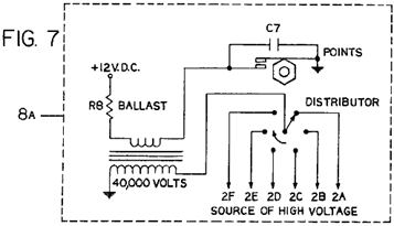
Referring now
to Fig.7 of the drawings, a
conventional "
Referring again to Fig.4 and Fig.5 of the drawings, the operation of the engine is as follows: Assuming that a source of noble gas mixtures, e.g., xenon, krypton, helium and mercury is applied under pressure to the hollow spherical pressure chambers 1A, 1B, 1C, 1D, 1E and 1F and internally to the crankcase 21A through pressure regulator valve 11A and check valves 12A, 12B and 12C; and the source of medium-voltage 9A is applied to electrodes 3A, 3B, 3C, 3D, 3E and 3F; and a source of high-voltage pulse 8A is applied to electrode 2A through the timing distributor, the gas mixtures in the hollow spherical pressure chamber 1A is ionised and an electrical discharge occurs immediately between electrodes 3A and 4A.
High-energy photons are released on many different electromagnetic frequencies. The photons strike the atoms of the various gases, e.g., xenon, krypton, helium and mercury at different electromagnetic frequencies to which each is particularly sensitive and the atoms of each gas become excited. The first photons emitted are reflected back into the mass of excited atoms by the internal reflecting mirror surface on the inside wall of the hollow spherical pressure chamber 1A. This triggers more photons to be released by these atoms and they are reflected likewise from the mirror surface and strike other atoms into excitation and more photons are released as the chain reaction progresses. The electrons orbiting around the protons of each excited atom in the hollow spherical pressure chamber 1A increase in speed and expand outward in a new orbital pattern due to an increase in centrifugal force. Consequently, a pressure wave is developed in the gases as the atoms expand and the overall pressure of the gases within the hollow spherical pressure chamber 1A increases.
As the gases expand they pass through the hollow tubes 5A applying pressure on the top of piston 15A. The pressure applied to piston 15A is transmitted through connecting rod 18A to the crankshaft 17A rotating it in a clockwise direction. As the crankshaft 17A rotates it pushes piston 15B via connecting rod 18B in the direction of a compression stroke, forcing the gases on the top of the piston through hollow tubes 5B into the hollow spherical pressure chamber 1D. As the gases pass through the hollow tubes 5A and 5B the heat contained in the gases is conducted into the heat transfer fins 6A and 6B, where it is dissipated by a blast of air passing through said fins from the centrifugal air pumps P. At this point of operation the power stroke of piston 15A is completed and the capacitor in the medium-voltage capacitor discharge system 9A is discharged. The excited atoms return to normal ground state and the gases return to normal pressure level. The capacitor in the medium-voltage capacitor discharge system 9A is recharged during the time period between the power strokes of piston 15A.
The above power stroke cycle occurs exactly the same in the remaining cylinders as the high-voltage firing order progresses in respect to the position of the distributor switch. In as much as the AEROPS engine delivers six power strokes per single crankshaft revolution, the crankshaft drives the distributor rotor at a one to one shaft ratio. The complete high-voltage firing order is 1, 4, 5, 2, 3, 6, whereas, the high-voltage is applied to electrodes 2A, 2B, 2C, 2D, 2E and 2F respectively. A means of controlling engine speed and power is provided by a plurality of throttle control valves and connecting tubes which form a bypass between opposing hollow spherical pressure chambers of each engine section.
The AEROPS engine as described above provides a sealed unit power source which has no atmospheric air intake nor exhaust emission and is therefore pollution free.
Floyd Sweet
Recently, some additional information on Floyd Sweet's device, has been released publicly by an associate of Floyd's who goes just by his first name of "Maurice" and who, having reached the age of seventy has decided that it is time to release this additional information.
Maurice says:
After observing the comments made over the past year regarding the Sweet-VTA
Energy Device, I decided to "come out of the woodwork" and explain
what basically is NOT known regarding Floyd Sweet ("Sparky") and his
energy device.
Keep in mind that
I am 70 years old, quite computer illiterate, my background Being mainly
Political Science (Graduate Degree); consulting with State Legislatures; Mental
Health (former Executive Director of five clinics); and, acquiring Venture
Capital for High Tech. Equipment (such as medical equipment) and various
Projects. My story is very unusual and
strange, but, nevertheless TRUE! At my
age I have no one to impress with what I am about to tell you. My only interest is to correct error where
possible and to make certain information known!
Remember, that I
have never had any education in electronics.
This was a real advantage for me because I did not have any electrical
principles which I had to UN-LEARN in anything that Floyd told us. Unfortunately, one of my brothers who trained
for 35 years in electronics was "blown away" when Floyd told him that
"he needed to reverse the concepts which he was taught about the action of
an electron and treat it like it was positive". Therefore, for Sparky's modelling, electrons
were flowing and acting in the opposite direction to what was normally modelled
by a trained physicist. See what I
mean? The Dean of the School of Science
of MIT that verified that Sparky had an MSEE degree and came third in his class
of more than two hundred.
Hopefully sincere
researchers will be able to obtain some useful information in what I attempt to
explain in the future that will help them to duplicate what Floyd had. In this respect, one day after Floyd had
repeatedly asked me: "What is this device Maurice?" and I repeatedly
gave him the wrong answer, saying that it was an energy device, I finally
realised that what was important to him was that he considered the device to be
a TIME MACHINE - his emphasis was NOT on the energy. He told me never to forget that the most
important thing was that the device was a "Time Machine".
Maurice draws
attention to the fact that Floyd Sweet graduated as an M.S.E.E. from the
Massachusetts Institute of Technology in 1969 and his thesis "Dynamics of
Magnetic Domains" is considered by the M.I.T. scientific community to be
unparalleled in magnetic concepts. He
received the coveted Dean's Award for his scientific research and his academic
level in Electrical Engineering achievement ranks third in the history of the
Maurice says: In
about 1988 John, who my two brothers and I were involved with in the High Tech
field realised that my brother, who was a Doctor (Doctor brother), was
interested in negative energy devices for the treatment of the physical body
(similar to Rife/Tesla Frequency Machines).
John had formerly been employed at NASA with Floyd Sweet. John lived in
My
doctor brother and I were introduced to Floyd by John and we waited patiently
for the time when we could see the VTA device.
We saw it on the table at his house during various visits but it was not
operating. Floyd was like many inventors
who played games with you. Each time we
would drive 13 hours to see him thinking we could see the device operating, but
he would have some excuse for not turning it on, or he would just ignore the
purpose of our visit.
On
one visit, I looked over at Floyd and he was “showing off” his Barium Ferrite
bar magnet. The magnet was approximately
1/2” thick, 7” long and 3” wide. He had
a small piece of metal that was standing on the top of the magnet at a 45
degree angle. As I recall, he claimed that the 45 degree angle was needed in
the treatment of the magnet so that it could capture Scalar waves. The magnets were mainly functioning as a
“gate” for the Scalar waves.
Additionally, if you placed a piece of thin “flexible” (ribbon type)
metal flat on the top of the magnet, the middle of the “ribbon metal” would be
“sucked down” flat at the middle of the magnet and both ends of the “ribbon
metal” would be bowed-up at each end of the magnet. Also, I came to understand from another
inventor that we introduced later on to Floyd that the “figure eight” design
(flux flow?) on the top of the magnet played an important part in the
functioning of the magnet - I don’t really know about the concept and can’t
relay any additional information.
On
another visit, Floyd demonstrated the flowing flux of the magnet. He had a TV monitor and he would place the
magnet by the screen and you could see all the beautiful colours of the flux as
it moved across the monitor screen. My
electronics brother told me that Floyd had told him that he had a way of treating
the magnet by calibrating the Scalar wave angle coming in using the TV
monitor. A side note is that Floyd
delighted in telling people, when they asked how he treated his magnets, they
should get the magnets real hot first.
This apparently “screwed up” the magnetism and he enjoyed doing this for
some weird reason!
Finally,
after 12 trips across the
When
we first started to visit Floyd, our phones were all “tapped” - I do not know
by whom. My electronics brother worked
full-time with the Air National Guard and his specialty was electronic
Security, Crypto, etc. tied in with SAC bases in our area and the surrounding
States. Additionally, he had set-up the
“clean room” for the President of the
I
give you the above information so that you can understand the seriousness of
what we were involved with.
Floyd’s
Energy Device was mainly three things:
(1)
It was a healing device - negative electricity - negative time. In theory, you could re-set the template in
your DNA with this energy source and therefore cleanse the body of all
impurities that your ancestors had acquired over time. Additionally, you could kill current disease
(virus/bacteria) in the body by using the right frequencies, and this did not
disturb any other body cells. This is
why Floyd needed my doctor brother to help him arrive at the proper medical
protocol for using his technology.
Additionally, if you note in the Payroll Expenses attachment of this
e-mail, a one-line item of expenditure is for AIDS-related materials in which
Floyd and my doctor brother had a real interest. My doctor brother had an agreement with Floyd
to build three medical interferometers which would all have a noble gas plasma
inside them. I actually witnessed one of
these devices in operation. At the end
of the (approximately 20 inch long) tube-like structure you could feel a
pulsing being emitted at the end of the tube on to whichever part of the body
you wanted treated. My doctor brother
had ordered two Interferometers from Floyd which were about 4 feet long.
(2)
The VTA energy device is probably the world’s worst weapon. Floyd claimed that like Nicola Tesla, you
could cause “artificial earthquakes” - besides destroying buildings. As I understood from people in the
intelligence world, which we de-briefed after we saw the device operate, three
countries have what is called the “Tesla Cannon”;
(3)
The device was an Energy source for the home (could change negative energy to
positive energy). It was also an energy
source for the car and many other purposes.
The cost of building one of these energy devices was only about US
$200.00 - incredible!
Description of the VTA
device:
On
the day that we finally got to see the device operating, my doctor brother and
I had finally convinced my electronics brother to accompany us to Sherman Oaks,
California to see the demonstration. My
doctor brother and I had made ALL the preliminary trips to see Floyd minus our
electronics brother because he was literally a “doubting Thomas”, being heavily
involved in the electronics field and full of Maxwell’s Theories of
electronics, etc. Yes, you could say
that he was a traditional electronics person.
But, for this reason, we needed my electronics brother to be our
DEBUNKER in case the device was not what it was portrayed to be. We had one other witness "Gary", an
associate of mine who was to bring in the venture capital funding if the device
proved to be as good as claimed.
The
day when we witnessed the VTA device operating is a day which I shall never
forget. To actually see a device
working, which cost only $200 dollars to make and which could create all the
clean energy you would ever need, was “awesome”. I know I have been “altered” ever since
knowing that such a device existed. Now
for a brief description of the Device:
These
are not exact measurements but only approximations. The device was on what I believe to be
"Plexi glass" (acrylic).
Nothing was hidden. You could see
everything, top and bottom through the plastic.
The Plexi glass structure was approximately 18” square. We were allowed to pick-up the device and
carry it around Floyd’s living room so you could see that there were no other
electrical connections to it.
On
top of the Plexi glass case there were three toroidal coils wound with thin
windings of varnished copper wire. There
were two barium ferrite bar magnets (approx. 7”x 3”x 1/2”). Present was a volt meter which displayed
120v when the device was turned on.
Also, there was an ampere meter which measured the electrical currents
flowing when Floyd switched different things on-and-off during the
demonstration. The items used for load
demonstration included the burner part of the stove, a hair dryer, a fan, and
five one-hundred watt globe lights. The
fascinating thing to me about the light demo was that the lights had a glow
like the overhead lights in your kitchen - a very soft, COOL appearance. Not the look of a traditional bright light
bulb such as you have in your lamp on a traditional night stand.
I
forgot to mention that the device was started by attaching a 9-volt battery
which, I understand, started the magnetic flux in motion. Floyd would then connect the “pigtail” on the
device and it would become just one circular energy unit.
As
Floyd put more load on the device, the ambient temperature around the device
(coils) would start to get lower.
Additionally, depending on how much load you added, the device would
start to lose some of its weight and you then had levitation beginning to take
place. I should note at this point that
on one meeting with Floyd, his wife Rose, used some expletives when telling how
one day, Floyd kept adding more-and-more load to the device and he almost
“brought down” the Apartment Complex he lived in at Sherman Oaks. He turned off the equipment, went out on his
patio and pretended that it was a
The Rest of The Story:
You
are probably wondering what the article on Ron Brandt is about. It’s a long story, but after I moved Ron and
his laboratory all the way from the mouth of Zion's National Park to
“someplace” Oregon to hide him out - he was using “Tachyon Beams" with his
medical equipment and after only a couple of minutes the “Black Helicopters”
would show up - soooo at my doctor brother’s
request I moved Ron to Oregon. At
the time I thought Ron was a “real flake” because when I helped him forward his
mail from a small town in
Well,
guess what happened a few days later? The largest earthquake in many years in
that particular location took place and it even wiped out the
Now,
why am I giving you all this preliminary information regarding Ron Brandt? Well it seems that Ron has a Magnet Motor
which weighs only 75 pounds and which can generate power equivalent to that of
a 300 horsepower internal combustion engine.
Also, the motor can be a retro-fit in any existing car without the need
to design a whole new car. This is the
connection I will explain later regarding Ron who could not even spell
“electric” and Floyd who was placed 3rd in
all the inventions to ever come out of MIT - All I can say is “WOW”!
EVENTS SURROUNDING
FLOYD’S DEATH:
I
will now leave it up to you to decide whether or not Floyd died of natural
causes or was “taken out” by some person, group, or some Government.
In
the summer of 1994, my doctor brother suddenly “passed out” at one of our
Venture Capital meetings and was rushed to the hospital. After an MRI of his head, it was discovered
that he had a brain tumour and it was of the worst kind (very fast growing). This seemed impossible as my doctor brother
had always monitored his body daily as he did an occasional experiment on
himself with certain medicines. By 11th
November 1994, my doctor brother had died.
He told us prior to death that “they” (whoever "they" were)
had succeeded in placing the fastest growing cancer tumour into his brain -
How? - I have no idea! I never did find
out. What is important to the
free-energy field was that my doctor brother was in daily contact with Floyd
and his Associates regarding the energy devices. I was not that important and basically only
accompanied my doctor brother to meetings and kind of “got lost in the
woodwork”. Intellectually, I really was
not a threat to anyone. I was only there
at meetings to help acquire venture capital.
On
the very day that my doctor brother died, my electronics brother and I were at
the home of John, (Floyd’s Associate
from NASA) who for some strange reason had followed my brothers and I to our
home city where we lived, bought a home and took up residence there. We did not complain as he was our go-between
with Floyd. But the move still seemed
strange to me. The reason my electronics
brother and I were with John is that John had arranged a conference call with
Floyd and us, to see if there was a possibility for Floyd to make some type of
energy device which could power the magnet motor that Ron Brandt had. My brothers and I had all the contractual
rights to Ron’s Magnet Motor which could be used in any car. I thought to myself that now I can really
find out how “real” Ron (who could not even spell “electric”) was when I
matched him up with Floyd from MIT. I
could not believe what I heard as Floyd and Ron conversed at the highest
electronic levels - "who the 'hell' is Ron?" I thought. Floyd agreed that he would have no problem
doing the prototype for Ron’s Magnet Motor to power the car.
Floyd
mainly worked with my electronics brother on this project as Floyd needed old
vacuum tubes which my electronics brother had to acquire for the device and my
electronics brother was a real “bench” person which Floyd seemed to favour over
academic Electrical Engineers.
During
the Spring of 1995, while Floyd was working on our energy device for the car,
John (from NASA) and Floyd were elated that there was supposed to be an
announcement from the White House regarding Floyd’s VTA Energy Device. It seems that Floyd was a past friend of
Senator John Glen (the former NASA astronaut) and he had given Glen one of the
energy devices. Unfortunately, Glen gave
the device to the Department of Energy, who, according to Floyd, passed the
device on to General Motors. Floyd was
furious and as I understood Floyd was then going to sue GM for two hundred
million dollars. As far as I know Floyd
never got the device back. I will always
remember the extreme disappointment on the faces of Floyd and John when they
realised that the trip to
In
July 1995, Floyd let us know that the Energy Device was finished and we were to
take possession of it. Floyd now lived in
Desert Palms,
Floyd
called us the day before we were to leave and asked us if he could keep the
device for a couple of extra days. He
said he had “someone” coming (I thought he said
A
day later, at about 7:00 am Pacific time, there was a frantic call from Floyd’s
wife Violet (Floyd’s wife Rose had died and he had re-married) to my
electronics brother’s house. My
electronics brother was not at home and my sister-in-law, his wife, took the
call from Violet. Violet was very
traumatised when she told my sister-in-law that Floyd was dead. There was a lot of shouting going on in the
background. The people who were there
claimed they were from the FBI and that Floyd’s equipment belonged to them. Rose was extremely confused with the death of
Floyd and people she had never seen before taking all the equipment out of her
house to waiting vans. She asked my
sister-in-law what to do and my sister-in-law had NO idea as she was not aware
of what my brothers and I had going on!
Violet
also said that about 5:00 pm the previous night, two men whom she had never
seen before, showed up to see Floyd.
Floyd was with them for a period of time and then they left. At about 8:00 pm, Floyd was having a cup of
coffee when he fell out of the chair on to the floor. She called for an ambulance and when they
arrived they would not let her ride with them.
Violet was 75 years old and didn’t drive. About twenty minutes later the ambulance
called back to Violet and told her they didn’t think Floyd was going to “make
it”!! As I understand it, Floyd’s body
was cremated. How soon afterwards, I
don’t know. The end result for my
brothers and I is that ALL of our energy equipment that Floyd made for us was
taken - By Whom??
Who
were the two men who met with Floyd a few hours before his death? Was anything put in Floyd’s coffee by these
men? Violet said she had never seen them
before and they seemed strange!
Why
could Violet not go with her husband in the ambulance? I have seen it happen many times when family
is allowed, especially where age is concerned!
How
did the FBI (if that is who they were) know that Floyd was dead and show up in
the very early morning (about 6:00 am) just hours after he died late at night?
YOU BE THE JUDGE - ALL I KNOW IS THAT ALL OF OUR ENERGY DEVICES (MEDICAL
AND CAR-MAGNET MOTOR) ARE GONE!!! WHERE
ARE THEY AND WHO ARE THE ONES RESPONSIBLE FOR TAKING THEM ??
Here are some of the known facts about Floyd's energy device:
The invention is a
unified-field device and so combines both electromagnetic and gravitational
effects in the same unit. For a tiny
power input of just 0.31 milliwatt, the unit produces over 500 watts of output
power, which is an energy gain of more than 1,500,000. The prototype, has no moving parts, is about
6" x 6" x 4" in size and taps an inexhaustible source of
energy. To date, up to one kilowatt of
power has been produced in actual tests which required only tiny input power to
make the device operate.
Our normal
day-to-day energy is "positive energy". The energy produced by Floyd's device is
"negative energy" but in spite of this, it powers ordinary equipment,
producing light and heat as normal. A
device like this has to have a major impact on the world as we know it,
because:
1. It
can be easily built. The components are
quite ordinary and the cost of the materials in the demonstration prototype was
only a few hundred US dollars and it was constructed in just a few hours, using
simple tools and equipment.
2. The
test results are so impressive that there can be no question of errors of
measurement when the energy gain is of the order of 1,500,000 times.
3. It
demonstrates with laboratory precision that the 'law' of Conservation of Energy
does not appear to apply during the operation of this device, which is
something which most scientists have difficulty in accepting.
The device has
very high performance. When a
1-milliwatt 60Hz sine wave is fed into it, the out put powers 500 watts of
standard mains-voltage light bulbs, producing both heat and light. The device has a positive-feedback loop so
it's gain is depends directly on the output load and the input power remains
unchanged. So to increase the output
power, all that is necessary is to connect extra light bulbs or equipment across
the output.
When a motor was
connected in addition to the light bulbs, the motor ran perfectly well under
load and the light bulbs remained as bright as ever. Because it is a "cold electricity"
device, the wires feeding the load can be very much smaller in diameter than
would be normal for the load and these wires run cold at all times. When the power hits the resistance of the
filaments of the light bulbs, it converts into conventional "hot
electricity" and the filaments perform in exactly the same way as they do
when powered by "hot electricity".
In 1988, Floyd produced a paper which he considered to be very important. The following text is an attempt to reproduce the content his highly mathematical style of presentation. If you are not into complicated mathematical presentations, then just move on past and don't worry about the following technical material, or alternatively, take a quick skim through it and don't bother with the maths. Floyd says:
What is thought of
as "empty space" actually contains almost everything in the universe.
It is home to all kinds of invisible
energy fields and is seething with all kinds of very real forces.
Every kind of
matter produces an energy field and these energy fields interact with each
other in many complicated ways, producing all sorts of additional effects. These energy fields are the "stuff"
of space, or as it is sometimes described, "the virtual vacuum". Space is packed full of all sorts of things
but because it does not contain air, we tend to think that there is nothing at
all in it. Most people think that
"vacuum" means "without air" but when scientists speak of
space as "the vacuum" they do not mean that at all, and they use the
word "vacuum" to describe to describe (loosely speaking) the place which
is between the stars and planets of the universe, and Floyd refers to that vast
place as "the vacuum", so please don't think that it has anything to
do with air, as it definitely doesn't.
Floyd says: We all
think that we know what light is, but the reality is that a particle of light
is nothing more than a large interference in the electromagnetic field. Unless it interacts with matter or with
another field, any electromagnetic field with not be changed in any way by the
vacuum. Electromagnetic fields are a
fundamental part of the structure of the vacuum itself. The whole universe is permeated by a constant
magnetic field. That field is made up of
countless numbers of North and South pole magnets in a completely random
scatter.
Einstein has
pointed out that E = mC2 which is one way of saying that energy and matter are
interchangeable (or are two different faces of the same thing). The energy everywhere in the universe is so
great that new particles of matter pop into existence and drop back into their
energy form many trillions of times per second.
Actually, they exist for such a very short time that calling them
"particles" is not really appropriate, so perhaps "virtual
particles" might be a better description.
However, if we
generate a moving magnetic field, it alters the random nature of this energy in
the tiny part of the vacuum where we happen to be, and the vacuum energy
becomes much less random and allows a very large amount of vacuum energy to be
drawn into our equipment and do what we think of as "useful work" -
producing heat and light, powering motors and vehicles, etc. This was proved in laboratory experiments
during the week of 19th June 1988 and it is the underlying operating principle
of my "Phase-Conjugated Vacuum Triode" device.
The energy
produced by this device is "negative energy" which is the reverse of
the energy with which we are familiar.
The spark caused by a short-circuit in a negative energy system is
excessively bright and cold and it produces a barely audible hiss with no
explosive force. Melting of wires does
not occur and this type of negative current passes through the human body with
only the feeling of a chill.
Wires which carry
a lot of negative energy remain cool at all times and so tiny wires can feed
equipment with hundreds of watts of power.
This has been demonstrated in the laboratory and the source of energy is
unlimited as it is the virtual vacuum of space itself.
The Nature of Space:
Space itself is
the ability to accommodate energy.
Consider for a moment, the following illustration:
A signal (energy) is transmitted from point
"A" to point "B" which are separated by a finite
distance. Consider three periods of
time:
1. The signal is
launched from point A.
2. The signal
resides in the space between point A and point B.
3. The signal arrives at point B.
If 3. occurs
simultaneously with 1. we say that the signal has travelled at infinite
velocity. If that were the case, then
the signal never resided in the intervening space and therefore there must be
no space between point A and point B and so both points A and B must be at the
same location. For real space to exist
between the two points, it is necessary that a signal moving between them has
to get "lost" to both points, that is, out of touch with both points
for a finite period of time.
Now, we know that
for real space to exist between two points, a signal passing between them has
to move at a finite speed between them and if it can't do that, then there
can't be any space between them. If
space can't accommodate a signal passing between two points, then it has no
function and no reality. We are left
then with the only real space, the home of the real and virtual vacuum - space
which supports a finite, non-zero signal velocity.
A similar argument
applies to the impedance of space. A
medium can only accommodate positive energy if the medium resists it to a
reasonable degree. Neither an infinitely
strong spring nor an infinitely weak spring can absorb energy by being
compressed. Neither an infinitely large
mass nor an infinitely small mass can absorb or accommodate energy imparted by
a collision and the same holds true for space.
Energy cannot enter a space of zero impedance any more than a force can
bear on a mass of zero magnitude.
Similarly, energy could not enter space which has an infinite
impedance. It follows therefore, that
real space must have:
1. Finite
propagation velocity and
2. Finite
impedance.
Another way of
looking at this is instead of considering the actual speed of propagation of a
signal through space, to consider the length of time "t" which it
takes the signal to pass through that part of space. We can think of a section of space as being,
say, 1 nanosecond wide if it takes a signal 1 nanosecond to traverse it. That is, the energy or signal entering that
part of space, leaves it again 1 nanosecond later. Signal propagation speed in the space in
which we live is at the speed of light.
General Description of Energy Transfer:
Consider energy
flowing straight and level down a transmission line. The energy does not "know" the
width of the channel through which it is passing. If the energy flow reaches a point where the
conductivity of the channel lowers but the size and shape of the channel remain
the same, then not as much energy can flow and some gets reflected back along
the channel. The energy current will not
"know" if (a) the conductivity has changed or (b) the geometry has
changed. The energy current can change
direction very easily and so as far as it is concerned, the change caused by
(a) is equivalent to the change caused by (b).
The channel
through which the energy flows has width and height and the width divided by
the height is called the "aspect ratio" of the channel. Energy current has an aspect ratio and if
that aspect ratio is forced to change, then some of the flowing energy will
reflect so as to keep the overall
aspect ratio unchanged.
The aspect ratio
of energy current is much like the aspect ratio of space itself. While the aspect ratio of space itself can
change, it's fundamental velocity of "C" the speed of light in space
can't really change. That speed is just
our way of visualising time delay when energy resides in a region of
space. Uniform space has only two
parameters:
(1)
Aspect ratio and
(2)
Time delay
Aspect ratio
defines the shape (but not the magnitude) of any energy flow which enters a
given region of space. Velocity or
length define the time during which that energy can be accommodated in a region
of space.
Does an energy
flow travel unimpeded through an interface, or does a large part of it get
reflected? Space has quiet zones through
which energy glides virtually unreflected.
It also has noisy zones where the energy current becomes incoherent,
bounces around and splits apart. These
noisy zones in space either have either rapidly changing geometry or rapidly
changing impedance.
Electromagnetic Energy:
The rate of flow
of energy through a surface can be calculated using "E" the Electric
field, and "H" the Magnetic field intensity. The energy flow through space is E x H per
unit area (of it's "conduit's" cross-sectional area) and the energy
density is E x H / C where C is the
speed of light in space.
If there happen to
be two signals of exactly the same strength, passing through each other in
opposite directions in such a way that their "H" fields cancel out,
then if each has a strength of E/2 and H/2, the energy density will be E x H /
2C and it will have the appearance of a steady E-field. In the same way, if the E fields cancel out,
the result will appear to be a steady "H" field.
Modern physics is
based on the faulty assumption that electromagnetics contains two kinds of
energy: electric and magnetic. This
leads to the Baroque view of physical reality.
Under that view, energy seems to be associated with the square of the
field intensity, rather than a more reasonable view that it is directly to the
field intensity. It is worth remembering
that neither Einstein nor most modern physicists were, or are, familiar with
the concept of "energy current" described here. However, their work still survives by
ignoring the energy current concept, scalar electromagnetics, the works of Tom
Bearden, kaluza-Klein and others who dispute Heaviside's interpretations of
Maxwell's equations.
The Fallacy of Displacement Current:
Conventional
electromagnetic theory proposes that when an electric current flows down a wire
into a capacitor, it spreads out across the plate, producing an electric charge
on the plate which in turn, leads to an electric field between the plates of
the capacitor. The valuable concept of
continuity is then retained by postulating a displacement current "after
Maxwell". This current is a
manipulation of the electric field "E" between the plates of the
capacitor, the field having the characteristics of electric current, thus
completing the flow of electricity in the circuit. This approach allows Kirchoff's laws and
other valuable concepts to be retained even though superficially, it appears
that at the capacitor there is a break in the continuous flow of electric
current.
The flaw in this
model appears when we notice that we notice that the current entered the
capacitor at only one point on the capacitor plate. We are then left with the major difficulty of
explaining how the electric charge flowing down the wire suddenly distributes
itself uniformly across the entire capacitor plate at a velocity in excess of
the speed of light. This paradoxical
situation is created by a flaw in the
basic model. Work in high-speed
logic carried out by Ivor Catt has shown that the model of lumped capacitance
is faulty and displacement current is an artefact of the faulty model. Since any capacitor behaves in a similar way
to a transmission line, it is no more necessary to postulate a displacement
current for the capacitor than it is necessary to do so for a transmission
line. The removal of "displacement
current" from electromagnetic theory has been based on arguments which are
independent of the classic dispute over whether the electric current causes the
electromagnetic field or vice versa.
The Motional E-Field:
Of all of the
known fields; electric, magnetic, gravitational and motional E-field, the only
ones incapable of being shielded against are the induced motional E-field and
the gravitational field. The nature of
the motionally-induced electric field is quite unique. In order to understand it more fully, we must
start by discarding a few misleading ideas.
When magnetic flux is moved perpendicularly across a conductor, an
electromotive force ("e.m.f.") is electromagnetically induced
"within" the conductor.
"Within" is a phrase which comes from the common idea of
comparing the flow of electric current within a wire to the flow of water in a
pipe. This is a most misleading
comparison. The true phenomenon taking
place has little been thought of as involving the production of a spatially-
distributed electric field. We can see
that the model's origins are likely to have arising from the operation called
"flux cutting" which is a most misleading term. A better term "time-varying flux
modulation" does not imply any separation of lines of flux. Truly, lines of flux always form closed loops
and are expressed mathematically as line integrals.
It is a fallacy to
use the term "cutting" which implies time-varying separation which
does not in fact ever occur. A
motionally-induced E-field is actually created within the space occupied by the
moving magnetic flux described above.
The field is there whether or not a conductor is present in the
space. In terms of a definition, we can
say that when magnetic flux of vector intensity B-bar is moved across a region
of space with vector velocity V-bar, an electromagnetically induced electric
field vector B x V appears in the space at right angles to both B-bar and
V-bar. Therefore:
E
= B-bar x V-bar . . . . . . . . . . . . . . . . . . . (1)
It is this field
which is related to gravity and which is virtually unshieldable. This field may be called the Motional
E-field. According to Tom Bearden,
"It seems that the charged particles in
the atom act like tiny magnets and their motion in the space surrounding the
atom would create this motional E-field". The fields created by both the positive and
negative charges would cancel to some degree, but due to the high orbital velocity
of the negative electron relative to that of the positive proton, the induced
field of the electron would dominate the resulting field. The field produced as a result of these
charges would vary in proportion to the inverse square of the distance as
gravity does. The field produced by the
translational motion of the charges would vary inversely as the cube of
distance. This concept totally unites
the electromagnetic and gravitational field theories and accounts for the
strong and weak force within the atom.
Field Super-Position and the Vacuum Triode:
Electromagnetic
induction with no measurable magnetic field is not new. It is well known that in the space
surrounding a properly wound toroidal coil, there is no magnetic field. This is due to the superposition of the
fields. However, when alternating
current is surging through a transformer, an electric field surrounds it. When we apply the principle of super-position
to the vacuum triode, it becomes more obvious how the device is operating.
The principle of
super-position states that "in order to calculate the resultant intensity
of superimposed fields, each field must be dealt with individually as though
the others were not present" The
resultant is produced by the vector addition of each of the fields considered
on its own. Consider for a moment, the
construction of the triode which includes two bi-filar coils located within the
fields of two conditioned magnets. When
the current in one half of the conductors in the coils (that is, just one strand
of the twin windings in each coil) is increasing, both the current and the
magnetic field follow the right-hand rule.
The resulting motional E-field would be vertical to both and directed
inwards. At the same time, the current
in the other strand of each winding is decreasing and both the current and the
magnetic field also follow the right-hand rule.
The resulting motional E-field is again vertical to both, and directed
inwards. So, the resultant combined
field intensity is double the intensity produced by either one of the
conductors considered on its own.
Expressed mathematically, this is:
E
= (B x V) + (-B x -V) or
E
= 2 (B x V) . . . . . . . . . . . . . . . . . . . . . . . (2)
Where: E is the electric field intensity
B is the magnetic field intensity
and
V is the electron drift velocity
(B x V), the first
term in the equation, represents the flow of the magnetic field when the
electrons are moving in one direction, while (-B x -V), the second term in the
equation, defines the flow of the magnetic field when the electrons are moving
in the other direction. This indicates
that field intensity is directly proportional to the square of the current
required by the load placed on the device.
This is due to it's proportional relationship with the virtual value of
the magnetic field which theory states is proportional to the current. Electrometer readings were always close to
parabolic, indicating that the source was of infinite capacity. It was further determined through experiment,
that the magnetic field does not change with temperature. Also, there is no reason yet identified,
which would lead one to believe that electron drift velocity changes. It has been found remarkable that the vacuum
triode runs approximately 20OF below ambient.
Induced Electromotive Force - Positive
Energy:
When an e.m.f.
("electromotive force") is applied to a closed metallic circuit,
current flows. The e.m.f. along a closed
path "C" in space is defined as the work per unit charge (that is, W
/ Q) done by the electromagnetic fields on a small test charge moved along path
C. Since work is the line integral of
Force ("F"), the work per unit charge is the line integral of force
per unit charge (in
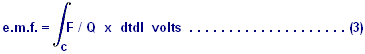
The scalar
product "(F/Q) x dtdl" is the product of (F/Q) x Cosθ
x dl where θ denotes the angle between the
vectors F/Q and dl.
The electric force per unit charge is the electric field intensity
("E") in volts per metre. The
magnetic force per unit charge is V x B where "V" denotes the
velocity of the test charge in metres per second and "B" denotes the
magnetic flux density in webers per metre squared. In terms of the smaller angle θ between V and B, the cross
product of V and B is a vector having the magnitude VBSinθ.
The direction of vector V x B is at right angles to the plane which
contains vectors V and B in accordance with the right-hand rule (that is, V x B
is in the direction of the thumb while the fingers curl through the angle θ from V towards B). Since the total force per unit charge is E +
VB, the total e.m.f. in terms of the fields is:
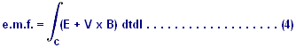
It appears from
equation (4) that the e.m.f. depends on the forward velocity with which the
test charge moves along the path C.
This, however, is not the case.
If V and dl in equation (4) have the same direction, then their
associated scalar product is zero. So,
only the component of V which is not aligned with dl (that is, with θ = 0), can contribute
to the e.m.f. This component has value
only if the differential path length dl has a sideways motion. So, V in equation (4), represents the
sideways motion of dl, if there is any.
The fields E and B in equation (4) could well be represented as
functions of time as well as functions of the space co-ordinates. In addition, the velocity V of each
differential path length dl, may vary with time. However, equation (4) correctly expresses the
e.m.f. or voltage drop along path C as a function of time. That component of the e.m.f. consisting of
the line integral V x B is the motional E-field since it has value only when
path C is ,moving through a magnetic field, traversing lines of magnetic flux. For stationary paths, there is no motional
E-field and the voltage drop is simply the integral of the electric field
"E". Devices which separate
charges, generate e.m.f.s and a familiar example of this is a battery which
utilises chemical forces to separate charge.
Other examples include the heating of a thermocouple, exposure of a
photovoltaic cell to incident light or the rubbing together of different
material to produce electrostatic charge separation. Electric fields are also produced by
time-varying magnetic fields. This
principle is already exploited extensively in the production of electrical
power by the utility companies.
The line integral
of electric field intensity "E" around any closed path "C"
equals -dφ/dt where φ represents the magnetic
flux over any surface "S" having the closed path "C" as
it's contour. The positive side of the
surface S and the direction of the line integral around contour C, are related
by the right-hand rule (the curled fingers are oriented so as to point around
the loop in the direction of integration and the extended thumb points out the
positive side of the surface S). The
magnetic flux φ is the surface integral of magnetic flux density
"B" as shown here:
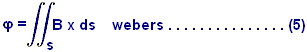
In Equation (5),
the vector differential surface "ds" has an area of ds and in
direction, it is perpendicular to the plane of ds, projecting out of the
positive side of that surface. The
partial time derivative of φ is defined as:
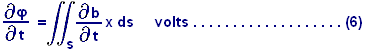
This is referred
to as the magnetic current through surface S. For a moving surface S, the limits of the
surface integral in equation (6) are functions of time, but the equation still
applies. It is important to clarify at
this point, that when we evaluate the value of dφ/dt over a surface which is moving in proximity to magnetic
field activity, we treat the surface as though it were stationary for the
instant under consideration. The
partial time derivative of φ, is the time rate of
change of flux through surface S, due only to the changing magnetic field
density B. Any increase of φ due to
the motion of the surface in the B-field, is not included in that
calculation.
Continuing this discussion leads us to note that an electric field
must be present in any region containing a time-varying magnetic field. This is shown by the following equation:
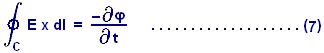
In this equation, φ is the magnetic flux in webers out of the positive side of
any surface having path C as its contour.
Combining equations (7) and (4), we are able to calculate the e.m.f.
about a closed path C as shown here:

or in another
form:

So, the e.m.f. around
a closed path consists in general of two components. The component dφ/dt is the variational e.m.f.
and the second component is the motional E-field. In equation (9), (V x B)dl can, by means of a
vector identity, be replaced with B x (V x dl)A. V is the sideways velocity of d: the vector V
x dl has magnitude Vdl and a direction normal to the surface ds swept out by
the moving length dl in time dt. Letting
Bn denote the component of B normal to this area, we can see that the quantity
-B x (V x dl) becomes -BnVdl and equation 9 can be re-written as:

Clearly, the
integral of BnV around the closed contour C with sideways velocity of magnitude
V for each length dl traversed, is simply the time rate of change of the
magnetic flux through the surface bounded by C.
This change is directly due to the passage of path C through lines of
magnetic flux. Hence, the complete
expression for e.m.f. in equation (10) is the time rate of change of the
magnetic flux over any surface S, bounded by the closed path C, due to the
changing magnetic field and the movement of the path through the magnetic
field. Equation (10) may be written:
![]()
Note: The
distinction between equations (7) and (11) is that equation (7) contains only
the variational e.m.f. while equation (11) is the sum of the variational and
motional e.m.f. values. In equation (7),
the partial time derivative of magnetic flux φ is the rate of flux change due only to the time-varying
magnetic field, while equation (11) includes the total time derivative of the
rate of flux change due to the time-varying magnetic field and path C's passage
through the magnetic field. If the
closed path C is not passing through lines of magnetic flux, then equation (7)
and equation (11) are equivalent.
It is also
important to point out that dφ/dt in equation (11) does
not necessarily mean the total time rate of change of the flux φ over the
surface S. For example, the flux over
surface S is bounded by the closed contour C of the left portion of the
electric circuit shown in Fig.1.
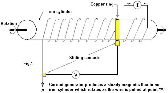
The flux is
changing as the coil is unwound by the rotation of the cylinder, as
illustrated. However, since B is static,
there is no variational e.m.f. and since the conductors are not modulating
lines of flux, there is no motional e.m.f.
Thus, dφ/dt in equation (11) is
zero, even though the flux is changing with time. Note that dφ/dt was defined as
representing the right hand part of the expression in equation (10) and
dφ/dt must not be interpreted more broadly than that.
In the application
of the present equations, it is required that all flux densities and movements
are referred to a single, specified co-ordinate system. In particular, the velocities will all be
with respect to this system alone and
not interpreted as relative velocities between conductors or moving lines of
flux. The co-ordinate system is selected
arbitrarily and the magnitudes of variational and motional fields depend upon
the selection.
Example 1:
A fundamental
electric generator is shown in Figure 2:
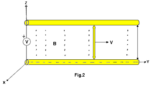
The parallel,
stationary conductors, separated by distance "l", have a stationary
voltmeter connected across them. The
circuit is completed by a moving conductor connected to the parallel conductors
by means of two sliding contacts. This
conductor is connected at y = 0 at time t = 0, and it moves to the right at a
constant velocity V = Vay. The applied
flux B is represented by dots on Fig.2 and has a magnitude of B = BO
CosBy Coswt ax. The unit vectors in the
direction of the co-ordinate axes are ax, ay and az respectively.
Solution: Let S denote the plane rectangular surface
bounded by the closed electric circuit, with a positive side selected as the
side facing you. The counter-clockwise
e.m.f. around the circuit is dφ/dt with φ signifying
the magnetic flux out of the positive side of S (As ds = 1 dy ax). The scalar product B x ds is BO l
CosBy, Coswt dy; integrating from y = 0 to y = y gives:
![]()
With y1
denoting the instantaneous y position of the moving wire. The counter-clockwise e.m.f. is found by
replacing y with vt and evaluating dφ/dt. The result is:
![]()
The variational
(transformer) component is determined
with the aid of equation (12) and is wBOl/BsinBy
sinwt where y = vt. This is the first
component on the right hand side of equation (13).
Note: y1
was treated as a constant when evaluating the partial time derivative of φ.
The motional E-field is the line integral of V x B along the path
of the moving conductor. As V x B is -BO
vcosBy1 coswt ax and As dl is dz ax, evaluation of the integral -BO
vcosBy1 coswt dz from Z = 0 to Z = 1 results in a motional E-field
of -BO lvcosBv1 coswt.
This component results from modulation of the lines of flux by the
moving conductor. If the voltmeter draws
no current, there can be no electromagnetic force on the free electrons of the
wire. Therefore, the e.m.f. along the
path of the metal conductors including the moving conductor, is zero.
Example 2:
Suppose the conductor with the sliding taps is stationary (V = 0)
and it is located at y = y1.
Also, suppose that the magnetic field B is produced by a system of
moving conductors which are not shown in Fig.2 and those conductors are
travelling with a constant velocity V = Vay.
At time t = 0, the magnetic field B is BO sinBy ax. Determine the voltage across the voltmeter.
Solution: There is no
motional E-field because the conductors in Fig.2 are at rest (stationary) with
respect to our selected co-ordinate system.
However, the magnetic field at points fixed with respect to the
co-ordinate system is changing with time and as a result, there is a
variational e.m.f. Since the B-field at
time t = 0 is BO sinBy ax and has a velocity of V = Vay, it can be
calculated that the B-field as a function of time is BOsin[B(y-vt)] ax. This is verified by noting that an observer
located at time t = 0 who is travelling at the constant velocity (V = Vay) of
the moving current, would have a y co-ordinate of y = y + Vt and an accordingly
different expression for B. He would
observe a constant field where the magnetic current density is:
![]()
The counter-clockwise e.m.f. can be arrived at by taking the
negative of an integral of the above expression for the rectangular surface
bounded by the electric circuit with the positive side facing you, with the
limits of zero and y. The resulting
e.m.f. equals:
![]()
which is the voltage across the meter.
Induced Motional Field - Negative Energy:
Conventional theory says that electric fields and magnetic fields
are different things. Consider for a
moment, a charge with an electric field around it. If the charge is moved, then a magnetic field
develops and the moving charge constitutes a current. If an observer were to move along with the
charge, then he would see no relative motion, no current and no magnetic field. A stationary observer would see motion,
current and a magnetic field. It would
appear that a magnetic field is an electric field observed from a motional
reference frame. Similarly, if we take a
mass with a gravity field around it, and we move the mass and create a mass
current, a new field is also created. It
is a different kind of gravity field with no source and no sink. It is called the "Protational
field" and is also known as the "Lense-Thirring Effect". This field and it's governing principles will
form the basis for future anti-gravitational devices (see figures 1 to 4).
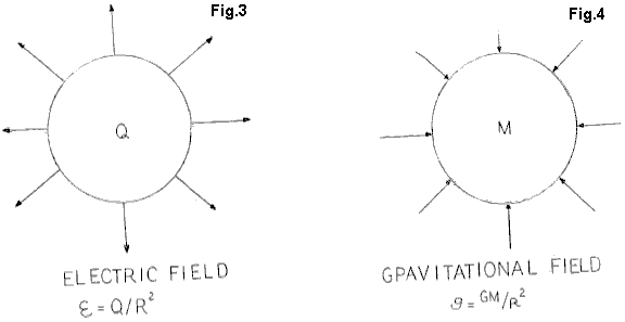
Within the confined are of the Vacuum Triode box, the space-time
continuum is reversed by the fields which are produced in the presence of
excited coherent space flux. These
quanta have been attracted from, and ultimately extracted from the virtual
vacuum, the infinitely non-exhaustible
With regards to over-unity phenomena, it is important to note that
so long as positive energy is present in a positively-flowing time regime, then
unity and over-unity power gains are not possible. The summation of the losses due to
resistance, impedance, friction, magnetic hysteresis, eddy currents and windage
losses of rotating machinery will always reduce overall efficiency below unity
for a closed system. The laws of
conservation of energy always apply to all systems. However, the induced motional E-field changes
the system upon which those laws need to be applied. Since the vacuum triode operates in more than
four dimensions and provides a link between the multi-dimensional reality of
the quantum state and the
To achieve unity, the summation of all magnetic and ohmic losses
must equal zero. To achieve this state,
negative energy and negative time need to be created. When this is achieved, all ohmic resistance
becomes zero and all energy then flows along the outside of conductors in the
form of a special space field. Negative
energy is fully capable of lighting incandescent lights, running motors and
performing all of the functions of positive energy tested to date. When run in parallel with positive energy
however, cancellation (annihilation) of opposing power types occurs. This has been fully tested in the laboratory.
Once unity has been achieved and the gate to the Dirac sea opened,
over-unity is affected by loading the open gate more and more, which opens it
further to the point where direct communication / interaction with the nucleus
of the atom itself is achieved. Output
of the vacuum triode is not proportional to the excitation input as the output
produced by the device is directly proportional to the load which is placed on
it. That load is the only dependent
variable for device output. The triode's
output voltage and frequency always remains constant due to the conditioning of
the motional E-field in the permanent magnets and the small regulated
excitation signal which is provided through a small oscillator. Regulation remains constant and the triode
output looks into an in-phase condition (cosθ=1 Kvar=1) under all load characteristics.
the vacuum triode is a solid-state device consisting of conditioned
permanent magnets capable of producing a motional field. This field opens the gate to the
The fundamental magnets have been broken free of the binding forces
which constrained them to be steady-state single-pole uniform magnetic flux
devices. They are now able to simply support
mass, as demonstrated with the transformer steel illustration. They can now easily be made to adopt a
dynamic motional field by applying a tiny amount of excitation. Specifically, 1 milliamp at 10 volts (10
milliwatts) of excitation at 60 Hz enables the coils of the triode to receive
from the Dirac Sea, more than 5,000 watts of usable negative energy. It has not yet been determined how much more
energy can be safely removed.
Theodore
Annis & Patrick Eberly
ENERGY GENERATION APPARATUS
AND METHODS
BASED UPON MAGNETIC FLUX
SWITCHING
ABSTRACT
Methods and apparatus generate electricity through the operation of a circuit based on a single magnetic flux path. A magnetisable member provides the flux path. One or more electrically conductive coils are wound around the member, and a reluctance or flux-switching apparatus is used to control the flux. When operated, the switching apparatus causes a reversal of the polarity (direction) of the magnetic flux of the permanent magnet through the member, thereby inducing alternating electrical current in each coil. The flux-switching apparatus may be motionless or rotational. In the motionless embodiments, two or four reluctance switches are operated so that the magnetic flux from one or more stationary permanent magnet(s) is reversed through the magnetisable member. In alternative embodiments, the flux-switching apparatus comprises a body composed of high-permeability and low-permeability materials, such that when the body is rotated, the flux from the magnet is sequentially reversed through the magnetisable member.
FIELD OF
THE INVENTION
The present invention relates to methods and apparatus wherein the magnetic flux from one or more permanent magnets is reversed repeatedly in polarity (direction) through a single flux path around which there is wound a conducting coil or coils for the purpose of inducing electricity in the coils.
BACKGROUND
OF THE INVENTION
The electromechanical and electromagnetic
methods involved in motional electric generators and alternators are well
known. Alternators and generators often employ permanent magnets and usually
have a rotor and a stator and a coil or coils in which an EMF (electromotive
force) is induced. The physics involved for producing electricity is described
by the generator equation V = ∫(vxB).dl.
Permanent magnets made of materials that
have a high coercively, a high magnetic flux density a high magnetic motive force
(mmf), and no significant deterioration of magnetic strength over time are now
common. Examples include ceramic ferrite magnets (Fe2O3); samarium cobalt
(SmCO5); combinations of iron, neodymium, and boron; and others.
Magnetic paths for transformers are often
constructed of laminated ferrous materials; inductors often employ ferrite
materials, which are used for higher frequency operation for both devices. High performance magnetic materials for use
as the magnetic paths within a magnetic circuit are now available and are well
suited for the (rapid) switching of magnetic flux with a minimum of eddy
currents. An example is the FINEMET®
nanocrystalline core material made by Hitachi of Japan.
According to Moskowitz, "Permanent
Magnet Design and Application Handbook" 1995, page 52, magnetic flux may
be thought of as flux lines which always leave and enter the surfaces of
ferromagnetic materials at right angles, which never can make true right-angle
turns, which travel only in straight or curved paths, which follow the
shortest distance, and which follow the path
of lowest reluctance.
A "reluctance switch" is a device
that can significantly increase or decrease (typically increase) the reluctance
(resistance to magnetic motive force) of a magnetic path in a direct and rapid
manner and subsequently restore it to its original (typically lower) value in a
direct and rapid manner. A reluctance
switch typically has analog characteristics.
By way of contrast, an off/on electric switch typically has a digital characteristic,
as there is no electricity "bleed-through." With the current state of
the art, reluctance switches have magnetic flux bleed-through. Reluctance
switches may be implemented mechanically, such as to cause keeper movement to
create an air gap, or electrically by several means, or by other means. One electrical means is that of using control
coils wound around the flux paths.
Another electrical means is the placement
within the flux path of certain classes of materials that change (typically increase)
their reluctance upon the application of electricity. Another electrical means is to saturate a
region of the switch material so that the reluctance increases to that of air
by inserting conducting electrical wires into the material as described by
Konrad and Brudny in "An Improved Method for Virtual Air Gap Length
Computation," in IEEE Transactions on Magnetics, Vol. 41, No. 10, October
2005.
The patent literature describes a number of
constructs that have been devised to vary the amounts of magnetic flux in
alternate flux paths by disproportionately dividing the flux from a stationary
permanent magnet or magnets between or among alternate flux paths repeatedly
for the purpose of generating electricity. The increase of flux in one magnetic
path and the corresponding decrease in the other path(s) provide the basis for
inducing electricity when coils are wound around the paths. The physics
involved for producing electricity by these constructs is described by the
transformer equation V = -∫dB/dt.ds. A variety of reluctance switching
means have been employed to cause the flux to be increased/decreased through a
particular alternate path with a corresponding decrease/increase in the other
path and to do so repeatedly.
A means of switching flux along alternate
paths between the opposite poles of a permanent magnet have included the flux
transfer principle described by R. J. Radus, Engineers' Digest, July, 1963.
A result of providing alternate flux paths
of generally similar geometry and permeability is that, under particular
conditions, the alternate path first selected or the path selected for the
majority of the flux will remain a "preferred path" in that it will
retain more flux and the other path, despite the paths having equal reluctance.
(There is not an automatic equalization of the flux among similar paths.)
Moskowitz, "Permanent Magnet Design and
Application Handbook" 1995, page 87 discusses this effect with regard to
the industrial use of permanent magnets to lift and release iron and steel by
turning the permanent magnet on and (almost) off via reluctance switching that
consists of the electric pulsing of coils wound around the magnetic flux paths
(the reluctance switches).
Experimental results with four iron
rectangular bars (relative permeability=1000) placed together in a square with
a bar permanent magnet (flux density measured at one pole=5000 Gauss) between
two of the opposing bars roughly in a centre position showed that removal and
replacement of the one of the end bars that is parallel to the
bar magnet will result in about 80% of the
flux remaining in the bar that remained in contact. The results further showed
that the preferred path must experience an increase of reluctance about IOx of
that of the available alternate path before its disproportionate flux condition
will yield and transfer to the alternate path.
Flynn
magnet or magnets between and among
alternate paths for the purpose of generating electricity (and/or motive
force). They provide for the increase of
magnetic flux in one path with a corresponding decrease in the other path(s).
There are always at least two paths.
SUMMARY
OF THE INVENTION
The present invention relates to methods and
apparatus for the production of electricity through the operation of a circuit
based upon a single magnetic flux path. A magnetisable member provides the flux
path. One or more electrically conductive coils are wound around the member,
and a reluctance or flux switching apparatus is used to control the flux. When
operated, the switching apparatus causes a reversal of the polarity (direction)
of the magnetic flux of the permanent magnet through the member, thereby
inducing alternating electrical current in each coil.
According to the invention, the flux
switching apparatus may be motionless or rotational. In the motionless
embodiments, four reluctance switches are operated by a control unit that
causes a first pair of switches to open (increasing reluctance), while another
pair of switches close (decreasing reluctance). The initial pair is then closed
as the other pair is opened, and so on. This 2x2 opening and closing cycle
repeats and, as it does, the magnetic flux from the stationary permanent
magnet(s) is reversed in polarity through the magnetisable member, causing
electricity to be generated in the conducting coils. An alternative motionless
embodiment uses two reluctance switches and two gaps of air or other materials.
In alternative embodiments, the flux
switching apparatus comprises a body composed of high-permeability and
low-permeability materials, such that when the body is rotated, the flux from
the magnet is sequentially reversed through the magnetisable member. In the
preferred embodiment the body is cylindrical having a central axis, and the
body rotates about the axis. The cylinder is composed of a high-permeability
material except for section of low-permeability material that divided the
cylinder into two half cylinders. At least one electrically conductive coil is
wound around the magnetisable member, such that when the body rotates an
electrical current is induced in the coil. The body may be rotated by
mechanical, electromechanical or other forces.
A method of generating electrical current,
comprises the steps of providing a magnetisable member with an electrically
conductive coil wound therearound, and sequentially reversing the flux from a
permanent magnet through the member, thereby inducing electrical current in the
coil.
BRIEF DESCRIPTION OF THE DRAWINGS
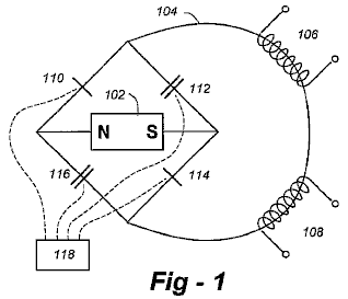
Fig.1 is a schematic diagram of a magnetic
circuit according to the invention.
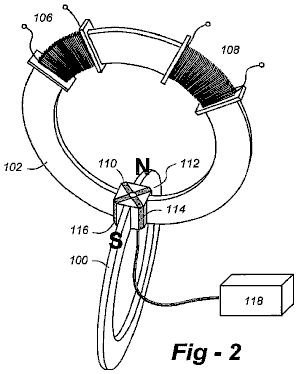
Fig.2 is a perspective view of an embodiment
of the invention based upon motionless magnetic flux switches.
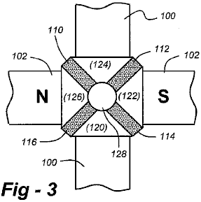
Fig.3 is a detail drawing of a motionless
flux switch according to the invention.
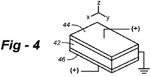
Fig.4 is a detail drawing of a reluctance
switch according to the invention.
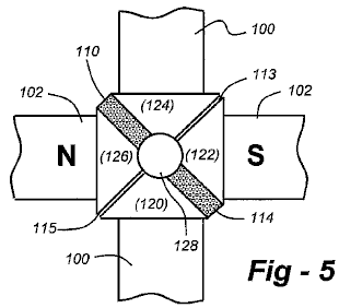
Fig.5 is a detail drawing of an alternative
motionless flux switch according to the invention which utilizes gaps of air or
other materials.
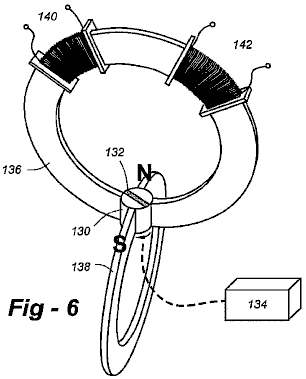
Fig.6 is a schematic diagram of a system
using a rotary flux switch according to the invention.
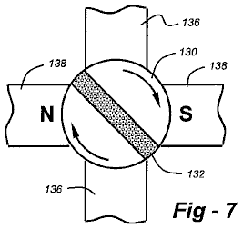
Fig.7 is a detail drawing of a rotary flux
switch according to the invention.
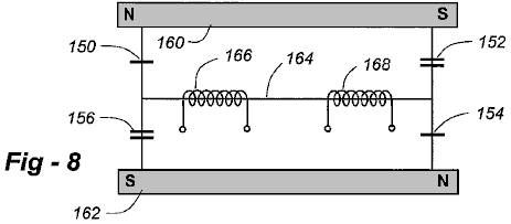
Fig.8 is a schematic diagram of a circuit
according to the invention utilizing two permanent magnets and a single flux
path.
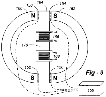
Fig.9 shows one possible physical embodiment
of the apparatus with the components of FIG. 8, including a reluctance switch
control unit.
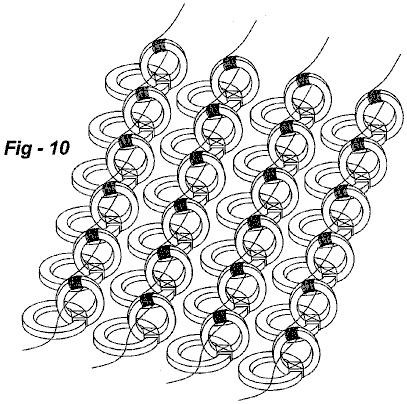
Fig.10 shows and array of interconnected
electrical generators according to the invention.
DETAILED DESCRIPTION OF THE PREFERRED EMBODIMENTS
Fig.1 is a schematic diagram of a magnetic
circuit according to the invention utilizing a motionless flux switch. The circuit includes the following
components: a permanent magnet 102, single flux path 104, conducting coils 106,
108, and four reluctance switches 110, 112, 114, 116. Under the control of unit 118, reluctance
switches 110, 114 open (increasing reluctance), while switches 112, 116 close
(decreasing reluctance). Reluctance
switches 110, 114 then close, while switches 112, 116 open, and so on. This 2x2 opening and closing cycle repeats
and, as it does, the magnetic flux from stationary permanent magnet 102 is
reversed in polarity through single flux path 104, causing electricity to be
generated in conducting coils 106, 108.
An efficient shape of permanent magnet 102
is a "C" in which the poles are in close proximity to one another and
engage with the flux switch. The single
flux is carried by a magnetisable member 100, also in a "C" shape
with ends that are in close proximity to one another and also engage with the
flux switch. In this, and in other
embodiments, the 2x2 switching cycle is carried out simultaneously. As such, control circuit 118 is preferably
implemented with a crystal-controlled clock feeding digital counters, flip-flops,
gate packages, or the like, to adjust rise time, fall time, ringing and other
parasitic effects. The output stage of
the control circuit may use FET (Field-Effect Transistor switches) to route
analog or digital waveforms to the reluctance switches as required.
Fig.2 is a perspective of one possible
physical embodiment of the apparatus using the components of Fig.1, showing
their relative positions to one another.
Reluctance switches 110, 112, 114, 116 may be implemented differently,
as described below, but will usually occupy the same relative position within
the apparatus.
Fig.3 is a detail drawing of the motionless
flux switch. Connecting segments 120, 122, 124, 126 must be made of a
high-permeability ferromagnetic material.
The central volume 128 may be a through-hole, providing an air gap, or
it may be filled with glass, ceramic or other low-permeability material. A super-conductor or other structure
exhibiting the Meissner effect may alternatively be used.
In the embodiment depicted in Fig.2 and
Fig.3, reluctance switches 110, 112, 114, 116 are implemented with a
solid-state structure facilitating motionless operation. The currently
preferred motionless reluctance switch is described by Toshiyuki Ueno &
Toshiro Higuchi, in the paper "Investigation on Dynamic Properties of
Magnetic Flux Control Device composed of Lamination of Magnetostrictive
Material Piezoelectric Material," The University of Tokyo 2004, the
entirety of which is incorporated herein by reference. As shown in Fig.4, this switch is made of a
laminate of a GMM (Giant Magnetostrictive Material 42), a TbDyFe alloy, bonded
on both sides by a PZT (Piezoelectric) material 44, 46 to which electricity is
applied. The application of electricity
to the PZT creates strain on the GMM, which causes its reluctance to increase.
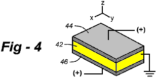
Other arrangements are applicable, including
those disclosed in pending U.S. Patent Application Serial no. 2006/0012453, the
entire content of which is incorporated herein by reference. These switches disclosed in this reference
are based upon the magnetoelectric (ME) effects of liquid crystal materials in
the form of magnetorestrictive and piezoelectric effects. The properties of ME materials are described,
for example, in Ryu et al, "Magnetoelectric Effect in Composites of
Magnetorestrictive and Piezoelectric Materials," Journal of
Electroceramics, Vol. 8, 107-119
Filipov et al, "Magnetoelectric Effects
at Piezoresonance in Ferromagnetic-Ferroelectric Layered Composites,"
Abstract, American Physical Society Meeting (March 2003) and Chang et al.,
"Magneto-band of Stacked Nanographite Ribbons," Abstract, American
Physical Society Meeting (March 2003). The entire content of each of these
papers are also incorporated herein.
Further alternatives include materials that
may sequentially heated and allowed to cool (or cooled and allowed to warm up
or actively heated and cooled) above and below the Currie temperature, thereby
modulating reluctance. Gadolinium is a candidate since its Currie point is near
room temperature. High-temperature superconductors are other candidates, with
the material being cooled in an insulated chamber at a temperature
substantially at or near the Currie point.
Microwave or other energy sources may be used in conjunction with the
control unit to effectuate this switching.
Depending upon how rigidly the switches are contained, further
expansion-limiting `yokes' may or may not be necessary around the block best
seen in Fig.4.
Fig.5 is a detail drawing of an alternative
motionless flux switch according to the invention which utilizes gaps of air or
other materials. This embodiment uses
two electrically operated reluctance switches 110, 114, and two gaps 113, 115,
such that when the switches are activated in a prescribed manner, the flux from
the magnet 102 is blocked along the switch segments containing the switches and
forced through the gap-containing segments, thereby reversing the flux through
the magnetisable member 100. Upon
activation of the two reluctance switches 110, 114, the flux, seeking a path of
significantly lower reluctance, flips back to the original path containing the
(non deactivated) reluctance switches, thereby reversing the flux through the
member 100. Note that the flux switches may also be electromagnetic to saturate
local regions of the switch such that reluctance increases to that of air (or
gap material), creating a virtual gap as described by Konrad and Brudny in the
Background of the Invention.
More particularly, flux switching apparatus
according to this embodiment uses a permanent magnet having a north pole `N'
and a south pole `S' in opposing relation across a gap defining a volume. A magnetisable member with ends `A' and 'B'
is supported in opposing relation across a gap sharing the volume, and a flux
switch comprises a stationary block in the volume having four sides, 1-4, with
two opposing sides interfaced to N and S, respectively and with the other two
opposing sides being interfaced to A and B, respectively. The block is composed of a magnetisable
material segmented by two electrically operated magnetic flux switches and two
gaps filled with air or other material(s).
A control unit in electrical communication with the flux switches is
operative to:
a) passively allow a default flux path
through sides 1-2 and 3-4, then
b) actively establish a flux path through
sides 2-3 and 1-4, and
c) repeat a) and b) on a sequential basis.
As an alternative to a motionless flux
switch, a rotary flux switch may be used to implement the 2x2 alternating sequence. Referring to Fig.6 and Fig.7, cylinder 130
with flux gap 132 is rotated by a motive means 134. This causes the halves of
cylinder 130 to provide two concurrent and separate magnetic flux bridges
(i.e., a "closed" reluctance switch condition), in which a given end
of magnetisable member 136 is paired up with one of the poles of stationary
permanent magnet 138. Simultaneously,
the other end of single flux path carrier 136 is paired up with the opposite
pole of stationary permanent magnet 138.
Fig.7 is a detail view of the cylinder. Each 90° rotation of the cylinder causes the
first flux bridges to be broken (an "open" reluctance switches
condition) and a second set of flux bridges to be created in which the given
end of member 136 is then bridged with the opposite pole of stationary
permanent magnet 138. A full rotation
of cylinder 130 causes four such reversals.
Each flux reversal within single flux path 2 causes an electric current
to be induced in conducting coil(s) 140, 142.
In this embodiment, it is important to keep a precise, consistent
spacing between each of the "halves" of (rotating) cylinder 130 in
relation to the poles of permanent magnet 138 and the ends of flux path carrier
136 as the magnetic flux bridges are provided by the cylinder 130 as it
rotates.
Rotating cylinder 130 is made of high
magnetic permeability material which is divided completely by the flux gap
132. A preferred material is a
nanocrystalline material such as FINEMET® made by
An efficient shape of magnetisable member
136 is a "C" in which its opposing ends are curved with a same radius
as cylinder 130 and are in the closest possible proximity with rotating
cylinder 130. Permanent magnet 138 is
also preferably C-shaped in which the opposing poles are curved with a same
radius as cylinder 130 and are in the closest possible proximity with rotating
cylinder 130. Manufacturing and assembly
considerations may dictate other shapes.
While the embodiments described thus far
utilize a single permanent magnet, other embodiments are possible according to
the invention utilizing a plurality of permanent magnets while nonetheless
generating a single flux path. Fig.8
depicts a circuit utilizing two permanent magnets and a single flux path. Fig.9 shows one possible physical embodiment
of the apparatus based upon the components of Fig.8, including a reluctance
switch control unit 158.
Under the control of unit 158, reluctance
switches 150, 152 open (increasing reluctance), while switches 154, 156 close
(decreasing reluctance). Reluctance
switches 150, 152 then close, while switches 154, 156 open, and so on. This 2x2
opening and closing cycle repeats and, as it does, the magnetic flux from
stationary permanent magnets 160, 162 is reversed in polarity through the
magnetisable member, causing electricity to be generated in conducting coils
166, 168.
In the preferred implementation of this
embodiment, the magnets are arranged with their N and S poles reversed. The
magnetisable member is disposed between the two magnets, and there are four
flux switches, SW1-SW4, two between each end of the member and the poles of
each magnet. The reluctance switches are implemented with the structures
described above with reference to Figs. 1 to 3.
For added particularity, assume the first
magnet has north and south poles, N1 and S1, the second magnet has north and
south poles, N2 and S2 and the member has two ends A and B. Assuming SW1 is
situated between N1 and A, SW2 is between A and S2, SW3 is between N2 and B,
and SW4 is between B and S1, the control circuitry operative to activate SW1
and SW4, then activate SW2 and SW3, and repeat this process on a sequential
basis. As with the other embodiments described herein, for reasons of
efficiency, the switching is carried out simultaneously.
In all of the embodiments described herein
the material used for the permanent magnet(s) may be either a magnetic assembly
or a single magnetized unit. Preferred
materials are ceramic ferrite magnets (Fe203), samarium
cobalt (SmCO5), or combinations of iron, neodymium, and boron. The single flux path is carried by a material
having a high magnetic permeability and constructed to minimize eddy
currents. Such material may be a
laminated iron or steel assembly or ferrite core such as used in transformers.
A preferred material is a nanocrystalline material such as FINEMET®. The conducting coil or coils are wound around
the material carrying the single flux path as many turns as required to meet
the voltage, current or power objectives. Ordinary, standard, insulated, copper
magnet wire (motor wire) is sufficient and acceptable. Superconducting materials may also be
used. At least some of the electricity
induced in the conducting coils may be fed back into the switch control unit. In this mode of operation, starting pulses of
electricity may be provided from a chemical or solar battery, as required.
Although in the embodiments of Fig.2 and
Fig.6 the magnet and flux-carrying materials are flat elements lying in
orthogonal planes with flux-carrying material lying outside the volume
described by the magnet, the flux path may be disposed `within' the magnet
volume or configured at an angle. The
physical scale of the elements may also be varied to take advantage of
manufacturing techniques or other advantages.
Fig.10, for example, shows an array of magnetic circuits, each having
one or more coils that may be in series, parallel, or series-parallel
combinations, depending upon voltage or current requirements. In each case the magnets may be placed or
fabricated using techniques common to the microelectronics industry. If mechanical flux switches are used they may
be fabricated using MEMs-type techniques.
If motionless switches are used, the materials may be placed and/or
deposited. The paths are preferably
wound in advance then picked and placed into position as shown. The embodiment shown in Fig.9 is also
amenable to miniaturization and replication.
The Energy
Conversion Device of William McDavid junior
US
Patent 6,800,955 5th Oct.
2004 Inventor: William
McDavid jnr.
Fluid-powered energy
conversion device
Note: The wording of this
patent has been altered to make it easier to understand. An unaltered copy can be downloaded from www.freepatentsonline.com. In this patent, William relates sections of
his design according to the direction of flow through the housing and so he
calls the first section the “downstream” chamber and the following chamber as
the “upstream” chamber. Although water
could be used, this patent essentially describes a high-efficiency wind-powered
generator. For dimensions: one inch =
25.4 mm.
Abstract:
A fluid-powered energy conversion device
which converts energy in a moving fluid into mechanical energy. A rigid cylindrical frame of toroidal baffles
forms an “upstream” annular or ring-shaped chamber and a “downstream” annular
chamber, each of the chambers having open sides to allow the entry of the
fluid. The toroidal baffles create an upstream drive vortex in an upstream central vortex chamber, and a downstream
extraction vortex rotating in the
opposite direction in a downstream central vortex chamber. A set of hinged
louvers surround the vortex chambers and these allow the fluid to enter each
chamber only in the direction of vortex rotation, and prevent the fluid from
exiting through the sides of the device. The driving vortex passes through, and
rotates, a turbine positioned in a central aperture between the two chambers.
The turbine blades are rotated by the rotational momentum of the driving fluid
vortex, plus the lift generated by each turbine blade, plus the additional
momentum imparted by the vortex reversal.
McDavid, Jr. – US 6,710,469
McDavid, Jr. – US 6,518,680
Walters –
Description:
BACKGROUND OF THE INVENTION
1. Technical Field of the Invention
The present invention relates
generally to electrical generation and energy conversion devices, and more
particularly to a fluid-powered energy conversion device which converts the
energy of wind or flowing water into mechanical or electrical energy.
2. Description of Related Art
The use of wind or flowing water to
provide power for various uses dates back many centuries. In modern times, wind and water have been
used to generate electricity. Hydroelectric
generating plants have been used to generate large quantities of electrical
energy for widespread distribution.
However, this requires major permanent environmental changes to the
areas where dams are built and reservoirs rise.
Wind-powered devices, in general, have been used to perform mechanical
work, or to generate electricity, only on a limited scale. With the ever increasing demand for
additional, or alternative energy sources, all possible sources are being given
more scrutiny. This is particularly true
for sources which are non-polluting and inexhaustible. Free-flowing
hydro-electric and wind-powered systems provide such sources, and the capturing
of increased energy from wind and water has received much consideration.
However, commercial hydro-electric and
wind-powered electrical generation devices which are currently in use have
several disadvantages. Wind-powered
devices, in particular, are expensive, inefficient, dangerous, noisy, and
unpleasant to be around. To capture a
large volume of wind, existing wind-powered devices are very large. As a
result, they cannot be distributed throughout population centres, but must be
installed some distance away. Then, like dams with hydro-electric generators,
the electrical energy they generate must be transmitted, at considerable cost
and with considerable energy loss, to the population centres where the energy
is needed.
It would be desirable to distribute
smaller water-powered and wind-powered units throughout the population centres.
For example, it would be desirable to have a wind-powered unit for each
building structure, thus distributing the generating capacity over the entire
area, and making the energy supply less vulnerable to local events such as
storms or earthquakes. Such distributed
generation would also solve the most common and valid objection to wind power,
namely, that the wind does not blow all the time. In a large geographical area, however, wind
is almost always blowing somewhere.
Therefore, with wind-powered generators which are distributed throughout
the area, power could be generated in the areas where the wind is blowing, and
then transmitted to the rest of the power grid. However, with existing
technology, smaller units suitable for distributing throughout a population
area are not efficient enough to provide a sufficient amount of energy to power
a structure such as a house or office building.
In addition, such units are visually obtrusive and noisy, making them
unsuitable for use in residential or other highly populated settings.
Existing wind-powered electrical
generation devices commonly utilise a propeller mounted on the horizontal shaft
of a generator which, in turn, is mounted at the top of a tower. This is an inefficient design because energy
is extracted from the wind by reducing the wind velocity as it passes through
the propeller. This creates a pocket of
slow-moving air cantered behind the propeller, which the ambient wind blows
around. Therefore, only the outer
portion of the propeller blades use the wind efficiently.
To counter this effect, modern
windmill designs utilise extremely long propeller blades. The use of such
massive blades, however, has its own disadvantages. Firstly, the propellers are known to kill or
injure thousands of large birds each year.
Secondly, the massive blades can be dangerous if the device fails
structurally and the propeller breaks loose.
In this case, the propeller can fly a considerable distance and cause
serious damage or injury to anything or anyone in its path. Thirdly, the propeller design contains an
inherent gravitational imbalance. The
rising blades on one side of the propeller's hub are opposing gravity, while
the descending blades on the other side of the hub are falling with gravity. This imbalance creates a great deal of vibration
and stress on the device. Consequently, the device must be structurally
enhanced, at great expense, to withstand the vibration and stress, and thus
avoid frequent maintenance and/or replacement.
It would therefore be advantageous
to have a fluid-powered energy conversion device which overcomes the
shortcomings of existing devices. Such a
device could utilise wind energy or the energy of flowing water to provide
mechanical energy or electrical energy.
The present invention provides such a device.
SUMMARY OF THE INVENTION
One aspect, the present invention is
a fluid-powered energy-conversion device for converting energy in a moving
fluid into mechanical energy. The device
includes a rigid cylindrical frame which has an “upstream” annular (ring-shaped)
chamber and a “downstream” annular chamber.
Each of the chambers has sides which are open to allow entry of the
moving fluid. A first set of baffles are mounted longitudinally in the upstream
chamber, and these create a driving vortex which rotates in a first direction
when the moving fluid enters the upstream chamber through the upstream
chamber's open sides. A set of hinged
louvers are positioned in the openings between these baffles, creating a
central vortex chamber centered on the longitudinal axis of the device.
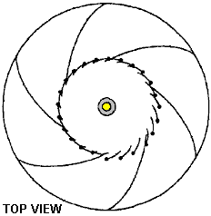
This first set of louvers permits
entry of the moving fluid into the upstream central vortex chamber only when
the fluid is rotating in the first direction.
They also prevent the fluid from exiting from the upstream central vortex
chamber through the sides of the device.
The device also includes a floor of the upstream annular chamber which
slopes upwards towards the downstream chamber as the floor approaches the
central longitudinal axis of the device.
This sloping floor causes the drive
vortex to flow “downstream” (upwards for air) through the upstream central
vortex chamber and pass through a central aperture located between the upstream
annular chamber and the downstream annular chamber. A longitudinal drive shaft is mounted
centrally in the central aperture, and a turbine is mounted on the drive shaft
in the central aperture. The turbine is rotated by the drive vortex as the
drive vortex passes through the central aperture.
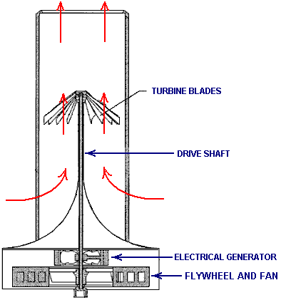
The device may also include a second
set of baffles longitudinally mounted in the “downstream” (upper for air)
chamber which operate to create an extraction vortex which rotates in the
opposite direction when the moving fluid enters the downstream chamber through
the downstream chamber's open sides.
Additionally, a second set of hinged louvers may be positioned in the
openings between the second set of baffles, encircling a downstream central
vortex chamber. The second set of
louvers permit entry of the moving fluid into the downstream central vortex
chamber only when the fluid is rotating in the direction opposite to the
direction of flow in the “upstream” camber. These louvers also prevent the
fluid from exiting the downstream central vortex chamber through the sides of
the device. In this manner, the turbine
is rotated by the drive vortex as the drive vortex passes through the turbine
and reverses direction to match the direction of the extraction vortex.
For high-wind conditions or when
powered by water flow, the driving vortex and extraction vortex may rotate in
the same direction. The first set of
hinged louvers form the upstream central vortex chamber, and the second set of
hinged louvers form the downstream central vortex chamber. The first set of louvers permit entry of the
wind or water into the upstream central vortex chamber only when the fluid is
rotating in the first direction.
BRIEF DESCRIPTION OF THE DRAWINGS
The invention will be better
understood and its numerous objects and advantages will become more apparent to
those skilled in the art by reference to the following drawings, in conjunction
with the accompanying specification, in which:
FIG.1 is a perspective view of
a first embodiment of the present invention that converts wind energy to
mechanical or electrical energy;
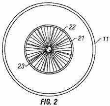
FIG.2 is a top plan view of
the embodiment of Fig.1
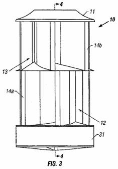
FIG.3 is a side elevational
view of the embodiment of Fig.1
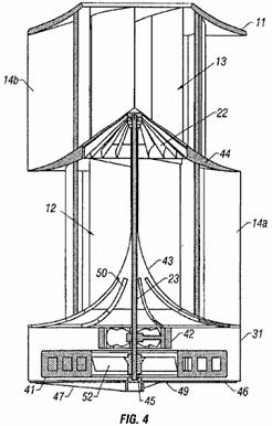
FIG.4 is a cross-sectional
view of the embodiment of Fig.1 taken along line 4 — 4 of Fig.3
with an electrical generator installed to produce electrical energy;

FIG.5 is a perspective view of
a fluid-filled flywheel suitable for use with the present invention;
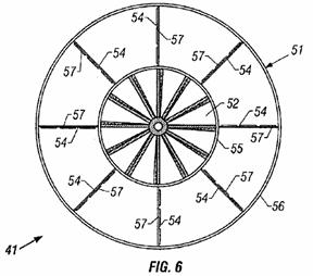
FIG.6 is a top plan view of
the fluid-filled flywheel of Fig.5

FIG.7 is a cross-sectional
view of an embodiment of the present invention that converts the energy of
flowing water to electrical energy;
FIG.8 is a perspective view of
the embodiment of Fig.1 with the longitudinal baffles drawn in phantom so that
the annular central divider (mid-deck) and turbine can be seen
FIG.9 is a horizontal
cross-sectional view of the embodiment of Fig.1 taken along line 9 — 9
of Fig.8
FIG.10 is a perspective view of
a second embodiment of the present invention that converts wind energy to
mechanical or electrical energy, with the longitudinal baffles drawn in phantom
so that a set of hinged longitudinal louvers can be seen; and
FIG.11 is a horizontal
cross-sectional view of the embodiment of Fig.10 taken along line 11 — 11
.
In the drawings, like or similar
elements are designated with identical reference numerals throughout the
various views, and the various elements shown are not necessarily drawn to
scale.
DETAILED DESCRIPTION OF EMBODIMENTS
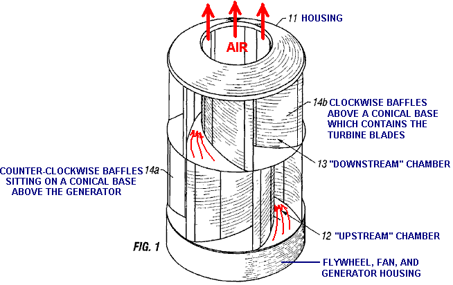
Fig.1 is a perspective view of
an embodiment of the present invention which converts wind energy to mechanical
or electrical energy. The energy
conversion device 10 includes a stationary cowling 11 surrounding
an upstream (lower) ring-shaped or doughnut-shaped chamber 12 and a
downstream (upper) ring-shaped chamber 13. The cowling may be
constructed of any suitable rigid material such as wood, plastic, metal, or
similar. The cowling may be constructed
from a transparent material, making the device visually unobtrusive. In the preferred
embodiment of the present invention, the cowling is cylindrical and is
constructed of a high-grade, ultraviolet-protected plastic.
The cowling 11 includes a set
of longitudinal baffles which are curved and arranged in a toroidal pattern.
Upstream baffles 14a are mounted in the
upstream annular chamber 12, and downstream baffles 14b
are mounted in the downstream annular chamber 13. In the preferred embodiment of the present
invention, approximately six toroidal longitudinal baffles are mounted in each
chamber. The baffles function to guide
the wind into each chamber. The
narrowing cross-sectional area between the baffles causes the air to accelerate
as it moves toward the centre of the device, creating two high-velocity
vortices (an upstream drive vortex and a downstream extraction vortex). Although the invention is described here
primarily as a vertically-oriented cylinder, it should be understood that the
device may be installed in other positions, such as a horizontal orientation, which
results in the device having an upstream annular chamber and a downstream
annular chamber which are at the same height.
Alternatively, as noted below in connection with Fig.7, the device may be inverted when used in water since water
vortices move more readily downwards rather than upwards.
In the embodiment illustrated in Fig.1, in which low-speed wind is the
input energy source, the upstream baffles 14a and the downstream
baffles 14b are curved in opposite directions. The baffles therefore create two
high-velocity vortices which rotate in opposite directions. As described below in connection with Fig.4 , the direction of the vortex
flow is reversed in a turbine located between the upstream annular chamber 12
and the downstream annular chamber 13, thereby adding additional
rotational power to the turbine. In the
hydro-electrical embodiment in which flowing water is the input energy source,
and in high-speed wind conditions such as when the device is mounted on a
vehicle, the upstream baffles and the downstream baffles may be curved in the
same direction. In those particular
embodiments, therefore, the baffles create two high-velocity vortices which
rotate in the same direction. The device
may be converted from a low-wind device to a high-wind device by removing the
counter-rotational downstream annular chamber 13 and replacing it with a
downstream annular chamber which creates a vortex rotating in the same
direction as the drive vortex.
In the preferred embodiment of the
present invention, plastic mesh (not shown) may surround the entry and exit
openings of the cowling 11 to prevent birds, animals, or debris from
entering the device 10. In addition, should the device fail
structurally, any broken parts are contained by the mesh instead of flying out
into the vicinity and causing damage or injury.
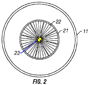
Fig.2 is a top plan view of
the embodiment of Fig.1.
The top of the cowling 11 includes a central aperture 21 through
which the air in the extraction vortex exits the device. In the preferred embodiment, the extraction
vortex exits the device rotating in a counter-cyclonic direction (clockwise in
the Northern Hemisphere) so that it dissipates rather than creating potentially
damaging whirlwinds. The turbine 22 is
visible through the aperture. The turbine rotates around a central drive shaft 23
.
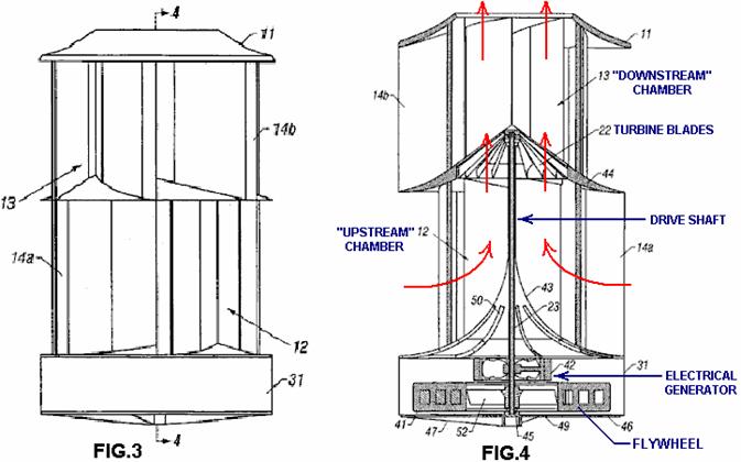
Fig.3 is a side-elevational
view of the embodiment of Fig.1
illustrating the profile of the cowling 11, the upstream annular chamber
12, the downstream annular chamber 13, and the baffles 14a
and 14b. The cowling may be
mounted on a base 31 and the base 31
may also be used to enclose additional mechanical assemblies such as a flywheel
and/or an electrical generator.
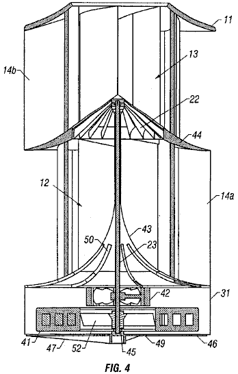
Fig.4 is a cross-sectional
view of the embodiment of Fig.1
taken along line 4 — 4 of Fig.3
with a flywheel 41 installed in the base 31 along with an
electrical generator 42 to produce electricity. Ambient wind flows simultaneously into the
upstream annular chamber 12 through upstream baffles 14a, and
into the downstream annular chamber 13 through the downstream baffles 14b
through the sides of the cowling 11.
The baffles guide the ambient wind towards the centre of the device 10. A sloping parabolic floor (deck) 43 of
the upstream annular chamber 12 causes the wind to flow downstream into
the centrally mounted turbine 22 that rotates on the central drive shaft
23. The device 10 produces
power by guiding ambient wind flows into two high-velocity vortices arranged
upstream and downstream of the turbine which converts the wind flows to
mechanical energy by turning the drive shaft 23. High-RPM and high-torque are produced by the
turbine due to three primary factors:
(1) each blade of the turbine is
shaped like a scoop which captures the rotational momentum of the drive vortex;
(2) each blade of the turbine has a
cross-sectional shape of an airfoil that generates lift in the direction of
rotation of the turbine; and
(3) in low wind
conditions, the reversal of the direction of the vortex rotation adds
additional force to the turbine in the direction of rotation.
The large flywheel 41 may be
attached to the rotating turbine drive shaft 23. In one embodiment, the flywheel may be a
permanent magnet, surrounded by copper windings. The flywheel may serve both as
an internal energy storage device due to its angular momentum, and as a dynamo
for the generator 42 mounted under the deck 43 of the upstream
annular chamber 12. A solid-state
electronic regulator (not shown) may be utilised to control the electrical
current load. The regulator maintains a
zero load until a preset rotational velocity (RPM) is reached. The load is then
increased in order to generate electricity while maintaining the RPM of the
turbine at a preselected level.
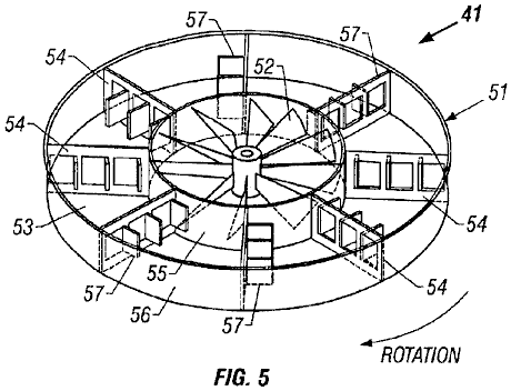
In Fig.5 is shown a perspective
view of another embodiment of the flywheel 41. In this embodiment, the flywheel (shown in
phantom) includes a hollow disk-shaped shell 51 which is filled with a
fluid such as water. The design shown
also includes a cooling fan 52 in the hub of the flywheel which rotates
with the drive shaft 23 and the flywheel to produce a flow of cooling
air that is used to cool the adjacent generator 42 (Fig.4 and Fig.7). The placement of the fan in the hub of the
flywheel creates an annular chamber 53 whicht holds the fluid. Within the chamber, there is a set of radial
bulkheads 54 extending from the interior wall 55 to the exterior
wall 56 of the chamber. Each of
the radial bulkheads includes hinged gates or hatches 57. In the example version shown here, each
radial bulkhead has three hinged gates.
During acceleration of the flywheel 41
, these gates 57 open in the opposite direction of rotation. This allows the fluid to flow through the
radial bulkheads 54, reducing start-up inertia. The fluid then slowly comes up to speed due
to friction with the interior and exterior walls 55 and 56 of the
annular chamber, and due to the motion of the radial bulkheads through the
fluid. During deceleration of the
flywheel, the gates close because of the forward momentum of the fluid. This
creates solid radial bulkheads and causes the flywheel to perform as a solid
flywheel. The angular momentum of the flywheel then helps to maintain the
angular velocity of the drive shaft 23 when the input power of the wind
drops off.
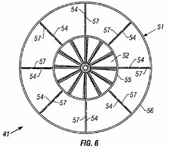
Fig.6 is a top plan view of
the fluid-filled flywheel 41 of Fig.5
, showing the blades of the cooling fan 52 in the hub of the flywheel,
the annular chamber 53, the radial bulkheads 54, and the gates 57
in the closed (decelerating) position.
Thus, the fluid-filled flywheel 41
is particularly well suited for use with this energy conversion device 10
of the present invention. The
fluid-filled flywheel allows rapid spin-up of the drive shaft 23 by
reducing the start-up inertia, but resists deceleration like a solid
flywheel. These features can
significantly boost the efficiency of a wind-powered or water-powered device
that operates with varying input power levels.
By simply inverting the flywheel, the fluid-filled flywheel can be used
with systems that spin either clockwise or counter-clockwise. As an additional
feature, shipping weight is greatly reduced because the fluid can be added at
the point of use.

Referring again to Fig.4 , an annular central divider
(mid-deck) 44 divides the upstream annular chamber 12 from the
downstream annular chamber 13.
The top of the mid-deck slopes away from the turbine, causing the
ambient wind entering the downstream annular chamber to flow away from the
turbine. This creates an area of reduced
air pressure on the downstream side of the turbine 22 that increases the
flow of air from the upstream annular chamber 12 through the
turbine. Each blade of the turbine 22
is a curved airfoil which receives rotational impetus from the rotation of
the drive vortex, the reversal of the vortex direction, and aerodynamic lift
that is generated by the airfoil in the direction of rotation of the turbine.
In the preferred embodiment of the
present invention, the turbine 22 and flywheel 41 may be made of
metal. Further, all metal parts may be coated with, for example, plastic,
chrome, or paint to prevent corrosion.
As discussed above, the flywheel may be a permanent magnet or may be a
fluid-filled flywheel. All bearings
such as bearing 45 may be magnetic-repulsion-levitation bearings so that
there is no physical contact between the moving and stationary elements of the
device. The base 31 may be
mounted on a support plate 46 and/or a support brace 47,
depending on the structure on which the device is mounted and the orientation
of the device.
The central drive shaft 23 may
also drive the cooling fan 52 that draws cooling air through vents 49
in the support plate and directs the air through the generator 42. The heated air may exit through louvers 50
in the parabolic deck 43 of the upstream annular chamber 12 where
it then mixes with the driving airflow in the upstream annular chamber to
defrost the interior of the device and the turbine 22.
The device 10 may vary in its
dimensions, depending upon the specific application for which it is
utilised. For example, the dimensions of
a wind-powered device that is mounted on the roof of a house may be between 40
inches and 48 inches in diameter, and between 60 inches and 78 inches in
height. In this configuration, the turbine 22 has a diameter
approximately one-half the diameter of the exterior of the cowling 11 (i.e. approximately 20 to 24 inches in
diameter). Larger versions may be
utilised for larger buildings such as factories or office buildings with
increased economies of scale. For
example, an office building may use a device that is 20 feet in diameter and 20
feet tall with a turbine that is 10 feet in diameter. A vehicle-mounted device (for example, for a
passenger car), designed for high-wind conditions, may be about 24 inches in
diameter and 6 inches in height. The generator and flywheel, if any, may be
mounted inside the contour of the vehicle, or on a luggage rack. A small
hydro-electric version of the device that is placed in a running stream or
river may have similar dimensions to the vehicle-mounted device. In addition,
since the outflow of the hydro-electric version is directed downward, a
deflector may be utilised in shallow bodies of water to prevent erosion of the
stream bed.
It should be noted that when the
present invention is oriented vertically, the turbine 22, the generator 42,
and the flywheel 41 rotate around a vertical axis. Therefore, the supporting structures are not
subject to the vibration and stress produced by gravity effects in prior art
devices in which propellers rotate around a horizontal axis. Moreover, exceptional
wind-conversion efficiency is realized from the present invention as it diverts
and accelerates the ambient wind flow into vortices that have several times the
velocity of the ambient wind flow when they reach the turbine. Additionally, the acceleration of the air
flow into the upstream and downstream annular chambers creates a low pressure
area that pulls air into the device from an effective cross-sectional area that
is greater than the physical cross-sectional area of the device. As a result, the
present invention provides a new and improved wind-power conversion device
which is quieter, safer, more efficient, and more cost effective than existing
devices.
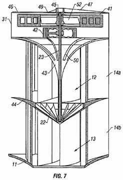
Referring now to Fig.7, there is shown a cross-sectional
view of a version of the present invention which converts the energy of flowing
water to electrical energy (i.e. a hydro-electrical device). There are three key differences between the
hydro-electrical embodiment from the low-wind-powered embodiment of Figs. 1 to 4. Firstly, the upstream baffles 14a and
the downstream baffles 14b curve in the same direction. The baffles therefore create two
high-velocity vortices which rotate in the same direction. This is a more efficient design when the
fluid flowing through the device is an incompressible fluid such as water. Secondly, the device operates more
efficiently when it is inverted and mounted vertically since water vortices
move downward due to the force of gravity.
The third difference is the ratio of the height of the device to the
diameter of the device. As noted above,
the hydro-electric embodiment of the device may have a height that is shorter
when compared to its diameter, and may have a height that is equal to or less
than its diameter.
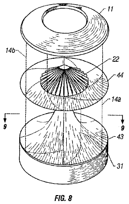
Fig.8 is a perspective view of
the embodiment of Fig.1 with the
toroidal longitudinal baffles 14a and 14b drawn in
phantom so that the annular central divider (mid-deck) 44 and turbine 22
can be seen.
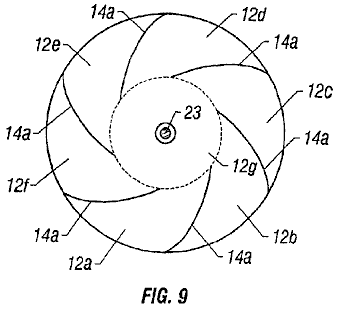
Fig.9 is a horizontal
cross-sectional view of the embodiment of Fig.1
taken along line 9 — 9 of Fig.8.
In this view, it can be seen that the upstream annular chamber 12 is
divided into a set of smaller chambers 12a through 12f by
the toroidal longitudinal baffles 14a.
The interior ends of the longitudinal baffles define a central vortex
chamber 12g (illustrated by a dashed circle) in which the
upstream vortex is formed, and from which the upstream vortex enters the
turbine 22. The central vortex
chamber 12g has a diameter approximately equal to the diameter of
the turbine.

Fig.10 is a perspective view of
a second embodiment of the present invention that converts wind energy to
mechanical or electrical energy, with the longitudinal baffles 14a and
14b drawn in phantom so that a set of hinged longitudinal louvers
61a and 61b can be seen. The hinged louvers are
mounted in the openings between the longitudinal baffles. The louvers may be mounted in a circular
configuration anywhere from the outside edge of the longitudinal baffles to the
inside edge of the baffles. In the
version shown, the louvers are longitudinally mounted at the inside edge of the
baffles, around the perimeter of the central vortex chamber 12g. Each of the louvers is hinged on one side
(i.e., the windward side as wind enters through the baffles) so that the louver
may be opened toward the central vortex chamber by the force of the incoming
wind. The width of each louver is
slightly greater than the distance between louvers so that each louver slightly
overlaps the hinged edge of the next louver.
This prevents the louvers from opening outward.

In Fig.11 there is shown a horizontal cross-sectional view of the
embodiment of Fig.10 taken along
line 11 — 11. During operation, wind blowing in the direction
shown from the outside of the energy conversion device is funnelled by the
toroidal longitudinal baffles 14a into upstream chambers 12a
and 12b. The baffles block
the wind from entering the other chambers 12c through 12f. The wind flows through chambers 12a
and 12b, and enters the central vortex chamber 12g by
opening the hinged longitudinal louvers 61a which are mounted
between the baffles in the openings defining chambers 12a and 12b. The remaining louvers remain closed,
preventing the wind from exiting through the sides of the device. Thus, the wind-activated louvers are, in
effect, one-way valves allowing the wind to flow into the central vortex
chamber through the sides of the device, but only allowing the wind to exit
through the top of the chamber, and through the turbine 22.
Referring again to Fig.10, it can be seen that the
longitudinal louvers 61a mounted in the upstream chamber 12 are
hinged on the opposite side from the louvers 61b mounted in the
downstream chamber 13. This is
because the vortex in the downstream chamber rotates in the opposite direction
from the vortex in the upstream chamber, and the downstream toroidal baffles 14b
funnel the wind into the louvers 61b in the opposite
direction. Like the louvers 61a
in the upstream chamber 12, the louvers 61b in the
downstream chamber 13 act as one-way valves allowing the wind to flow
into the central vortex chamber through the sides of the device, but only
allowing the wind to exit through the top of the chamber, and out of the
device. This configuration helps to
maintain the strength of both the upstream and the downstream vortices during
operation of the device.
It should be recognized that some
degree of improved energy-conversion performance may be obtained in a
configuration in which there are toroidal baffles 14a and hinged
louvers 61a only in the upstream annular chamber 12 because
this ensures that all of the wind or other fluid entering the sides of the
upstream chamber flows through the turbine.
The addition of toroidal baffles 14b in the downstream
annular chamber 13 provides additional improved performance,
particularly when the direction of rotation of the downstream vortex is
opposite the direction of the upstream vortex.
Optimum energy-conversion performance is provided by a device having
oppositely configured toroidal baffles 14a and 14b, and
oppositely hinged louvers 61a and 61b, for both the
upstream annular chamber 12 and the downstream annular chamber 13.
It is to be understood that even
though numerous characteristics and advantages of the present invention have been
set forth in the foregoing description, the disclosure is illustrative only,
and changes may be made in detail, especially in matters of size, shape, and
arrangement of parts within the principles of the invention to the full extent
indicated by the broad general meaning of the terms in which the appended
claims are expressed.
The
‘Hotsabi’ Booster
Here are the full step-by-step instructions
for making a very simple single-cell booster design from “HoTsAbI” - a member of the Yahoo ‘watercar’ forum
group. This is a very neat and simple
electrolysis booster unit which has raised the average mpg from 18 to 27 (50%
increase) on his 1992 5-litre Chevy Caprice.
Caution: This is not a toy. If you make and use one of these, you do so
entirely at your own risk. Neither the
designer of the booster, the author of this document or the provider of the
internet display are in any way liable should you suffer any loss or damage
through your own actions. While it is
believed to be entirely safe to make and use a booster of this design, provided
that the safety instructions shown below are followed, it is stressed that the
responsibility is yours and yours alone.
The unit draws 15 amps which is easily
handled by the existing vehicle alternator.
The construction uses ABS
(Acrylonitrile Butadiene Styrene) plastic tubing with an electrolyte
containing Sodium Hydroxide (NaOH – sold in
The circuit is wired so that it is only
powered up when the car ignition switch is closed. A relay feeds power to the electrolyser which
is three inches (75 mm) in diameter and about 10 inches (250 mm) tall. The
electrolyser circuit is protected by a 30-amp circuit breaker. The electrolyser has several stainless steel
wire mesh screens above the water surface:
The output of the electrolyser is fed to a
steam trap, also fitted with several stainless steel wire mesh screens, and
then on via a one-way valve into a safety bubbler. The bubbler also has stainless steel wire mesh
screens which the gas has to pass through before it exits the bubbler. The gas is then passed through an
air-compressor style water trap to remove any remaining moisture, and is
injected into the air intake of the vehicle.
Although not shown in the diagram, the containers are protected by
pop-out fittings which provide extra protection in the extremely unlikely event
of any of the small volumes of gas being ignited by any means whatsoever.
The ammeter is used to indicate when
water should be added to the electrolyser, which is typically, after about 80
hours of driving and is done through a plastic screw cap on the top of the
electrolyser cap (shown clearly in the first photograph). This unit used to be available commercially but
the designer is now too busy to make them up, so he has generously published
the plans free as shown here.
The designer says: please read all of these instructions
carefully and completely before starting your project. This project is the construction of an
electrolyser unit which is intended to improve the running of a vehicle by
adding gases produced by the electrolysis of water, to the air drawn into the
engine when it is running. There is no
magic about this. The ‘HHO’ gas produced
by the electrolysis acts as an igniter for the normal fuel used by the
vehicle. This produces a much better
burn quality, extracting extra energy from the normal fuel, giving better
pulling power, smoother running, cooler engine operation, the cleaning out of
old carbon deposits inside the engine and generally extending the engine life.
ELECTROLYSER PARTS LIST
1. One 7 inch long x 3 inch diameter piece of ABS
tubing cut with square ends - de-burr the edges
2. One 3 inch (75 mm) diameter ABS Plug - clean
out the threaded cap
3. One
Threaded adaptor DWV 3 inch (75 mm) diameter HXFPT threaded cap ("DWV" and "HXFPT" are
male and female threaded sewer-type plastic caps)
4. One 3 inch (75 mm) diameter ABS cap
5. One 4 inch (100 mm) Stainless steel cap screw
1/4 x 20
6. Two stainless steel 1 inch long (25 mm) 1/4 x 20 cap screw
7. One 10/32 inch x 1/4 inch stainless steel
screw
8. Five washers and Eight stainless steel nuts
1/4 x 20
9. One piece of stainless steel shimstock 11 inch
x 6 inch 0.003 inch thick
10. One
piece of stainless steel 14 gauge wire mesh
8 inch x 3 inch
11. One
3/8 inch nylon plug
12. One
¼ inch x ¼ inch NPT (National Pipe Tap) barbed fitting
13. Plumbers
tape
TOOLS LIST
1. Hand
drill
2. Tin
Snips (for cutting steel mesh and shimstock)
3. ¼
inch NPT tap and 5/16 inch drill bit
4. 3/8
inch NPT tap and ½ inch drill bit
5. 10/32
inch tap and 1/8 inch drill bit
6. One
clamp and a piece of 1 inch x 1 inch wood strip
7. Hexagonal
key "T-handle" wrench to fit the capscrew
8. Philips
screwdriver
9. Small
adjustable wrench

Cut and fit shimstock into ABS tubing, 11 inch works well as this gives
a 1 inch overlap.
For drilling, use a strip of wood. Be sure that the shimstock is flush with at
least one edge of the tube. Use the
flush edge as the bottom of the electrolyser.
Clamp securely and drill two 0.165 inch
holes, one on either side, perpendicular to each other, as best you can. These holes will be tapped 1/4 inch x 20
The shimstock holes need to be reamed out to
accept the capscrew.
Note: This is why 2 holes are drilled (to
facilitate assembly). Next, attach the
electrode inside the barrel. It is important to us a stainless steel nut
inside to seat the capscrew.
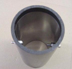
Note that the shimstock is flush with the
bottom of the tube. Final assembly for
the electrodes. Note that the capscrews
each have stainless steel nuts inside the barrel to seat to the shimstock. The screw on the left will be used as the
Negative battery connection to the cell while the screw on the right merely
seats the shimstock.
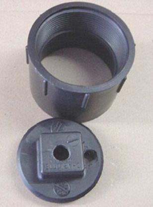
The upper component is a Threaded Adaptor
DWV 3 inch HXFPT. The lower component is
a 3 inch ABS Plug, clean out the threaded cap.
Prepare the top cap and plug:
Drill and tap a 3/8 inch diameter NPT in the centre of the threaded cap
(this is the main filling plug). Drill
and tap a 1/4 inch NPT on the side (to take the barbed fitting).
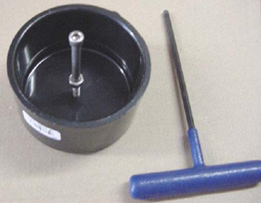
Prepare the bottom cap: Drill and tap 1/4 inch x 20 hole in the centre. Install the capscrew with a stainless steel
nut. Tighten and install a washer and
stainless steel nut outside.
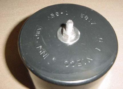
This is the Positive battery connection.
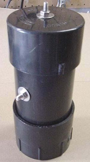
This is the finished cell shown here upside
down. Assemble the unit using ABS glue.

Next, prepare the stainless steel mesh.
Cut it carefully to fit inside the threaded cap. Use at least 3 pieces.
After fitting the mesh tightly into the cap,
mount it with a 10/32 inch stainless steel screw on the opposite side to the
1/4 inch tapped hole for the barbed fitting.
This is a flame arrestor, so make CERTAIN that the entire inside is
covered tightly. Note that the sides
wrap up. Turn each layer to cross the
grain of the mesh in the successive layers.
Use white "plumber's tape" on all
threaded fittings.
This unit has raised the average
miles-per-gallon performance of my 1992 5-litre Chevy Caprice from 18 to 27 mpg
which is a 50% increase. It allows a
very neat, professional-looking installation which works very well:
All of the 3/8 inch plastic fittings
including one way valves, come from Ryanherco and are made of Kynar to
withstand heat. The water trap is from
an air compressor. The 3/16 inch tubing
or hose is also high-heat type from automatic transmission coolant lines. I use Direct Current and limited with a
thermal breaker and LYE mixture adjustment.
If you need help then e-mail hotsabi (at) gmail (dot) com (put
"e-cell" in the title of your mail).
Comments by Patrick Kelly:
This design is very simple to
construct, but as it is just a single cell with the whole of the vehicle’s
voltage placed across it, a good deal of the electrical power goes in heating
the electrolyte rather than making the wanted hydroxy gas.
If there is sufficient space to fit
two in, then using two allows you use half the current and that halves the heat
generated in the units and doubles the length of time between topping up the
unit with water:
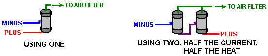
Please don’t get the impression that
if a small amount of HHO gas produces a very beneficial effect on the running
of a vehicle, that adding much more HHO gas will give even better results, as
that is not the case. Each vehicle is
different and will have a different optimum flow rate of HHO gas and if that
optimum rate is exceeded, then although the mpg improvement may actually be
reduced rather than increased. If in
doubt, start will a low current (with more dilute electrolyte) which will
produce less gas and see what the mpg results are. Then try a slightly stronger mix and check
the mpg over several gallons of fuel.
This will allow you to determine the booster current at which your
particular vehicle operates best. This
is not a competition to see who can produce the highest gas output, instead, it
is a process to find out what the highest mpg your vehicle can give when using
this simple booster design.
Mixing the electrolyte:
Please remember that the sodium hydroxide or ‘lye’ (Lowes store: Roebic
‘Heavy Duty’ Crystal Drain Opener) is a strongly caustic substance which needs
to be treated with care.
Always store it in a sturdy air-tight
container which is clearly labelled "DANGER! - Sodium
Hydroxide". Keep the container in
a safe place, where it can’t be reached by children, pets or people who won't
take any notice of the label. If your
supply of sodium hydroxide is in a strong plastic bag, then once you open the
bag, you should transfer all its contents to a sturdy, air-tight, plastic
storage container, which you can open and close without risking spilling the
contents. Hardware stores sell plastic
buckets with air tight lids that can be used for this purpose.
When working with dry flakes or granules,
wear safety goggles, rubber gloves, a long sleeved shirt, socks and long
trousers. Also, don’t wear your
favourite clothes when handling hydroxy solution as it is not the best thing to
get on clothes. It is also good practice
to wear a face mask which covers your mouth and nose. If you are mixing solid sodium hydroxide with
water, always add the hydroxide to the water, and not the other way round, and
use a plastic container for the mixing, preferably one which has double the
capacity of the finished mixture. The
mixing should be done in a well-ventilated area which is not draughty as air
currents can blow the dry hydroxide around.
When mixing the electrolyte, never
use warm water. The water should be cool
because the chemical reaction between the water and the hydroxide generates a
good deal of heat. If possible, place
the mixing container in a larger container filled with cold water, as that will
help to keep the temperature down, and if your mixture should “boil over” it
will contain the spillage. Add only a
small amount of hydroxide at a time, stirring continuously, and if you stop
stirring for any reason, put the lids back on all containers.
If, in spite of all precautions, you get
some hydroxide solution on your skin, wash it off with plenty of running cold
water and apply some vinegar to the skin.
Vinegar is acidic, and will help balance out the alkalinity of the
hydroxide. You can use lemon juice if
you don't have vinegar to hand - but it is always recommended to keep a bottle
of vinegar handy.
The
‘Smacks’ Booster
The Smack’s Booster is a piece of equipment
which increases the mpg performance of a car or motorcycle, and reduces the
harmful emissions dramatically. It does
this by using some current from the vehicle’s battery to break water into a
mixture of hydrogen and oxygen gasses called “hydroxy” gas which is then added
to the air which is being drawn into the engine. The hydroxy gas improves the quality of the
fuel burn inside the engine, increases the engine power, cleans old carbon
deposits off the inside of an old engine, reduces the unwanted exhaust
emissions and improves the mpg figures under all driving conditions, provided
that the fuel computer does not try to pump excess fuel into the engine when it
detects the much improved quality of the exhaust.
This hydroxy booster is easy to make and the
components don’t cost much. The
technical performance of the unit is very good as it produces 1.7 litres of
hydroxy gas per minute at a very reasonable current draw. This is how to make
and use it.
Caution: This is not a toy. If you make and use one of these, you do so
entirely at your own risk. Neither the
designer of the booster, the author of this document or the provider of the
internet display are in any way liable should you suffer any loss or damage
through your own actions. While it is
believed to be entirely safe to make and use a booster of this design, provided
that the safety instructions shown below are followed, it is stressed that the
responsibility is yours and yours alone.
The Safety Gear
Before getting into the details of how to
construct the booster, you must be aware of what needs to be done when using
any booster of any design. Firstly,
hydroxy gas is highly explosive. If it
wasn’t, it would not be able to do it’s job of improving the explosions inside
your engine. Hydroxy gas needs to be
treated with respect and caution. It is
important to make sure that it goes into the engine and nowhere else. It is also important that it gets ignited
inside the engine and nowhere else.
To make these things happen, a number of
common-sense steps need to be taken.
Firstly, the booster must not make hydroxy gas when the engine is not
running. The best way to arrange this is
to switch off the current going to the booster.
It is not sufficient to just have a manually-operated dashboard
On/Off switch as it is almost certain that switching off will be forgotten one
day. Instead, the electrical supply to
the booster is routed through the ignition switch of the vehicle. That way, when the engine is turned off and
the ignition key removed, it is certain that the booster is turned off as well.
So as not to put too much current through
the ignition switch, and to allow for the possibility of the ignition switch
being on when the engine is not running, instead of wiring the booster directly
to the switch, it is better to wire a standard automotive relay across the oil
pressure sending unit and let the relay carry the booster current. If the engine stops running, the oil pressure
drops and if the booster is connected as shown, then this will also power down
the booster.
An extra safety feature is to allow for the
(very unlikely) possibility of an electrical short-circuit occurring in the
booster or its wiring. This is done by
putting a fuse or contact-breaker between the battery and the new circuitry as
shown in this sketch:
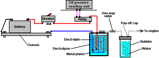
If you choose to use a contact-breaker, then
a light-emitting diode (“LED”) with a current limiting resistor of say, 680 ohms
in series with it, can be wired directly across the contacts of the circuit
breaker. The LED can be mounted on the
dashboard. As the contacts are normally
closed, they short-circuit the LED and so no light shows. If the circuit-breaker is tripped, then the
LED will light up to show that the circuit-breaker has operated. The current through the LED is so low that
the electrolyser is effectively switched off when the contact breaker opens. This is not a necessary feature, merely an
optional extra:

In the first sketch, you will notice that
the booster contains a number of metal plates and the current passing through
the liquid inside the booster (the “electrolyte”) between these plates, causes
the water to break up into the required hydroxy gas mix. A very important safety item is the “bubbler”
which is just a simple container with some water in it. The bubbler has the gas coming in at the
bottom and bubbling up through the water.
The gas collects above the water surface and is then drawn into the
engine through an outlet pipe above the water surface. To prevent water being drawn into the booster
when the booster is off and cools down, a one-way valve is placed in the pipe
between the booster and the bubbler.
If the engine happens to produce a backfire,
then the bubbler blocks the flame from passing back through the pipe and
igniting the gas being produced in the booster.
If the booster is made with a tightly-fitting lid rather than a screw-on
lid, then if the gas in the bubbler is ignited, it will just blow the lid off
the bubbler and rob the explosion of any real force. A bubbler is a very simple, very cheap and
very sensible thing to install. It also
removes any traces of electrolyte fumes from the gas before it is drawn into
the engine.
You will notice that the wires going to the
plates inside the electrolyser are both connected well below the surface of the
liquid. This is to avoid the possibility
of a connection working loose with the vibration of the vehicle and causing a
spark in the gas-filled region above the surface of the liquid, and this volume
is kept as low as possible as another safety feature.
The Design
The booster is made from a length of 4-inch
diameter PVC pipe, two caps, several metal plates, a couple of metal straps and
some other minor bits and pieces.
This is not rocket science, and this booster
can be built by anybody. A clever extra
feature is the transparent plastic tube added to the side of the booster, to
show the level of the liquid inside the booster without having to unscrew the
cap. Another neat feature is the very
compact transparent bubbler which is actually attached to the booster and which
shows the gas flow coming from the booster.
The main PVC booster pipe length can be adjusted to suit the available
space beside the engine.
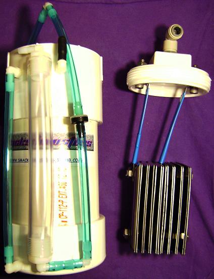
Bubbler connections close up:

This booster uses cheap, standard electrical
stainless steel wall switch covers from the local hardware store and stainless
steel straps cut from the handles of a wide range of stainless steel
food-preparation ladles:
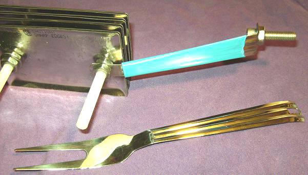
The electrical cover plates are clamped
together in an array of eight closely-spaced pairs of covers. The plates are held in a vise and the holes
drilled out to the larger size needed.
The covers are further treated by being clamped to a workbench and
dented using a centre-punch and hammer.
These indentations raise the gas output from 1.5 lpm to 1.7 lpm as the
both increase the surface area of the cover and provide points from which the
gas bubbles can drop off the cover more easily.
The more indentations the better.
The active surfaces of the plates - that is,
the surfaces which are 1.6 mm apart from each other, need to be prepared
carefully. To do this, these surfaces
are scored in an X-pattern using 36-grade coarse sandpaper. Doing this creates miniature sharp-crested
bumps covering the entire surface of each of these plates. This type of surface helps the hydroxy
bubbles break away from the surface as soon as they are formed. It also increases the effective surface area
of the plate by about 40%. I know that
it may seem a little fussy, but it has been found that fingerprints on the
plates of any electrolyser seriously hinder the gas production because they
reduce the working area of the plate quite substantially. It is important then, to either avoid all
fingerprints (by wearing clean rubber gloves) or finish the plates by cleaning
all grease and dirt off the working surfaces with a good solvent, which is
washed off afterwards with distilled water.
Wearing clean rubber gloves is by far the better option as cleaning
chemicals are not a good thing to be applying to these important surfaces.
Shown above are typical hand tools used to
create the indentations on the plates.
The active plate surfaces – that is, the surfaces which are 1.6 mm apart
– are indented as well as being sanded.
An array of these prepared plates is
suspended inside a container made from 4-inch (100 mm) diameter PVC pipe. The pipe is converted to a container by using
PVC glue to attach an end-cap on one end and a screw-cap fitting on the
other. The container then has the
gas-supply pipe fitting attached to the cap, which is drilled with two holes to
allow the connecting straps for the plate array to be bolted to the cap, as
shown here:
In order to ensure that the stainless steel
straps are tightly connected to the electric wiring, the cap bolts are both
located on the robust, horizontal surface of the cap, and clamped securely both
inside and out. A rubber washer or rubber
gasket is used to enhance the seal on the outside of the cap. If available, a steel washer with integral
rubber facing can be used.
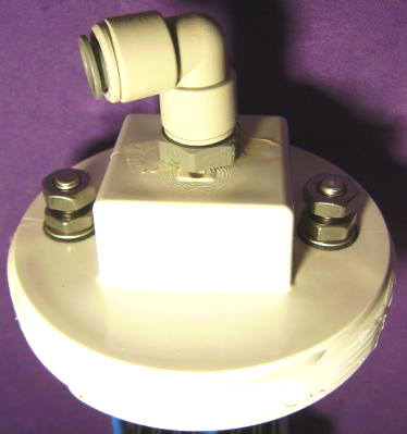
As the stainless steel strap which connects
the booster plates to the negative side of the electrical supply connects to
the central section of the plate array, it is necessary to kink it
inwards. The angle used for this is in
no way important, but the strap should be perfectly vertical when it reaches
the plates.
The picture above shows clearly the wall
plates being used and how the bubbler is attached to the body of the booster
with super-glue. It also shows the
various pipe connections. The stainless
steel switch-cover plates are 2.75 inch x 4.5 inch (70 mm x 115 mm) in size and
their existing mounting holes are drilled out to 5/16 inch (8 mm) diameter in
order to take the plastic bolts used to hold the plates together to make an
array. After a year of continuous use,
these plates are still shiny and not corroded in any way.
Three stainless steel straps are used to
connect the plate array together and connect it to the screw cap of the
booster. These straps are taken from the
handles of cooking utensils and they connect to the outer two plates at the top
and the third strap runs across the bottom of the plate array, clear of the
plates, and connects to both outside plates as can be seen in the diagrams.
The plates are held in position by two
plastic bolts which run through the original mounting holes in the plates. The arrangement is to have a small 1.6 mm gap
between each of eight pairs of plates.
These gaps are produced by putting plastic washers on the plastic bolts
between each pair of plates.
The most important spacing here is the 1.6
mm gap between the plates as this spacing has been found to be very effective
in the electrolysis process. The way
that the battery is connected is unusual in that it leaves most of the plates
apparently unconnected. These plate
pairs are called “floaters” and they do produce gas in spite of looking as if
they are not electrically connected (they are connected through the
electrolyte).
Stainless steel nuts are used between each
pair of plates and these form an electrical connection between adjacent
plates. The plate array made in this way
is cheap, easy to construct and both compact and robust. The electrical straps are bolted to the screw
cap at the top of the unit and this both positions the plate array securely and
provides electrical connection bolts on the outside of the cap while
maintaining an airtight seal for the holes in the cap.

Another very practical point is that the
stainless steel straps running from the screw cap to the plate array, need to
be insulated so that current does not leak directly between them through the
electrolyte. The same applies to the
strap which runs underneath the plates.
This insulating is best done with shrink-wrap. Alternatively, good quality tool dip
(McMaster Carr part number 9560t71) is an effective method, but if neither of
these methods can be used, then the insulating can be done by wrapping the
straps in electrical insulating tape.
Using that method, the tape is wrapped tightly around the straps, being
stretched slightly as it is wrapped. The
section running underneath the covers is insulated before the array is
assembled.
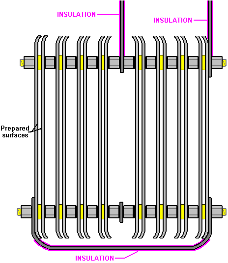
The PVC housing for the booster has two
small-diameter angle pipe fittings attached to it and a piece of clear plastic
tubing placed between them so that the level of the electrolyte can be checked
without removing the screw cap. The
white tube on the other side of the booster is a compact bubbler which is glued
directly to the body of the booster using super-glue in order to produce a
single combined booster/bubbler unit.
The bubbler arrangement is shown here, spread out before gluing in place
as this makes the method of connection easier to see.
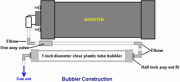
The half-inch diameter elbows at the ends of
the one-inch diameter bubbler tube have their threads coated with silicone
before being pushed into place. This
allows both of them to act as pressure-relief pop-out fittings in the unlikely
event of the gas being ignited. This is
an added safety feature of the design.
This booster is operated with a solution of
Potassium Hydroxide also called KOH or Caustic Potash which can be bought from
various suppliers such as:
http://www.essentialdepot.com/servlet/the-13/2-lbs-Potassium-Hydroxide/Detail
http://www.organic-creations.com/servlet/the-653/caustic-potassium-hydroxide-KOH/Detail
http://www.aaa-chemicals.com/pohy2posa.html
or
http://www.nuscentscandle.com/PHFLAKES.html To get the right amount in the booster, I
fill the booster to its normal liquid level with distilled water and add the
Hydroxide a little at a time, until the current through the booster is about 4
amps below my chosen working current of 20 amps. This allows for the unit heating up when it
is working and drawing more current because the electrolyte is hot. The amount of KOH is typically 2
teaspoonfuls. It is very important to
use distilled water as tap water has impurities in it which make a mess which
will clog up the booster. Also, be very
careful handling potassium hydroxide as it is highly caustic. If any gets on you, wash it off immediately
with large amounts of water, and if necessary, use some vinegar which is acidic
and will offset the caustic splashes.
The completed booster usually looks like
this:
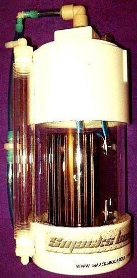
But, it can be built using
different materials to give it a cool look:

And attached to a cool bike:

The final important thing is how the booster
gets connected to the engine. The normal
mounting for the booster is close to the carburettor or throttle body so that a
short length of piping can be used to connect the booster to the intake of the
engine. The connection can be to the air
box which houses the filter, or into the intake tube. The closer to the butterfly valve the better,
because for safety reasons, we want to reduce the volume of hydroxy gas hanging
around in the intake system. You can
drill and tap a 1/4" (6 mm) NPT fitting into the plastic inlet tubing with
a barbed end for connecting the 1/4" (6 mm) hose.
The shorter the run of tubing to the air
ductwork of the engine, the better.
Again, for safety reasons, we want to limit the amount of unprotected
hydroxy gas. If a long run of 3 feet (1
metre) or more must be used due to space constraints, then it would be a good
idea to add another bubbler at the end of the tube, for additional
protection. If you do this, then it is
better to use a larger diameter outlet hose, say 3/8" or 5/16” (10 mm or 8
mm).
If you don’t have the necessary tools or
workspace, then I will make one of these boosters for you. You can see the details on the Smack’s web
site at http://www.smacksboosters.110mb.com. The parts needed to build this booster with
it’s bubbler can be found locally or ordered from web sites.
Powering your Booster
Use
wire and electrical hardware capable of handling 20 amps DC, no less. Overkill is OK in this situation, so I
recommend using components that can handle 30 amps. Run your power through your ignition circuit,
so that it only runs when the vehicle is on.
A 30 amp relay should be used to prevent damaging the ignition circuit
which may not be designed for an extra 20 amp draw. Make sure to use a properly rated fuse, 30
amps is ideal. You can use a toggle
switch if you like for further control. As an added safety feature, some like
to run an oil pressure switch to the relay as well, so the unit operates only
when the engine is actually running. It
is very important that all electrical connections be solid and secure. Soldering is better than crimping. Any loose connections will cause heat and
possibly a fire, so it is up to you to make sure those connections are of high
quality. They must be clean and tight,
and should be checked from time to time as you operate the unit just to be sure
the system is secure.
Adjusting the Electrolyte
Fill your booster with distilled water and
NaOH (sodium hydroxide) or KOH (potassium hydroxide) only. No tap water, salt water or rainwater! No table salt or baking soda! These materials will permanently damage the
booster!
First, fill the booster with distilled water
about 2" from the top. Add a
teaspoon of KOH or NaOH to the water and then slide the top into place. Do not tighten it for now, but leave the top
loose and resting in place. Connect your
12V power supply to the leads and monitor the current draw of the unit. You want 16 amps flowing when the booster is
cold. As the water heats up over time,
the current draw will increase by around 4 amps until it reaches about 20 amps,
and this is why you are aiming for only 16 amps with a cold system.
If the current is too high, dump out some
electrolyte and add just distilled water.
If the current is too low, add a pinch or two at a time of your catalyst
until the 16 amps is reached.
Overfilling your booster will cause some of the electrolyte to be forced
up the output tube, so a liquid level tube was added to monitor electrolyte
level.
The booster generally needs to be topped off
once a week, depending on how long it is in operation. Add distilled water, then check your current
draw again. You may observe a drop in
current over the course of a few refills, and this is normal. Some of the catalyst escapes the cell
suspended in water vapour droplets, so from time to time you may need to add a
pinch or two. The water in the bubbler
acts to scrub this contaminant out of the gas as well. I highly recommend installing an ammeter to
monitor current draw as you operate your booster.
Mounting the Booster
Choose a well ventilated area in the engine
compartment to mount your booster. Since
every vehicle design is different, I leave it up to you to figure out the best
method to mount it. It must be mounted
with the top orientated upwards. Large
5" diameter hose clamps work well, but do not over tighten them or the PVC
may deform. I recommend mounting the
booster behind the front bumper in the area usually present between it and the
radiator. Support the weight of the unit
from the bottom with a bracket of your design, then use two hose clamps to
secure the unit, one near the top and one near the bottom. Never install the unit in the passenger
compartment for safety reasons.
Output hose and Bubbler
The bubbler on the side of the unit should
be filled about 1/3 to 1/2 full of water - tap water is fine for the bubbler. The check valve before the bubbler is there
to prevent the bubbler water from being sucked back into the booster when it
cools and the gases inside contract. Make
sure the bubbler level is maintained at all times. Failure to do so could result in an unwanted
backfire explosion. That water
inside the bubbler is your physical shield between the stored hydroxy volume in
the generator and the intake of your engine.
Install the output hose as close to the carburettor/throttle body as
close as possible by making a connection into the intake tube/air cleaner. Try to make the hose as short as possible to
reduce the amount of gas volume it contains. I recommend using the same type of
1/4" poly hose that is used on the unit.
Here is a list of the parts needed to
construct the booster and bubbler if you decide to build it yourself rather
than buying a ready-made unit:
The Main Parts
Needed
|
Part |
Quantity |
Comment |
|
4-inch diameter PVC pipe 12-inches long |
1 |
Forms the body of the booster |
|
4-inch diameter PVC pipe end-cap |
1 |
Closes the bottom of the booster |
|
4-inch diameter PVC pipe screw cap |
1 |
The top of the booster |
|
90-degree Quick Connect Outlet fitting |
1 |
3/8" O.D. Tube x 1/4" NPT from Hardware store |
|
Level indicator Nylon barbed tube fitting |
2 |
1/4" Tube x 1/8" NPT Part Number 2974K153 or from your local
hardware store |
|
Quarter-inch I.D. Poly sight tube |
8” |
Water-level indicator tubing - Hardware store |
|
Stainless steel switch covers |
16 |
The plate array components |
|
Stainless steel straps 12-inches long |
2 |
The electrical connections to the plates |
|
3/4" Inside Diameter Clear poly tube |
12-inch |
From your local hardware store |
|
5/16” stainless steel bolts 1.25” long |
2 |
Electrical strap connection to the top cap |
|
5/16” stainless steel nuts & washers |
6 each |
To fit the steel bolts in the cap |
|
5/16” diameter nylon threaded rod |
8” min. |
Nylon Threaded Rod 5/16"-18 Thread. McMaster Carr Part No 98831a030 |
|
5/16” inch nylon washers 1.6 mm thick |
1-pack |
Nylon 6/6 Flat Washer 5/16", Pack of 100 McMaster Carr Part No
90295a160 |
|
5/16”-18 s/s jam nuts (7/32" thick) |
20 |
McMaster Carr Part No 91841A030 |
|
90 degree Bubbler Fittings |
2 |
1/4" Barbed Tube 1/2" NPT.
McMaster Carr Part No 2974K156 |
|
Check valve |
1 |
1/4" tube, McMaster Carr Part No 47245K27 or from your local
Hardware store |
|
PVC glue |
1 tube |
Same colour as the PVC pipe if possible |
|
5/16" Neoprene sealing washer |
2 |
McMaster Carr Part No 94709A318 or from
your local Hardware store |
|
Tool dip – 14.5 oz |
1 |
McMaster Carr Part No 9560t71 |
|
|
|
|
|
Optional:
Light Emitting Diode |
1 |
10 mm diameter, red, with panel-mounting
clip |
|
Quarter-watt resistor |
1 |
470 ohm (code bands: Yellow, Purple,
Brown) |
Now, having shown how this very effective
booster and bubbler are constructed, it should be pointed out that if you use it
with a vehicle fitted with an Electronic Control Unit which monitors fuel
injection into the engine, then the fuel-computer section will offset the gains
and benefits of using this, or any other, booster. The solution is not difficult, as the
fuel-computer can be controlled by adding in a little circuit board to adjust
the sensor signal fed to the computer from the oxygen sensor built into the
exhaust of the vehicle. Ready-built
units are available for this or you can make your own. If you want to make your own, then the web
site document http://www.free-energy-info.com/D17.pdf
shows you how and as well, points to Eagle-Research, the suppliers of
alternative, ready-made units, also stocked by The Hydrogen Garage.
Quite an amount of testing and experimenting
has been carried out by many of the people who have made copies of this booster
and two variations which have been found to be helpful are shown here:
Firstly, in spite of the very restricted
space inside the housing, it is possible to introduce two extra wall plates,
one at each end of the plate stack.
These plates are spaced 1.6 mm apart using plastic washers and this
triple-plate group causes an extra voltage drop across the sub-set of three
plates. The construction is then as
shown here:
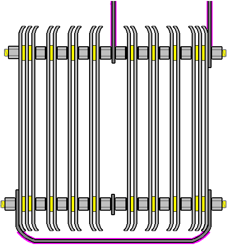
The second modification is wrapping the
plate array in 4-inch shrink-wrap. This
wrapping extends around the sides of the plates and helps by cutting out some
of the unwanted electrical leakage paths through the electrolyte. This arrangement is shown here:
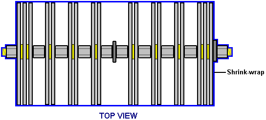
Enjoy using this booster and do your part in cutting greenhouse gas
emissions.
Eletrik
Smack’s Booster is a trademarked name, and the
design is patent-pending but remains fully disclosed for public use.
Date of release of this copy of the document:
3rd July 2008
Background Information
Many people find the plate arrangement of
the Smack’s Booster, rather difficult to understand, so this additional section
is just to try to explain the operation of the cell. This has nothing to do with actually building
or using a Smack’s Booster, so you can just skip this section without missing
anything.
The Smack's Booster plate arrangement does
look confusing. This is mainly because
Eletrik has squeezed two identical sets of plates into one container as shown
here:
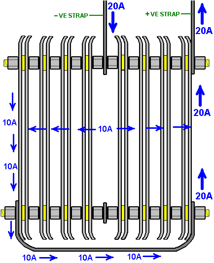
This arrangement is two identical sets of
plates positioned back-to-back. To make
it easier to understand the operation, let’s just consider just one of the two
sets of plates.
Here, you have just the electrical Plus linked
to the electrical Minus by a set of four pairs of plates in a daisy chain (the
technical term is: connected "in series" or
"series-connected"). Easily
the most electrically efficient way for doing this is to exclude all possible
current flow paths through the electrolyte by closing off around the edges of
all the plates and forcing the current to flow through the plates and only
through the plates.
Unfortunately, this is very difficult to do
in a cylindrical container and it has the disadvantage that it is difficult to
keep the unit topped up with water and difficult to maintain the electrolyte
level just below the top of the plates.
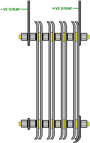
So, a compromise is reached where the
current flow around and past the plates is combatted by strategic spacing of
the plates:
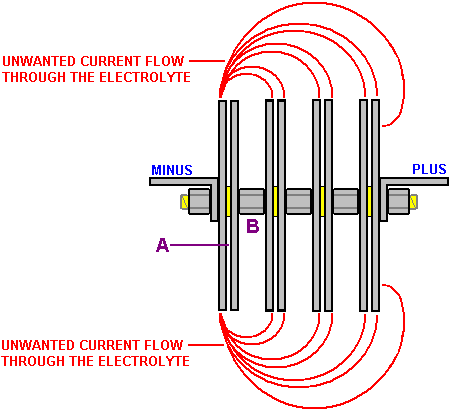
This diagram shows the way that the plates
are connected. The red lines show paths
of unwanted current flow which produce almost no gas. This wasted current flow is opposed by the
useful current flow across gap "A" in the diagram.
To favour the flow across the 1.6 mm gap
"A", an attempt is made to make the waste flows as long as
possible by comparison. This is done by
the gap "B" being made as large as possible, limited only by
the size of the booster housing.
The voltage applied to the cell (13.8 volts
when the engine is running) divides equally across the four plate pairs, so
there will be one quarter of that voltage (3.45 volts) across each plate pair.
If you look again at the original diagram,
you will see that there are two of these sets of four plate pairs, positioned
back-to-back in the container. Each of
these acts separately, except for the fact that there are additional current
leakage paths through the electrolyte between the plates of one set and the
plates of the second set.
There is a steady voltage drop progressively
across the array of plates. Remember
that they are connected in pairs in the middle due to the metal-to-metal
connection created by the steel nuts between the plates:
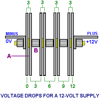
It is often difficult for people to get the
hang of how the voltage drops across a chain of resistors (or matrix of
plates). The voltages are relative to
each other, so each plate pair thinks that it has a negative electrical
connection on one plate and a positive connection on the other plate.
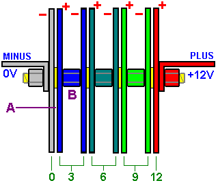
For example, if I am standing at the bottom
of a hill and my friend is standing ten feet up the hill, then he is ten feet
above me.
If we both climb a hundred feet up the
mountain and he is at a height of 110 feet and I am at a height of 100 feet, he
is still ten feet above me.
If we both climb another hundred feet up the
mountain and he is at a height of 210 feet and I am at a height of 200 feet, he
is still ten feet above me. From his
point of view, I am always ten feet below him.
The same thing applies to these plate
voltages. If you one plate is at a
voltage of +3 volts and the plate 1.6 mm away from it is at a voltage of +6
volts, then the 6 volt plate is 3 volts more positive than the 3 volt plate, and
there is a 3 volt difference across the gap between the two plates. The first plate looks to be 3 volts negative
to the 6 volt plate when it “looks” back at it.
You can also say that the +3 volt plate is 3
volts lower than the +6 volt plate, so from the point of view of the +6 volt
plate, the +3 volt plate is 3 volts lower down than it, and it therefore “sees”
the other plate as being at -3 volts relative to it.
In the same way, my friend sees me as being
at -10 feet relative to him, no matter what height we are on the mountain. It is all a matter of being "higher
up" whether in terms of height above sea level on a mountain or in terms
of higher up in voltage inside a booster.
Now, having shown how this booster and bubbler are constructed, it
should be pointed out that if you use it with a vehicle fitted with an
Electronic Control Unit which monitors fuel injection into the engine, then the
fuel-computer section will offset the mpg gains and benefits of using this, or
any other, booster. The solution is not
difficult, as the fuel-computer can be controlled by adding in a little circuit
board to adjust the sensor signal fed to the computer from the oxygen sensor
built into the exhaust of the vehicle, to allow for the improved quality of the
fuel being burnt in the engine. This is
necessary because the exhaust will be so much cleaner than it used to be, that
the computer will think that the engine is being starved of fuel (which it most
definitely isn’t. With a booster, the
engine runs cleaner, cooler and more smoothly and it has enhanced pulling power
called “torque”. Ready-built units are
available for correcting the oxygen sensor signal for the improved situation,
or alternatively, you can make your own.
Dealing with the Vehicle
Computer
When an mpg. improving device such as an electrolyser is fitted to a vehicle, the result does not always produce better mpg. figures. Older vehicles which are fitted with a carburettor will see an immediate improvement. This is not the case for more recent vehicles which come with computer control of the fuel sent to the engine.
When an electrolyser is attached to the engine, it causes the fuel burn inside the cylinders to be greatly improved, with a corresponding improvement in engine performance. Unfortunately, the fuel computer is expecting the same amount of unburnt oxygen to come out of the engine, and when it doesn’t detect it, the computer increases the fuel flow rate in an attempt to get back to it’s normal, inefficient method of running. That action cancels the mpg improvement produced by the electrolyser unless something is done to adjust the operation of the computer.
In the most simple terms, most vehicles which have an Electronic Control Unit (“ECU”) to control the fuel flow are fitted with one of two types of exhaust sensor. The majority have a “narrowband” sensor while the remainder have a “wideband” sensor. The ideal mix of air to fuel is considered to be 14.7 to 1. A narrowband sensor only responds to mixtures from about 14.2 to 1 through 14.9 to 1. The sensor operates by comparing the amount of oxygen in the exhaust gas to the amount of oxygen in the air outside the vehicle and it generates an output voltage which moves rapidly between 0.2 volts where the mixture is too lean, and 0.8 volts when it passes below the 14.7 to 1 air/fuel mix point where the mixture is too rich (as indicated by the graph shown below). The ECU increases the fuel feed when the signal level is 0.2 volts and decreases it when the signal voltage is 0.8 volts. This causes the signal voltage to switch regularly from high to low and back to high again as the computer attempts to match the amount of “too lean” time to the amount of “too rich” time.

A simple control circuit board can be added to alter the sensor signal and nudge the fuel computer into producing slightly better air/fuel mixes. Unfortunately, there is a severe downside to doing this. If, for any reason, the fuel mix is set too high for an extended period, then the excess fuel being burnt in the catalytic converter can raise the temperature there high enough to melt the internal components of the converter. On the other hand, if the circuit board is switched to a mix which is too lean, then the engine temperature can be pushed high enough to damage the valves, which is an expensive mistake.
Over-lean
running can occur at different speeds and loads. Joe Hanson recommends that if any device for
making the mix leaner is fitted to the vehicle, then the following procedure
should be carried out. Buy a “type K”
thermocouple with a 3-inch stainless steel threaded shank, custom built by
ThermX Southwest of
Drive the vehicle long enough to reach normal running temperature and then drive at full speed on a highway. Note the temperature reading at this speed. When a leaner mix is used, make sure that the temperature reading under exactly the same conditions does not exceed 180 degrees Fahrenheit (100 degrees Centigrade) above the pre-modification temperature.
David Andruczyk recommends an alternative method of avoiding engine damage through over-lean fuel/air mixtures, namely, replacing the narrowband oxygen sensor with a wideband sensor and controller. A wideband oxygen sensor reads a very wide range of Air/Fuel ratios, from about 9 to 1 through 28 to 1. A normal car engine can run from about 10 to 1 (very rich) to about 17.5 to 1 (pretty lean). Maximum engine power is developed at a mix ratio of about 12.5 to 1. Complete fuel combustion takes place with a mix of about 14.7 to 1, while the mix which gives minimum exhaust emissions is slightly leaner than that.
Unlike narrowband sensors, wideband sensors need their own controller in order to function. There are many of these units being offered for sale for retro-fitting to existing vehicles which have just narrowband oxygen sensor systems. David’s personal recommendation is the Innovate Motorsports LC-1 which is small, and uses the very reasonably priced LSU-4 sensor. This wideband controller can be programmed. Most controllers have the ability to output two signals, the wideband signal suitable for running to a gauge or new ECU, plus a synthesised narrowband signal which can feed an existing ECU. The trick is to install a wideband sensor, with the LC-1 controller and then reprogram it to shift the narrowband output to achieve a leaner mix as shown here:
|
Actual Air/Fuel Mix |
Wideband Output |
Original Narrowband Output |
Shifted Narrowband Output |
|
9 to 1 |
9 to 1 |
Mix is too Rich |
Mix is too Rich |
|
10 to 1 |
10 to 1 |
Mix is too Rich |
Mix is too Rich |
|
11 to 1 |
11 to 1 |
Mix is too Rich |
Mix is too Rich |
|
12 to 1 |
12 to 1 |
Mix is too Rich |
Mix is too Rich |
|
13 to 1 |
13 to 1 |
Mix is too Rich |
Mix is too Rich |
|
14 to 1 |
14 to 1 |
Mix is too Rich |
Mix is too Rich |
|
14.6 to 1 |
14.6 to 1 |
Mix is too Rich |
Mix is too Rich |
|
14.8 to 1 |
14.8 to 1 |
Mix is too Lean |
Mix is too Rich |
|
15 to 1 |
15 to 1 |
Mix is too Lean |
Mix is too Rich |
|
15.5 to 1 |
15.5 to 1 |
Mix is too Lean |
Mix is too Lean |
|
16 to 1 |
16 to 1 |
Mix is too Lean |
Mix is too Lean |
|
18 to 1 |
18 to 1 |
Mix is too Lean |
Mix is too Lean |
This system allows you to set the narrowband “toggle point” very precisely on an exact chosen air/fuel ratio. This is something which it is nearly impossible to do accurately with a circuit board which just shifts a narrowband oxygen signal as you just do not know what the air/fuel ratio really is with a narrowband sensor.
However, for anyone who wants to try adding a circuit board to alter a narrowband sensor signal to produce a leaner mix on a vehicle, the following description may be of help. It is possible to buy a ready-made circuit board, although using a completely different operating technique, from the very reputable Eagle Research, via their website: http://www.eagle-research.com/products/pfuels.html where the relevant item is shown like this:

This unit generates a small voltage, using a 555 timer chip as an oscillator, rectifying the output to give a small adjustable voltage which is then added to whatever voltage is being generated by the oxygen sensor. This voltage is adjusted at installation time and is then left permanently at that setting. Eagle Research also offer for sale, a booklet which shows you how to build this unit from scratch if you would prefer to do that.
I understand that at the present time, the purchase price of this device is approximately US $50, but that needs to be checked if you decide to buy one. Alternatively, instructions for building a suitable equivalent circuit board are provided later on in this document.
If you wish to use a circuit board with a narrowband oxygen sensor, then please be aware that there are several versions of this type of sensor. The version is indicated by the number of connecting wires:
Those with 1 wire, where the wire carries the signal and the case is ground (zero volts)
Those with 2 wires, where one wire carries the signal and the other wire is ground.
Those with 3 wires, where 2 (typically slightly thicker) wires are for a sensor heater, and
1 for the signal while the case is ground.
Those with 4 wires (the most common on current model cars), where there are
2 (slightly heavier) for the sensor heater,
1 for the signal , and
1 for the signal ground.
(Sensors with 5 wires are normally wideband devices.)
Look in the engine compartment and locate the oxygen sensor. If you have difficulty in finding it, get a copy of the Clymer or Haynes Maintenance Manual for your vehicle as that will show you the position. We need to identify the sensor wire which carries the control signal to the fuel control computer. To do this, make sure that the car is switched off, then
For 3 and 4 wire sensors:
Disconnect the oxygen sensor wiring harness,
Set a multimeter to a DC voltage measurement range of at least 15 volts,
Turn on the ignition and probe the socket looking for the two wires that provide 12 volts.
These are the heater wires, so make a note of which they are,
Shut the ignition off, and reconnect the oxygen sensor.
The two remaining wires can now be treated the same as the wires from a 2-wire sensor, one will carry the sensor signal and one will be the signal ground (for a single wire sensor, the signal ground will be the engine block). Jesper Ingerslev points out that the Ford Mustang built since 1996 has 2 oxygen sensors per catalytic converter, one before the converter and one after. Some other vehicles also have this arrangement. With a vehicle of this type, the circuit board described here should be attached to the sensor closest to the engine.
Find a convenient place along the wires. Don’t cut these wires, you will cut the sensor wire here at a later time, but not now. Instead, strip back a small amount of the insulation on each wire. Be careful to avoid the wires short-circuiting to each other or to the body of the vehicle. Connect the DC voltmeter to the wires (the non- heater wires). Start the engine and watch the meter readings. When the engine is warmed up, if the oxygen sensor is performing as it should (i.e. no engine check lights on), the voltage on the meter should begin toggling between a low value near zero volts and a high value of about 1 volt. If the meter reading is going negative, then reverse the leads. The black multimeter lead is connected to the signal 'ground' (zero volts) and the red lead will be connected to the wire which carries the signal from the sensor. Connect a piece of insulated wire to the stripped point of the sensor wire and take the wire to the input of your mixture controller circuit board. Connect a second insulated wire between the signal ‘ground’ wire, or in the case of a 1-wire sensor, the engine block, and the circuit board zero-volts line. Insulate all of the stripped cables to prevent any possibility of a short-circuit:
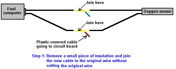
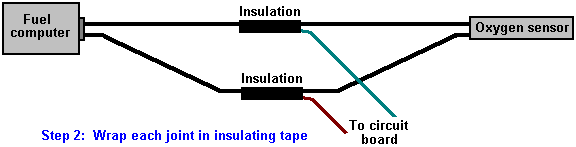
More specific detail
However, the situation is by no means a simple one which allows a single simple adaption which will work on every vehicle for many years. Les Pearson has been investigating this situation in depth for three years along with a friend who is an Electronics Engineer. Having built and tested EFIEs, the oxygen sensor circuit shown below, several versions of MAP controllers, coolant/air temperature hacks, professional systems, etc. and discovered that many vehicle ECUs ("Electronic Control Units") learnt to adapt to the new conditions and return to the highly inefficient excess fuel injection condition. This return to the original fuel injection is different for each design of ECU and there are many different designs.
Les says: "To understand the solution, first you have to understand the dilemma with all the other ECU control tricks. The EFIEs, MAP adjusters, temp hacks etc. do get good results for a short time, and then the performance deteriorates again. Why should this be? It is because the ECU learns to deal with the new situation with them in place. This is because the ECU knows that the feedback from most of it's controls, and sensor's are not linear, nor should they be. All of the electronics, and adjustment methods used by the Hydrogen On Demand people are linear, and that is not an adequate way to deal with the problem.
For example, we may add a couple of hundred millivolts to the oxygen ("lambda") sensor signal in order to return an unduly rich signal to the ECU, and so make it respond with a lower level of fuel injection. This makes the ECU think that the Air/Fuel Ratio is say, 15:1 or 20:1. Now the mass air maps are all wrong, we need to show less air so that the ECU adds less fuel in order to match the fuel trims. We now need to adjust the ignition timing to take advantage of this combustion change. The problem is that all the EFIEs, MAP/MAF adjusters, and attempts at changing timing by manipulating air temp are a static fixed offset, producing just a single change.
An Air/Fuel Ratio of 20:1 is not appropriate under moderate or heavy acceleration when you don't, and usually can't, add enough hydroxy gas to allow for these conditions. A set 15% to 20% leaner setting across the entire fuel map is not appropriate at all loads, and engine speeds. Adding 50 to 75 degrees F to the air temp is not appropriate when the outside air is already at 110 degrees F. The ECU knows this and makes appropriate changes to it's long-term settings, and so it cancels out the changes which our electronic additions have made.
While it may be OK for an experimenter, and mechanic with all the tools at his disposal to play with these techniques, and retune his engines every week or so in order to get great mileage, it is not realistic to expect the average person to do this. The cost in equipment alone, would undermine any fuel savings. Also, most people don't even change their oil at appropriate intervals.
This was my train of thought as I pondered a solution, and began searching. My search was for a control solution which could firstly, alter the air-flow readings, lambda readings, and ignition timing and secondly, respond to changes in engine speed and engine load. To my surprise I found several products already on the market which are capable of doing this, and which have been available for quite some time. People in the engine-tuning industry have been using them for years. They are custom programmable, piggy-back chips. Several companies make them, and while most do not advertise O2 ("lambda") sensor control, many are quite capable of altering it.
We became a distributor for one brand which seemed to be the best fit for our purposes, and we began testing. The results are perfect. We started with an 2002 Saturn SL. The average mpg for this car started at 26 mpg (highway and city combined). We installed the chip, tested several tuning methods, and found the one which worked best. The car now averages 44-46 mpg. This is not special 'grandma driving' to try, and coax a few extra miles per gallon. This is a courier vehicle for a local printer, and it is driven daily like it was stolen. We have all the same benefits of increased torque (pulling power), better throttle response, etc. The car has been driven around for three months now with our programmed chip installed, and it achieves the mid-40s in mpg all of the time. there are no code changes needed, no start-up problems, no driving problems of any kind whatsoever. If you weren't told, you would never know that hydroxy gas was being added, except for the fact that you can go over 500 miles on a single tank of fuel.
The only
problem is that this is definitely not a do-it-yourself solution. You need a laptop computer with proprietary
software to tune the chip, and the scanning, and diagnostic equipment to know
when you have it tuned correctly. However, I have thought of a do-it-yourself
solution. It still requires you to buy a
few electronic kits, and you need a lot of know-how, but we are circumventing a
highly sophisticated control architecture, so anyone who thinks it will be
easy, is delusional. The main item is a
Digital Fuel Adjuster or "DFA" kit from JayCar electronics based in
After the two adjusters and the controller have been built, the first one is wired in to the MAP/MAF sensor signal as shown in the instructions guide. Next the second DFA is used on the oxygen sensor signal. If there are two oxygen sensors, then the DFA is wired through the common ground for the upstream sensors ONLY. This places the voltage offsets in tandem, which makes it unnecessary to use two DFAs (or EFIEs for that matter) for "lambda" control. Now control has been established over fuel maps, and a "lambda" control which is responsive to engine load has been achieved. I believe that these kits also come with an option to make them responsive to rpm.
For ignition timing, the temperature offsets will probably still be necessary, but now you have a fuel control which if tuned properly, the ECU will not learn its way around. I have found that the maps for "lambda" control are very simple. Tune for the leanest Air/Fuel Ratio appropriate at very low loads, and increase the fuel richness a bit in increments as the load increases. As you get close to full throttle, but before you switch to open-loop operation, your lambda offset should be zero (the stock setting). To tune the air-flow or fuel maps, watch the OBD II scan gauge, and decrease the MAP signal so that your short term fuel trim ("STFT" on a scanner) is no greater than about ± 7% at each load interval. Drive for about 20 minutes, and check that your long term fuel trim ("LTFT") never goes beyond the "7s" either. Now the ECU cannot "see" your changes because the fuel map, and lambda readings "agree" at every load range.
The Jaycar kits are not as sophisticated as the chip sets, but they are about 20% of the cost, if you want to put the time and effort into them. The adjuster itself simply adds to, or subtracts from, whatever voltage runs across them, and it can be set to change that offset value in correspondence to whatever voltage value is present at the signal input pin. You would of course put your TPS signal to the signal input pin. The device itself is very versatile, and could be used for many different applications. If you wanted to use one to control a Pulse-Width Modulator attached to a cell, then that would be possible and it would provide a variable gas rate that responds to changes in engine load. I hope you can put this to good use, and feel free to spread the word around. Perhaps you know someone who could build a similar device or give us a schematic to build one, after looking at a JayCar kit. The only drawback to the kits is that rpm sampling gets a little complex, and while I don't think it is absolutely necessary, it would be beneficial. Although the kits have only 125 data points between the "closed", and "fully open" throttle settings, and do not interpolate between data points, they seem to work very well. The professional chip sets have 96,000 data points between CT ("Closed Throttle"), and WOT ("Wide-Open Throttle"), and they do logically interpolate between set data points. The professional chip sets run about $650 USD programmed, and installed.
I plan to market a pre-programmed chip capable of making any hydroxy system work. While I plan to have a profitable venture with the professional pre-programmed architecture, I also believe in the open source do-it-yourself community, which is where I got started. The chips I plan to sell will be a 'plug and play' device. You send me the info on the type of vehicle you are modifying, and the efficiency data of your cell, and I'll be able to send you a chip that will make your ECU work with those conditions. The Do-it-yourself version would be quite time consuming but, would work for less than one quarter of the price.
I think that the "more is better" hydroxy gas idea that a lot of
people are stuck in, is seriously flawed. There is definitely a point of
diminishing returns. I tune most systems
to deliver about 1 lpm. The lower the
amperage you can do this at, of course the better. I have found that not only does it take more
amperage to produce higher volumes at a less effective rate of return, but it
does not add much to the efficiency of the "boosting". With the cells which I build I get 1 lpm of
hydroxy gas at about 8 to 10 amps. I'm
using direct DC with a 5-cell, 6 plate array, similar to a "Smack's
Booster", but with better plate isolation in the bath. We've spent thousands developing fancier, and
slightly more efficient cells. We've
used PWMs to get better production, and be able to attenuate gas
production with duty cycle. We had a
really, really advanced system. Then I applied Occam's razor to it. We can make enough gas to
support ultra-lean combustion above fairly low load conditions - so what
good is it to be able to decrease when you barely make enough already? The PWM does help, and is relatively
inexpensive so we kept that component if the customer wants, but we don't
change the duty cycle.
The 6 plate "Smacks" style cell works fine. It is small, easy to build, and is efficient enough for the production we need. Engine control was the biggest issue. I can get great mileage with just a little hydroxy gas, if I can control what fuel table the ECU looks at every load range, and rpm. The problem with EFIEs, and MAP/MAF adjusters is that they tell the computer to look at inappropriate fuel tables at higher load ranges. The ECU picks up on that, adjusts it's long-term fuel trims, and goes back to an unmodified state. If I can make the ECU look at very lean tables at cruise, and then more or less unmodified tables at higher loads it never "sees" the trick. Since we only make enough hydroxy gas to affect low loads anyway, that is all I need to be concerned with. You could think of it as an ultra-lean cruise mode: when you aren't at low cruise you aren't changing anything. When you are cruising you are running at a very lean Air-Fuel Ratio. So far, it works great.
The super fancy system that used a PWM with a duty-cycle controlled by our chip, and made up to 3 lpm at 20amps would have cost over USD $2500 just for the parts, and equipment to cover production cost, and turn a profit, and it only gained us about 10% efficiency. The system we are working on now should be less than USD $1500 as a 'turn-key' system. Our little Saturn just came back at 88mpg on a carefully driven run with this system. It typically gets high 40s to mid 50s in mpg under normal driving conditions.
I have tried adding just 0.6 lpm or so, and letting the ECU trim out to
compensate. This has given me mixed
results. Sometimes I can get 25% to 30%
reduction in consumption, and sometimes it makes no difference at all. It has a lot to do with the ECU's
programming, and the driver's habits. I
don't really know why it doesn't work all the time theoretically it should. The
hydroxy gas makes the petrol more volatile so you should be getting more energy
per gram of fuel. That should correlate
to higher exhaust gas temperatures, and the ECU should see that and take away
some fuel, but sometimes it does just the opposite. The ECU sees a lean condition due to
increased Exhaust Gas Temperature at the manifold, and lower temperature at the
catalytic converter, and so it richens up the air-fuel mix.
Another possible option that I have not explored would be
an EFIE designed to change it's output to a set voltage controlled by
the vehicle's throttle position sensor. The challenge here is that it is
not a linear change. The steps between load sites would not be equal. They
would need to be able to be manually set for what the application needed. The DFAs allow you to do this, and can add
voltage just like an EFIE. You can use
one DFA for MAP/MAF control, and one for oxygen sensor control. So even with a modified EFIE you would need a
DFA or something similar to provide non-linear MAP/MAF control". You can contact Les at lespearson (at)
hotmail (dot) com.
Construction
If you wish to build an oxygen sensor controller circuit, then here is a suggestion as to how you might do it. This description assumes very little knowledge on the part of the reader, so I offer my apologies to those of you who are already expert in these matters. There are many different ways to design and construct any electronic circuit and each electronics expert will have his own preferred way. In my opinion, the way shown here is the easiest for a newcomer to understand and build with the minimum of tools and materials.
The circuit shown here, is taken from the website http://better-mileage.com/memberadx.html, and is discussed here in greater detail. This circuit can be constructed on a printed circuit board or it can be built on a simple single-sided stripboard as shown here:

Stripboard (often called “Veroboard”), has copper strips attached to one side of the board. The copper strips can be broken where it is convenient for building the circuit. Component leads are cut to length, cleaned, inserted from the side of the board which does not have the copper strips, and the leads attached to the copper strips using a solder joint. Soldering is not a difficult skill to learn and the method is described later in this document.
When all of the components have been attached to the stripboard and the circuit tested, then the board is mounted in a small plastic case as shown here:
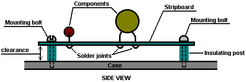
Insulating posts can be made from a short pieces of plastic rod with a hole drilled through its length. The mounting bolt can self-tap into a hole drilled in the case, if the hole is slightly smaller than the diameter of the bolt threads. Alternatively, the holes can be drilled slightly larger and the bolt heads located outside the case with nuts used to hold the board in place. This style of mounting holds the circuit board securely in place and gives some clearance between the board and the case.

You will need building equipment, namely, a soldering iron, a 12 volt power supply such as a battery pack and an accurate digital volt meter for this project. If the 12 volt supply is a main-powered unit, then it needs to be a well-filtered, voltage-stabilised unit. Lastly, you will need a variable voltage source that can go from 0 to 1 volt to imitate the output from the vehicle’s oxygen sensor when testing the completed circuit board. This is simple enough to make, using a resistor and a variable resistor.
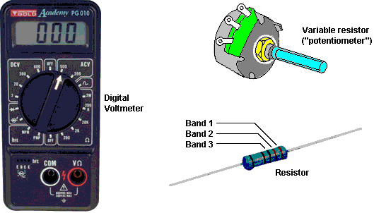
A series of components will be needed for the circuit itself. These can be bought from a number of different suppliers and the ordering details are shown later in this document. Shown above is a resistor. The value of the resistor is indicated by a set of three colour bands at one end of the body. The reason for doing this rather than just writing the value on the resistor, is that when the resistor is soldered in place, its value can be read from any angle and from any side. The component list shows the colour bands for each of the resistors used in this circuit. If you want more information on basic electronics, then read the Electronics Tutorial which can be found at http://www.free-energy-info.co.uk /Chapter12.pdf
Other components which you will be using, look like this:
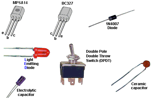
The MPSA14 and the BC327 devices are transistors. They each have a “Collector”, a “Base” and an “Emitter” wire coming out of them. Please notice that the two packages are not identical, and take care that the right wire is placed in the correct hole in the stripboard before soldering it in place.
The 1N4007 diode has a ring marked at one end of the body. The ring indicates the flat bar across the symbol as shown on the circuit diagram, and in that way it identifies which way round the diode is placed on the stripboard.
The Light-Emitting Diode (the “LED”) will be familiar to most people as it is used so extensively in equipment of all types.
The toggle switch has six contacts - three on each side. The centre contact is connected to one of the two outer contacts on its side, which one, depends on the position of the switch lever.
The two capacitors (which are called “condensers” in very old literature) look quite different from each other. The electrolytic capacitor has it’s + wire marked on the body of the capacitor, while the ceramic has such a small value that it does not matter which way round it is connected.
The main component of the circuit, is an integrated circuit or “chip”. This is a tiny package containing a whole electronic circuit inside it (resistors, capacitors, diodes, whatever, ....). Integrated circuit chips generally look like this:
A very common version of this package has two rows of seven pins each and it goes by the grandiose name of “Dual In Line” which just means that there are two rows of pins, each row having the pins in a straight line. In our particular circuit, the chip has eighteen pins, in two rows of nine.
Now to the circuit itself. If you find it hard to follow, then take a look at the electronics tutorial on the web site as it shows the circuit diagram symbol for each component and explains how each device works.
The circuit contains three capacitors, eight resistors, two diodes, one LED, one IC chip, two transistors, one toggle switch and two types of component not yet described, namely: two preset resistors and one rotary switch.
The preset resistor is very small and is adjusted using a flat bladed screwdriver. It is used for making an adjustable setting which is then left unchanged for a long time. The Rotary switch has a central contact which is connected to a row of outer contacts in turn when the shaft is rotated from position to position. The switch shaft is made of plastic and so can easily be cut to the length needed to make a neat installation, and the knob is locked in place by tightening its grub screw against the flat face of the shaft, although some knobs are designed just to push tightly on to the shaft. There is a wide range of knob styles which can be used with this switch, so the choice of knob is dictated by personal taste.
This is the circuit diagram:
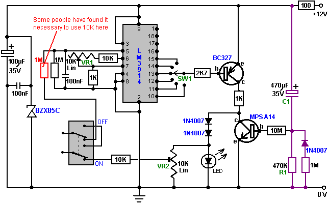
Electronic circuits are normally “read” from left to right, so we will look at this circuit that way. The first components are the 100 microfarad, 35 volt electrolytic capacitor with the tiny 100 nF capacitor across it. These are put there to help iron out any variations in the voltage supply. The BZX85C zener diode is a 24-volt type and it protects the integrated circuit from voltage spikes coming along the +12-volt line from other equipment in the vehicle, preventing the circuit from being fed more than 24 volts for even a fraction of a second as that would damage the integrated circuit.
The next item is the On/Off dashboard switch. When switched to its Off position as shown here:

the connection from the oxygen sensor is passed straight through to the vehicle’s fuel computer, bypassing the circuit board completely. This switch allows the whole circuit to be switched Off should you want to do this for any reason.
In it’s On position, as shown in the circuit diagram, the varying voltage signal coming from the oxygen sensor is passed into the circuit, and the output voltage from the circuit is passed back to the fuel computer, instead of the original sensor voltage. This allows the circuit to manipulate the voltage sent to the fuel computer.
The next set of components (four resistors, one ceramic capacitor and one preset resistor) shown here:
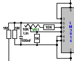
are needed to feed the incoming sensor voltage to the Integrated Circuit chip, and make the chip operate in the way that we want, (the chip manufacturer allows more than one way for the chip to work). You can just ignore these components for now, just understand why they are there.
The Integrated Circuit chip has ten outputs, coming out through Pins 1 and 10 through 18 inclusive:
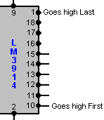
If the input voltage coming from the oxygen sensor is low, then all of these ten outputs will have low voltages on them. When the input voltage rises a little, the voltage on Pin 10 suddenly rises to a high value, while the other output pins still have low voltages.
If the input voltage rises a little higher, then suddenly the voltage on Pin 11 rises to a high value. At this point, both Pin 10 and Pin 11 have high voltage on them and the other eight output pins remain at low voltage.
If the input voltage rises a little higher again, then suddenly the voltage on Pin 12 rises to a high value. At this point, Pin 10, Pin 11 and Pin 12 all have high voltage on them and the other seven output pins remain at low voltage.
The same thing happens to each of the ten output pins, with the voltage on Pin 1 being the last to get a high voltage on it. The circuit is arranged so that Pin 10 provides the output signal for the richest air/fuel mixture for the vehicle, and the mix gets progressively leaner as the output on Pins 11, 12, ... etc. are selected to be fed to the fuel computer.
As there is the possibility of engine damage if the fuel mix is too lean, only six of the outputs are taken on into the circuit. However, if the engine is being fed hydroxy gas from an electrolyser to improve both the miles per gallon performance and reduce emissions to zero, then it is likely that the engine will run cooler than before and engine damage is most unlikely to occur. It is quite safe to leave the remaining output pins of the Integrated Circuit chip unconnected. However, if this unit is to be used with the Nitrogen Hydroxide cell described in the D18.pdf document, then it is quite safe to connect Pins 16, 17, 18 and 1 and set the rotary switch to ten positions.
The output pin to be used by the remainder of the circuit is selected by the rotary switch mounted on the dashboard:
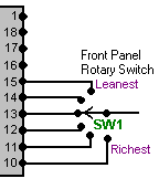
A standard single-pole rotary wafer switch has twelve positions but the switch operation can be restricted to any lesser number of positions by placing the end-stop lug of the switch just after the last switch position required. This lug comes as standard, fits around the switch shaft like a washer, and is held in place when the locking nut is tightened on the shaft to hold the switch in place. The lug projects down into the switch mechanism and forms an end-stop to prevent the switch shaft being turned any further. With six switch positions, the circuit provides five levels of leaner air/fuel mix which can be selected. This should be more than adequate for all practical purposes.
The next section of the circuit is the BC327 transistor amplifier stage which provides the output current for the fuel computer:
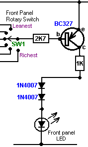
Here, the switch “SW1” connects to one of the output pins of the Integrated Circuit. When the voltage on that pin goes low, it causes a current to flow through the transistor Base/Emitter junction, limited by the 2.7K (2,700 ohm) resistor. This current causes the transistor to switch hard On, which in turn alters the voltage on its Collector from near 0 volts to near +12 volts. The 2.7K resistor is only there to limit the current through the transistor and to avoid excessive loading on the output pin of the IC.
The transistor now feeds current to the LED via the two 1N4007 diodes and the 1K (1,000 ohm) resistor. This causes the Light Emitting Diode to light brightly. The 1K resistor is there to limit the amount of current flowing through this section of the circuit.
Part of the voltage across the LED is fed back to the fuel computer:
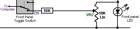
By moving the slider contact on the preset resistor “VR2”, any output voltage can be fed to the fuel computer. This voltage can be anything from the whole of the voltage across the LED, down to almost zero volts. We will use VR2 to adjust the output voltage when we are setting the circuit up for use. In this circuit, VR2 is acting as a “voltage divider” and it is there to allow adjustment of the output voltage going from the circuit to the fuel computer.
The final section of the circuit is the MPSA14 transistor and its associated components:
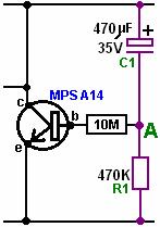
This circuit is a timer. When the circuit is first powered up (by the vehicle’s ignition key being turned), the 470 microfarad capacitor “C1” is fully discharged (if it isn’t, then the oxygen sensor will already be hot). As it is discharged and one side is connected to the +12 volt line, then the other side (point “A”) looks as if it is also at +12 volts. This provides a tiny current to the Base/Emitter junction of the MPSA14 transistor, through the high resistance 470K (470,000 ohm) resistor. The MPSA14 transistor has a very high gain and so this tiny current causes it to switch hard on, short-circuiting the LED and preventing any voltage developing across the LED.
As time passes, the tiny current flowing through the MPSA14 transistor, along with the tiny current through the 3.9M (3,900,000 ohm) resistor “R1”, cause a voltage to build up on capacitor “C1”. This in turn, forces the voltage at point “A” lower and lower. Eventually, the voltage at point “A” gets so low that the MPSA14 transistor gets starved of current and it switches off, allowing the LED to light and the circuit to start supplying an output voltage to the fuel computer. The purpose of the section of the circuit is to shut off the output to the fuel computer until the oxygen sensor has reached it’s working temperature of 600 degrees Fahrenheit. It may be necessary to tailor this delay to your vehicle by altering the value of either “R1” or “C1”. Increasing either or both will lengthen the delay while reducing the value of either or both, will shorten the delay.
We want the time delay to occur if the engine is off for some time, but not to occur if the engine is switched off only briefly. For this to happen, it is suggested that a diode is placed across the timing resistor. This will have no effect when the circuit is powered up, but it will discharge the capacitor when the circuit is powered down. We can slow down the rate of discharge by putting a high-value resistor in series with the discharge diode and that would make the circuit:
Circuit Operation:
Now that we have looked at each part of the circuit separately, let us look again at the way that the circuit operates. The main component is the LM3914 integrated circuit. This device is designed to light a row of Light Emitting Diodes (“LEDs”). The number of LEDs lit is proportional to the input voltage reaching it through it’s Pin 5. In this circuit, the integrated circuit is used to provide a reduced voltage to be fed to the fuel computer, rather than to light a row of LEDs. When the operating switch is set in it’s ON position, the sensor voltage is fed to Pin 5 through a 1 megohm resistor.
The sensitivity of this circuit is adjusted, so that when 500 millivolts (0.5 volts) is applied to Pin 5, the output on Pin 10 is just triggered. This is done by adjusting the 10K linear preset resistor “VR1” while placing a test voltage of 500 millivolts on Pin 5. This LM3914 Integrated Circuit is normally switched so that it samples the sensor voltage. The LM3914 chip provides ten separate output voltage levels, and the circuit is arranged so that any one of several of these can be selected by the rotary switch “SW1”. These output voltages range from 50 millivolts on Pin 1 to 500 millivolts on Pin 10, with each output position having a 50 millivolt greater output than it’s neighbouring pin. This allows a wide range of control over the sensor feed passed to the fuel computer.
The input resistor/capacitor circuit provides filtering of the sensor signal. Because this circuit draws very little current, it is easily knocked out of correct operation through it’s input line picking up stray electrical pulses produced by the engine, particularly the vehicle’s ignition circuit. When the exhaust sensor heats up, the signal becomes cleaner and then the circuit starts operating correctly. The circuit includes a delay so that after start up, the output is held low for a few minutes to simulate a cold sensor. The sensor must be operating correctly before we send signals to the computer. The most common problem, if we don’t have this delay, is that the output will be high simply from the noise on the signal line. The computer will think the sensor is working, because it is high, and will cut back the fuel to make the signal go low. If that were to happen, we would end up with an over-lean fuel input to the engine, producing very poor acceleration.
The front panel LED is not just to show that the device is operating, but forms a simple voltage regulator for the output signal to the computer. When the engine is warmed up and running normally, the LED is lit when the output is high, and not lit when the output is low, so this LED should be flashing on and off.
The earth connection for the oxygen sensor is the exhaust system, which is firmly bolted to the engine. The computer earth is the vehicle body. A difference of just 0.5 volts can make a large difference to the mixture. If the engine is not securely earthed to the vehicle body, then a voltage difference can exist between the two, and in this situation a voltage difference of just 0.5 volts would normally go unnoticed. We can’t afford to have that sort of voltage difference when trying to control the mixture accurately, so some investigation and adjustment is needed.
To do this, start the engine, switch the headlights on to high beam, then measure the voltage between the engine and the body. Use a digital volt meter. Any more than 50 millivolts (0.05 volts) means that there is a bad earth connection which need cleaning and tightening. Modern cars usually have more than one connection so look around. If you have trouble achieving a really good connection, then earth your circuit board directly on the engine rather than connecting it to a point on the bodywork of the vehicle. The most important item is to have a good quality signal voltage coming from the sensor, since the operating range consists of quite low voltages. The components and tools needed for building this circuit are shown later, but for now, consider the setting up and testing of the unit so as to understand better what is needed.
Adjusting on the Bench
When the circuit has been constructed to the testing stage, that is, with all components in place except for the timing capacitor “C1”, and before the power is turned on, plug the Integrated Circuit chip into its socket mounted on the board. Be very careful doing this as the chip can be destroyed by static electricity picked up by your body. Professionals wear an electrical earth wrist strap when handling these devices, so it would be a good idea to touch a good earth point such as a metal-pipe cold water system just before handling the chip.
It is vital that you install the IC chip, the correct way round or it may be damaged. The circuit board layout shows which way round it goes. The chip has a semi-circular indentation at one end to show which end is which, so be careful that the indentation is positioned as shown on the board layout in the section which shows how the board is built. Some manufacturers use a dot rather than a semi-circular indentation to mark the end of the chip which has Pin 1 in it.
Make up the test voltage device. We need something to give us an adjustable voltage in the range 0 to 1 volt. A very easy way to get this is to use a 10K resistor and a 1K variable resistor (called a “potentiometer” by some people) and connect them across the 12 volt battery, as shown here:
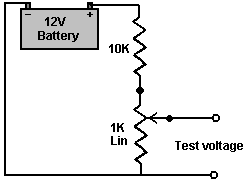
This gives us a voltage in the correct range when the shaft of the variable resistor is turned. Power up the circuit board by switching the 12 volt battery through to the board. Adjust the test-voltage source to 500 millivolts (0.5 volts) and apply it to the board’s input (where the sensor connection will be made when it is installed in the vehicle). Set the switch to the “Richest” position, that is, with the switch connected to Pin 10 of the chip.
Now, using a flat-blade screwdriver, adjust the sensitivity control preset resistor “VR1” so that the output LED is just lit. Leave the preset resistor in that position and adjust the test voltage lower and higher to test that the LED turns on and off in response to the varying voltage at the input to the circuit. The LED should come on at 0.5 volts, and go off just below 0.5 volts. The other outputs, which can be selected by the rotary switch “SW1”, will be about 50 millivolts lower for each position of the switch away from it’s “Richest” setting on Pin 10.
Now, with the output high and the LED lit, use a flat-bladed screwdriver to adjust the preset resistor “VR2” to set the output voltage being sent to the computer to about 1.0 volts. When this has been set, lower the input voltage so that the LED goes out. The output voltage should now be at zero volts. If this is what happens, then it shows that the circuit is operating correctly.
If this board is not in place, the sensor will cause the fuel computer to make the fuel mixture richer so as to maintain a 500 millivolt voltage from the sensor. With the circuit in place and set to its “Richest” setting, exactly the same thing happens. However, if the rotary switch is moved to its next position, the fuel computer will maintain the fuel feed to maintain a 450 millivolt output, which is a leaner fuel-to-air mixture. One step further around and the fuel computer will make the mix even leaner to maintain a 400 millivolt output from the circuit board, which the fuel computer thinks is coming from the exhaust oxygen sensor.
If your circuit board does not operate as described, then power it down and examine the circuit board again, looking for places where the solder connections are not perfect. There may be somewhere where the solder is bridging between two of the copper strips, or there may be a joint which looks as if it is not a good quality joint. If you find one, don’t solder anywhere near the IC chip as the heat might damage the chip. If necessary, earth yourself again, remove the chip and put it back into the anti-static packaging it came in, before repairing the board. If the components are all correctly positioned, the copper tracks broken at all the right places and all solder joints looking good and well made but the board still is not working correctly, then it is likely that the IC chip is defective and needs to be replaced.
Next, install the delay capacitor “C1”. Set the test voltage above 500 millivolts and turn the power on again. It should take about three minutes for the LED to come on. If you want to shorten this delay, then change the timing resistor “R1” for a resistor of a lower value. To lengthen the delay, replace the timing capacitor “C1” with a capacitor of larger value. If you find that the oxygen sensor heats up quickly, then you can reduce the length of the delay. Having too long a delay is not ideal, since the computer will be adding extra fuel to make the mixture richer.
It is suggested that the rotary switch should be set to have only six switch positions (by moving it’s end-stop lug washer), so initially, connect the IC chip output pins 10 through 15 to the switch. You can choose to connect the wires to the switch so that the mixture gets richer when you turn the knob clockwise, or if you prefer, you can wire it in the reverse order so that the mixture gets richer when you turn the knob counter-clockwise.
Testing in the Car
You can now test the device in the vehicle but don’t install it yet. Look in the engine compartment and locate the oxygen sensor. If you have difficulty in finding it, get a copy of the Clymer or Haynes Maintenance Manual for your vehicle as that will show you the position. If your vehicle has two sensors, then select the one nearest to the engine. If your sensor has five wires running to it, then it is a “wideband” sensor which measures both the oxygen content and the amount of unburnt fuel, and unfortunately, the type of circuit described here will not control it.
Start the vehicle and allow the oxygen sensor to warm up for a couple of minutes. Remember that there is a delay built in to the circuit, so after a few minutes you should see the LED start to flash. Rev the engine and the LED will stay on. When you release the throttle, the LED will go out for a while. A flashing LED is what you want to see. The rate of flashing will be somewhere between 1 and 10 times per second, most likely around 2 per second. Confirm that the LED goes out when you switch off the circuit board On/Off switch mounted on the dashboard.
Now comes the exciting bit, cutting the oxygen sensor wire and inserting the controller. Turn the engine off and cut the wire in a convenient place. Use crimp connectors on the wire ends. Use a matching pair on the wire which you just cut, in case you need to reconnect it, as shown here:
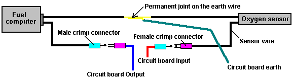
When set up like this, the male connector furthest on the left could be plugged into the female connector furthest on the right and the circuit board removed. Be sure to insulate the sensor and fuel computer plug/socket connections to make quite sure that neither of them can short-circuit to any part of the body. There is no need to insulate the earth connection as it is already connected to the body of the vehicle. Although not shown in the diagram, you could also put a male and female crimp connector pair on the earth cable. If your sensor has only one wire coming from it, then you best earth connection is to a solder-tag connector placed under a bolt on the engine. If you do that, be sure to clean all grease, dirt, rust, etc. off the underside of the bolt head and the area around the bolt hole. Push a paper towel into the bolt hole before doing this to make sure that no unwanted material ends up in the bolt hole and use wet-and-dry paper to really clean the surfaces. The objective here is to make sure that there is a very good electrical connection with shiny metal faces clamped firmly together.
Installing the Controller
Now, install the circuit board in the vehicle. For the 12 volt supply, find a connection which is switched on and off by the vehicle’s ignition switch. Don’t drive the car yet, do this test in the driveway. With the front panel switch in it’s “Off” position, start the car and check that it runs normally. Set the front panel rotary switch to the Richest position (connected to the IC’s Pin 10) and switch the circuit board toggle switch to it’s “On” position. The car is now running with a modified oxygen sensor signal although the mixture is still the same. The vehicle performance should be completely normal. Drive the vehicle with this setting for a while to prove that the system is working reliably before changing to any of the lower settings. When you are satisfied that everything is in order, try the next leanest setting on the rotary switch and see how it runs.
It is important that there should be no hesitation in the engine performance and no knocking or “pinking” as that is an indication that the mix is too lean and the engine is liable to overheat. This circuit is intended for use with an electrolyser, so your electrolyser should be set up and working for these tests. The electrolyser will tend to make the engine run cooler and offset any tendency towards overheating.
Building the Circuit Board
Although the above information has been presented as if the board has already been built, the actual construction details have been left until now, so that you will already have an understanding of what the circuit is intended to do and how it is used.
It is likely that you will know somebody (neighbour, friend, relative,...) who has the necessary equipment and skills. If so, borrow the equipment, or better still, recruit the person to help with the construction. It is very likely that anybody owning the equipment would be very interested in your project and more than willing to help out.
However, the rest of this document will be written on the assumption that you cannot find anybody to help and have had to buy all of the necessary equipment. This project is not difficult to build, so you will almost certainly be successful straight off.
The tools which you will need, are:
1. A soldering iron with a fine conical tapering tip (probably 15 watts power rating)
2. Some “Multicore” resin solder. This is special solder for electronics construction work and is quite different from plumber’s solder which is not suitable for this job.
3. A pair of long-nosed pliers (for holding component wires when soldering them in place)
4. Something for cutting and cleaning wires and stripping off insulation coverings. I personally prefer a pair of “nail” scissors for this job. Others prefer a pair of wire cutters and some sandpaper. You get whatever you feel would be the best tool for doing these tasks.
5. A 1/8 inch (3 mm) drill bit (for making bolt holes in the stripboard and for breaking the copper strips where needed) and a 3/8 inch (9 mm) drill and bit for mounting the switches on the plastic box.
6. A coping-saw or similar small saw for cutting the rotary switch shaft to the optimum length.
7. A small screwdriver (for tightening knob grub screws).
8. A crimping tool and some crimp connectors.
9. A multimeter (preferably a digital one) with a DC voltage measuring range of 0 to 15 volts or so.
10. (Optional) a magnifying glass of x4 or higher magnification (for very close examination of the soldering)
Soldering
Many electronic components can be damaged by the high temperatures they are subjected to when being soldered in place. I personally prefer to use a pair of long-nosed pliers to grip the component leads on the upper side of the board while making the solder joint on the underside of the board. The heat running up the component lead then gets diverted into the large volume of metal in the pair of pliers and the component is protected from excessive heat. On the same principle, I always use an Integrated Circuit socket when soldering a circuit board, that way, the heat has dissipated fully before the IC is plugged into the socket. It also has the advantage that the IC can be replaced without any difficulty should it become damaged.
If you are using CMOS integrated circuits in any construction, you need to avoid static electricity. Very high levels of voltage build up on your clothes through brushing against objects. This voltage is in the thousands of volts range. It can supply so little current that it does not bother you and you probably do not notice it. CMOS devices operate on such low amounts of current that they can very easily be damaged by your static electricity. Computer hardware professionals wear an earthing lead strapped to their wrists when handling CMOS circuitry. There is no need for you to go that far. CMOS devices are supplied with their leads embedded in a conducting material. Leave them in the material until you are ready to plug them into the circuit and then only hold the plastic body of the case and do not touch any of the pins. Once in place in the circuit, the circuit components will prevent the build up of static charges on the chip.
Soldering is an easily-acquired skill. Multi-cored solder is used for electronic circuit soldering. This solder wire has flux resin contained within it and when melted on a metal surface, the flux removes the oxide layer on the metal, allowing a proper electrical and mechanical joint to be made. Consequently, it is important that the solder is placed on the joint area and the soldering iron placed on it when it is already in position. If this is done, the flux can clean the joint area and the joint will be good. If the solder is placed on the soldering iron and then the iron moved to the joint, the flux will have burnt away before the joint area is reached and the resulting joint will not be good.
A good solder joint will have a smooth shiny surface and pulling any wire going into the joint will have no effect as the wire is now solidly incorporated into the joint. Making a good solder joint takes about half a second and certainly not more than one second. You want to remove the soldering iron from the joint before an excessive amount of heat is run into the joint. It is recommended that a good mechanical joint be made before soldering when connecting a wire to some form of terminal (this is often not possible).
The technique which I use, is to stand the solder up on the workbench and bend the end so that it is sloping downwards towards me. The lead of the component to be soldered is placed in the hole in the stripboard and gripped just above the board with long-nosed pliers. The board is turned upside down and the left thumb used to clamp the board against the pliers. The board and pliers are then moved underneath the solder and positioned so that the solder lies on the copper strip, touching the component lead. The right hand is now used to place the soldering iron briefly on the solder. This melts the solder on the joint, allowing the flux to clean the area and producing a good joint. After the joint is made, the board is still held with the pliers until the joint has cooled down.
Nowadays, the holes in the stripboard are only 1/10 inch (2.5 mm) apart and so the gaps between adjacent copper strips is very small indeed. If you solder carefully, there should be no problem. However, I would recommend that when the circuit board is completed, that you use a magnifying glass to examine the strip side of the board to make quite sure that everything is perfectly ok and that solder does not bridge between the copper strips anywhere. Before powering up the circuit, double-check that all of the breaks in the copper strips have been made correctly. Here is a possible layout for the components on the stripboard:
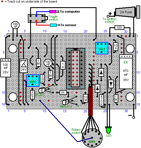
If this board is turned over horizontally, the underside will look like this:
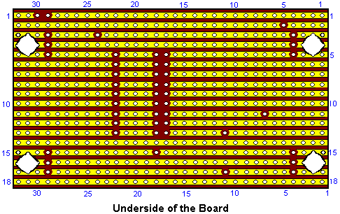
This shows where the breaks in the copper strips need to be made using a 1/8 inch (3 mm) drill bit.
To construct this circuit, cut a piece of stripboard which has 18 strips, each with 32 holes. That is a board size of about two inches (50 mm) by just over three inches (85 mm). Mount the components on the board, working from one end as the installation is easier if you have a clear board to work across. If you are right-handed, then start at the left hand side of the board and work towards the right, installing all components as you go. If you are left-handed, then mount the components starting with the right hand side of the board and working towards the left hand side.
Having said that, it is probably easier if you put all of the wire jumpers in place as the first step. The best wire for this is solid core wire of the type used in telephone wiring, as it is easy to cut, easy to remove the insulation and it lies flat on the board, clear of all of the other holes. So, start with the wire jumpers and then install the electronic components working across the board.
![]()
The jumper wires lie flat on the board, and like the other components, have about 2 mm of clean wire projecting through the copper strip before the solder joint is made.
The wires coming off the board should be of the type which have several thin wires inside the insulation, as these are more flexible and withstand the vibration of a vehicle in motion, better than solid core wire. If you have just one reel of wire, then be sure to label the far end of each piece mounted on the board, the moment you have soldered it in place. These labels will help avoid errors when mounting in the case, if you do not have different coloured wires.
The completed circuit board can be mounted in a small plastic box of the type which has a lid held in place by screws. It may be convenient to screw or bolt the case to the underside of the dashboard and then screw the lid in place, covering the mounting screws:
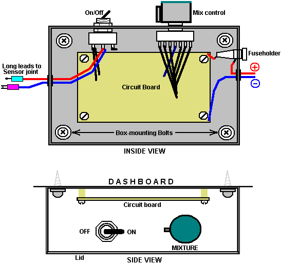
The components in this circuit are not critical and any near-match alternatives can be used. In the event that the MPSA14 Darlington-pair transistor is not available, then two general-purpose high-gain silicon transistors like the BC109 or 2N2222A can be substituted. Just connect them like this:
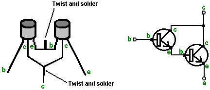
The emitter of the first transistor is connected to base of the second and the two collectors are connected together. If the transistors have metal cases, then make sure the emitter/base connection cannot touch either case as the cases are often connected internally to the collectors. If each transistor has a gain of only 200, then the pair will have a combined gain of 40,000 times. That means that the base current need only be 40,000 times less than the collector current of the second transistor.
The BC327 transistor can be replaced by almost any other silicon PNP transistor in this circuit as the gain does not need to be great and the power rating is very small. The following is a list of the main electronic components needed for the construction of this circuit as described here. There are several suppliers who are able to supply all of these components and the most suitable depends on where you are located. If there is any difficulty, try an internet search, and if that fails, ask for help in one or more of the Yahoo enthusiast groups such as ‘watercar’, ‘hydroxy’ or any of the electronics Groups.
|
Component |
Qty. |
US Supplier |
Code |
|
Black plastic box with lid, size about 4” x 3” x
2” |
1 |
Radio Shack |
270-1803 |
|
Stripboard: 18 strips, 32 holes |
1 |
Electronix Express |
0302PB16 |
|
Double Pole Double Throw toggle switch |
1 |
Radio Shack |
275-636 |
|
Fuse holder, panel mounting, 1.25” |
1 |
Radio Shack |
270-364 |
|
Fuse, 2 amp slow-blow 1.25” |
1 |
Radio Shack |
270-1262 ?? (3 A) |
|
Rotary wafer switch, 12-way single pole |
1 |
Electronix Express |
17ROT1-12 |
|
Knob for the rotary switch |
1 |
Radio Shack |
274-424 |
|
LED, any colour, 5 mm diameter |
1 |
Radio Shack |
276-041 |
|
IC socket, 18 pin DIL |
1 |
Radio Shack |
276-1992 |
|
Miniature preset resistor, 10K linear |
2 |
Radio Shack |
271-282 |
|
LM3914 LED bar driver Integrated Circuit |
1 |
Electronix Express |
LM3914 |
|
BC327 PNP transistor |
1 |
Electronix Express |
2N2905 |
|
MPSA14 Darlington pair transistor |
1 |
Electronix Express |
MPSA14 |
|
1N4007 Diode or equivalent |
3 |
Radio Shack |
276-1103 (2 pack) |
|
BZX85C zener diode, 24 volt version |
1 |
Electronix Express |
1N5359 |
|
470 microfarad, 35 volt (or higher) axial lead
aluminium foil electrolytic capacitor |
1 |
Radio Shack |
272-1018 |
|
100 microfarad, 35 volt (or higher) axial lead aluminium
foil electrolytic capacitor |
1 |
Radio Shack |
272-1016 |
|
100 nF (0.1 microfarad) ceramic disc capacitor |
2 |
Radio Shack |
272-135 (2 pack) |
|
10 megohm 1/4 watt carbon resistor (Bands: Brown,Black,Blue) |
1 |
Radio Shack |
271-1365 (5 pack) |
|
1 megohm 1/4 watt carbon resistor (Bands: Brown,Black,Green) |
3 |
Radio Shack |
271-1356 (5 pack) |
|
470K 1/4 watt carbon resistor (Bands: Yellow,Purple,Yellow) |
1 of 1 |
(Radio Shack) Radio Shack |
use two 1M in parallel or 271-1133 (5 pack 1/2 watt) |
|
10K 1/4 watt carbon resistor (Bands: Brown,Black, |
1 |
Radio Shack |
271-1335 (5 pack) |
|
2.7K 1/4 watt carbon resistor (Bands: Red,Purple,Red) |
1 |
Radio Shack |
271-1328 (5 pack) [use 3.3K] |
|
1K 1/4 watt carbon resistor (Bands: Brown,Black,Red) |
2 |
Radio Shack |
271-1321 (5 pack) |
|
100 ohm 1/4 watt carbon resistor (Bands: Brown,Black,Brown) |
1 |
Radio Shack |
271-1311 (5 pack) |
|
Connecting wire: stranded and solid core |
|
Local supplier |
|
Electronix Express
http://www.elexp.com/index.htm
Radio Shack
http://www.radioshack.com/home/index.jsp
And for a
|
Component |
Qty. |
European Supplier |
Code |
|
Black
plastic box with lid, size about 4” x 3” x 2” |
1 |
ESR |
400-555 |
|
Stripboard:
18 strips, 32 holes |
1 |
ESR |
335-010 |
|
Double
Pole Double Throw toggle switch |
1 |
ESR |
218-028 |
|
Fuse
holder, panel mounting 31 mm |
1 |
ESR |
187-115 |
|
Fuse,
2 amp 31 mm |
1 |
ESR |
190-220 |
|
Rotary
wafer switch, 12-way single pole |
1 |
ESR |
210-012 |
|
Knob
for the rotary switch |
1 |
ESR |
060-22X |
|
LED,
any colour, 5 mm diameter |
1 |
ESR |
711-540 |
|
IC
socket, 18 pin DIL |
1 |
ESR |
110-180 |
|
Miniature
preset resistor, 10K linear |
2 |
ESR |
998-310 |
|
LM3914
LED bar driver Integrated Circuit |
1 |
ESR |
LM3914 |
|
BC327
PNP transistor |
1 |
ESR |
BC327 |
|
MPSA14
Darlington pair transistor |
1 |
ESR |
MPSA13 |
|
1N4007
Diode or equivalent |
3 |
ESR |
1N4007 |
|
BZX85C
zener diode, 24 volt version |
1 |
ESR |
726-240 |
|
470
microfarad, 35 volt (or higher) axial lead aluminium foil electrolytic
capacitor |
1 |
ESR |
810-104 |
|
100
microfarad, 35 volt (or higher) axial lead aluminium foil electrolytic
capacitor |
1 |
ESR |
810-096 |
|
100
nF (0.1 microfarad) ceramic disc capacitor |
2 |
ESR |
871-061 |
|
10
megohm 1/4 watt carbon resistor (Bands:
Brown,Black,Blue) |
1 |
ESR |
906-610 |
|
1
megohm 1/4 watt carbon resistor (Bands:
Brown,Black,Green) |
3 |
ESR |
906-510 |
|
470K
1/4 watt carbon resistor (Bands:
Yellow,Purple,Yellow) |
1 |
ESR |
906-447 |
|
10K
1/4 watt carbon resistor (Bands:
Brown,Black, |
1 |
ESR |
906-310 |
|
2.7K
1/4 watt carbon resistor (Bands:
Red,Purple,Red) |
1 |
ESR |
906-227 |
|
1K
1/4 watt carbon resistor (Bands:
Brown,Black,Red) |
2 |
ESR |
906-210 |
|
100
ohm 1/4 watt carbon resistor (Bands:
Brown,Black,Brown) |
1 |
ESR |
906-110 |
|
Reel
of multi-strand connecting wire 6 amp Red |
1 |
ESR |
054-112 |
|
Reel
of multi-strand connecting wire 6 amp Blue |
1 |
ESR |
054-116 |
|
Reel
of solid core (or local phone wire) |
1 |
ESR |
055-111 |
ESR http://www.esr.co.uk Tel: 01912 514 363
While the components listed above are the parts needed
to construct the electronics board, the following items may be needed in
addition when testing and installing the board in a vehicle:
|
Component |
Use |
|
Rubber or plastic grommets |
To protect wires from rubbing against the edges of
the holes in the box |
|
Crimp “bullet” connectors |
Male and female, one pair for each sensor wire
cut |
|
Mounting bolts, nuts and spacers |
To hold the circuit board securely, clear of the
box. |
|
Double-sided adhesive tape |
For mounting the box on the dash. Alternatively, hardware items for this. |
|
Fuse-box connector |
For connecting to the fuse box to give an
ignition-switched 12V supply |
|
10K resistor and 1K Linear variable resistor |
For bench testing with voltages of up to 1 volt,
if these components are not already to hand |
|
Multimeter |
For general checking of voltages, continuity,
etc. |
I should like to express my sincere thanks to the various members of the ‘watercar’ Group who provided the technical information and patient support which made this document possible.
An alternative: As the signal coming from the oxygen sensor to the vehicle’s ECU fuel computer needs to be raised slightly to allow for the much cleaner exhaust produced when a booster is being used, an alternative solution has been suggested and tested. The idea is to add a small, adjustable voltage to the signal already coming from the oxygen sensor. This voltage can be from a single ‘dry-cell’ battery and adjusted with a variable resistor:
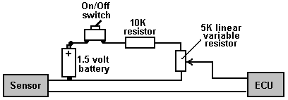
The circuit shown here allows a voltage anywhere from zero to 0.5 volts to be added to the oxygen sensor signal. This must not be done unless a booster is running. Using it without a booster is liable to lead to engine overheating and possible valve damage. This, of course, applies to the previous oxygen sensor signal adjusting circuit as well.
Please Note: This document has been prepared for information purposes
only and must not be construed as an encouragement to build any new device nor
to adapt any existing device. If you
undertake any kind of construction work, then you do so entirely at your own risk. You, and only you, are responsible for your
own actions. This document must not be
seen as an endorsement of this kind of adaptation nor as providing any kind of
guarantee that an adaptation of this kind would work for you personally. This document merely describes what has been
achieved by other people and you must not consider it as being a foolproof
blueprint for replication by anyone else.
Suggested Design Features
for High-power DC Electrolysers
The objective of this document is to present the relevant facts involved in DC electrolysis and provide practical suggestions for the physical construction, preparation and use of such devices.
Disclaimer
The contents of this document are presented for information
purposes only. The author, Patrick J.
Kelly does not recommend that anyone actually build any device based on this
information and should anyone do so against his wishes, then it must be clearly
understood that no responsibility attaches to Patrick J. Kelly as a result of
those actions. By way of example, should
somebody decide to construct an electrolyser based on this information and then
drop the electrolyser on his toe, then Patrick J. Kelly is in no way liable for
any resulting injury or damage to the electrolyser.
Background:
The very famous Michael Faraday who performed meticulous experimentation, investigated electrolysis and determined what current was needed to convert any given quantity of water into hydrogen and oxygen gasses. Teachers of science, quote Michael’s results as being the final word on DC electrolysis.
In the last
few years, Bob Boyce of the
Bob Boyce had a different objective during his investigations, namely to determine if there was any way to raise the gas production per amp of current. His first step was to test various types of metal for the electrodes. Laboratory investigations tend to pick platinum for electrode use, but in fact, that is the worst possible metal to use as it acts as a catalyst to recombine hydrogen and oxygen gasses, and so has an in-built opposition to electrolysis. After much testing, 317L-grade was found to be an excellent choice, but due to its limited availability and high cost, 316L-grade is generally used instead.
The loss factors involved in electrolysis were then examined by following the path of the current. These are:
1. Resistance to current flow through the metal electrodes, (typically in the form of plates).
2. Resistance to flow between the electrode and the electrolyte.
3. Resistance to flow through the electrolyte itself.
These electrical losses produce heat, which in limited amounts is not a problem other than through wasted energy, but if left uncontrolled, causes considerable problems, namely the production of steam and hot water vapour which dilute the hydroxy gas and reduce the energy content of the output, and in extreme cases, melting or weakening the case material. Examining each of these, Bob found:
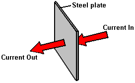
1. Resistance to current flow through the metal plates is something which can’t be overcome easily and economically, and so has to be accepted as an overhead. Generally speaking, the heating from this source is low and not a matter of major concern.
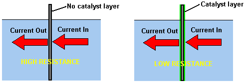
2. Resistance to flow between the electrode and the electrolyte is an entirely different matter, and major advances can be made in this area. After extensive testing, Bob discovered that a major improvement can be made if a catalytic layer is developed on the active plate surface. Details of how this is done are provided below.
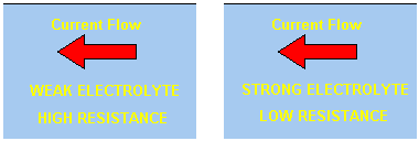
3. Resistance to flow through the electrolyte itself can be minimised by using the best catalyst at its optimum concentration, and controlling the current flow by using an electronic circuit. The options here are the use of a Pulse-Width Modulator (or “PWM”) circuit or a Constant-current Circuit. A PWM circuit switches the current off for any chosen percentage of the time. This reduces the average current flowing through the electrolyte and so controls the gas output rate. This circuit is manually set and adjusted as necessary. The Constant-current circuit maintains any chosen current through the electrolyte automatically. Another factor is the distance which the current has to flow through the electrolyte - the greater the distance, the greater the resistance. Reducing the inter-plate gap to a minimum improves the efficiency. However, practical factors come into play here as bubbles have to have sufficient space to escape between the plates, and in a compact series-connected electrolyser, the electrolyte volume between successive plates is severely restricted if the plates are over close to each other. Bob’s chosen compromise spacing is 3 mm. or one eighth of an inch.
These factors allow a doubling of Faraday’s results, or to put it another way, give Faraday’s gas output for less than half the current which he found it necessary to use. The best catalyst known at this time is potassium hydroxide or KOH. This is 20% more efficient in use than the next most suitable catalyse sodium hydroxide or NaOH. It is quite possible that a better catalyst may be discovered in the future, which would lower the current requirement further for any required gas output rate. The plate area is important for long electrode life and a plate area of at least 4 square inches per amp of current will give extended plate life. There is an advantage in having the plates wider than they are tall as this provides more electrolyte surface area
The creation of the very important catalyst layer on the working faces of the electrode plates is as follows:
The first step is to treat both surfaces of every plate to encourage gas bubbles to break away from the surface of the plate. This could be done by grit blasting, but if that method is chosen, great care must be taken that the grit used does not contaminate the plates. Stainless steel plates are not cheap and if you get grit blasting wrong, then the plates will be useless as far as electrolysis is concerned. A safe method which Bob much prefers is to score the plate surface with coarse sandpaper. This is done in two different directions to produce a cross-hatch pattern. This produces microscopic sharp peaks and valleys on the surface of the plate and those sharp points and ridges are ideal for helping bubbles to form and break free of the plate.
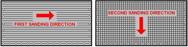
Bob uses a 6-inch x 48-inch belt sander which is great for preparing the plates and he uses it all the time now with 60 or 80 grit. Always wear rubber gloves when handling the plates to avoid getting finger marks on the plates. Wearing these gloves is very important as the plates must be kept as clean and as grease-free as possible, ready for the next stages of their preparation.
Any particles created by the sanding process should now be washed off the plates. This can be done with clean tap water (not city water though, due to all the chlorine and other chemicals added), but only distilled water is used for the final rinse.
The next step in the preparation process is to make up a weak solution of sodium hydroxide. This is done by adding small amounts of the sodium hydroxide to water held in a container. The container must not be glass as most glass containers are made from glass of insufficient quality to allow mixing of electrolyte in them. Sodium hydroxide (“caustic soda” often sold as drain cleaner) is always used for plate cleansing.
While both Potassium Hydroxide (KOH) and Sodium Hydroxide (NaOH) are excellent materials, they both are highly caustic and so need to be treated with care. In the following section, the mixing of KOH is described, but the same precautions also apply when mixing NaOH. So be very methodical and careful when making up a solution of either:
Always store the hydroxide in a sturdy air-tight container which is clearly labelled "DANGER! - Potassium Hydroxide". Keep the container in a safe place, where it can’t be reached by children, pets or people who won't take any notice of the label. If your supply of KOH is delivered in a strong plastic bag, then once you open the bag, you should transfer all its contents to sturdy, air-tight, plastic storage containers, which you can open and close without risking spilling the contents. Hardware stores sell large plastic buckets with air tight lids that can be used for this purpose.
When working with dry hydroxide flakes or granules, wear safety goggles, rubber gloves, a long sleeved shirt, socks and long trousers. Also, don’t wear your favourite clothes as a hydroxide solution is not the best thing to get on clothes. It is also good practice to wear a face mask which covers your mouth and nose. If you are mixing solid hydroxide with water, always add the hydroxide to the water, and not the other way round, and use a plastic container for the mixing, preferably one which has double the capacity of the finished mixture. The mixing should be done in a well-ventilated area which is not draughty as air currents can blow the dry hydroxide around.
When mixing the electrolyte, never use warm water. The water should be cool because the chemical reaction between the water and the hydroxide generates a good deal of heat. If possible, place the mixing container in a larger container filled with cold water, as that will help to keep the temperature down, and if your mixture should “boil over” it will contain the spillage. Add only a small amount of hydroxide at a time, stirring continuously, and if you stop stirring for any reason, put the lids back on all containers.
If, in spite of all precautions, you get some hydroxide solution on your skin, wash it off with plenty of running cold water and apply some vinegar to the skin. Vinegar is acidic, and will help balance out the alkalinity of the hydroxide. You can use lemon juice if you don't have vinegar to hand - but it is always recommended to keep a bottle of vinegar handy.
Plate Cleansing:
Plate cleansing is always done with NaOH. Prepare a 5% to 10% (by weight) NaOH solution and let it cool down. A 5% solution ‘by weight’ is 50 grams of NaOH in 950 cc of water. A 10% solution ‘by weight’ is 100 grams of NaOH in 900 cc of water. As mentioned before, never handle the plates with your bare hands, but always use clean rubber gloves. Put the sanded and rinsed plates into the slots in the electrolyser case. Fill the electrolyser with the NaOH solution until the plates are just covered.
A voltage is now applied across the whole set of plates by attaching the leads to the outermost two plates. This voltage should be at least 2 volts per cell, but it should not exceed 2.5 volts per cell. Maintain this voltage across the set of plates for several hours at a time. The current is likely to be 4 amps or more. As this process continues, the boiling action will loosen particles from the pores and surfaces of the metal. This process produces hydroxy gas, so it is very important that the gas is not allowed to collect anywhere indoors (such as on ceilings).
After several hours, disconnect the electrical supply and pour the electrolyte solution into a container. Rinse out the cells thoroughly with distilled water. Filter the dilute NaOH solution through paper towels or coffee filters to remove the particles. Pour the dilute solution back into the electrolyser and repeat this cleaning process. You may have to repeat the electrolysis and rinsing process many times before the plates stop putting out particles into the solution. If you wish, you can use a new NaOH solution each time you cleanse, but you can go through a lot of solution just in this cleaning stage if you choose to do it that way. When cleansing is finished (typically, after three days), do a final rinse with clean distilled water. It is very important that during cleansing, during conditioning and during use, that the polarity of the electrical power is always the same. In other words, don’t swap the battery connections over as that destroys all the preparation work and requires the cleansing and conditioning processes to be carried out all over again.
Plate Conditioning:
Using the same concentration of NaOH solution as in cleansing, fill the electrolyser with the dilute solution up to 1/2" below the tops of the plates. Do not overfill the cells. Apply about 2 volts per cell and allow the unit to run. Remember that very good ventilation is essential during this process. The cells may overflow, but this is ok for now. As water is consumed, the levels will drop. Once the cells stabilise with the liquid level at the plate tops or just below, monitor the current draw. If the current draw is fairly stable, continue with this conditioning phase continuously for two to three days, adding just enough distilled water to replace what is consumed. If the solution changes colour or develops a layer of crud on the surface of the electrolyte, then the cell stack needs more cleansing stages. Do not allow the cells to overfill and overflow at this point. After two to three days of run time, pour out the dilute NaOH solution and rinse out the electrolyser thoroughly with distilled water. When the plates are conditioned, bubbles will not stick to them but will break away freely. The catalytic layer causes the plates to take on a bronze colouring.
Cell Operation:
Mix up a full-strength 28% ‘by weight’ solution of potassium hydroxide, that is 280 grams of KOH added to 720 cc of water. Fill the electrolyser of this design to about an 8-inch depth, which leaves some 4-inches of freeboard to help contain splashes caused by the very high rate of electrolysis. The DC voltage applied to the electrolyser will be about 2 volts per cell, so this 150-cell electrolyser will have about 300 volts applied to it. This voltage is generated by rectifying the 220 volt AC mains.
Troubleshooting:
1. Abnormally low current is caused by improper plate preparation or severe contamination. Take the plates out of the electrolyser and start over again from plate preparation.
2. Abnormally high current is caused by high leakages between cells. This will require the re-building or tightening up of the plate array case.
3. If current starts high and then drops off, this means that the plates are contaminated. Take the plates out of the electrolyser and start over again from plate preparation.
4. Any time there is uneven voltage distribution between cells in a series cell, it means that there is either a large variation in surface preparation from cell to cell, or there is ion leakage between the cells. Surface preparation issues will tend to show up as one or more cells having higher voltage, but not in any specific order. Ion leakage (also called bypass leakage) shows up as uneven voltage distribution, typically higher at the end cells.
Voltage distribution should be even, and within a few hundredths of a
volt. Variation of tenths of a volt
means that there is a major problem.
Make sure that your plate array is clamped tightly. Check for any place at all for liquid to
flow, as this will allow ion leakage to bypass your central "floating"
plates.
The Gas Produced:
Schoolteachers will tell you that the electrolysis of water produces hydrogen gas (H2) and oxygen gas (O2). While this is true, it is only part of the story. Water dissolves things so well that “pure” water really does not exist. Rain falling from the sky will have absorbed atmospheric gasses on its way down and is no longer “pure” by the time it reaches the ground.
As it flows along the surface of the ground and through the fabric of the landscape, it absorbs minerals of all descriptions, and as it flows down streams the splashing causes it to absorb more atmospheric gasses (which is just as well for the fish living in that water). If it reaches a water treatment plant, it will be injected with chlorine to kill the bacteria in it, and possibly fluorine to “improve the teeth” of the people who drink it.
Tap water is an electrolyte, but one where you don’t know what is in it. Tap water samples taken in different towns will contain a very different mix of additives while samples taken in different countries will have even greater differences between them.
Most people would be inclined to say “who cares?” but this is an important matter when electrolysis of water is being considered. If you use tap water for electrolysis, then as the electrolysis proceeds, the “pure” water is removed as a mixture of hydrogen gas and oxygen gas. This releases the air dissolved in the water, so mixed with the hydroxy gas is an unknown amount of air which is 78% Nitrogen. The dissolved solids and any solids in suspension in the water, get left behind and they collect in the bottom of the electrolyser. As a large proportion of naturally occurring landscape has iron salts in it, a good deal of these may collect in the bottom of the electrolyser. One common element is iron oxide, commonly known as “rust” and although it is not the best, it is a conductor of electricity, so it has been know for electrolyser plates to get shorted out by a conductive layer building up between the plates. This short-circuits the plates, cuts the gas production and generates excess heat - generally, a condition to be avoided.
For this reason, it is strongly recommended that the working KOH electrolyte be made up with either distilled water or de-ionised water, and the water used for replacing the water lost through electrolysis also be distilled or de-ionised water. It should be realised that even when using distilled water, the hydroxy gas produced will also have dissolved air in it.
Supplying Water:
Surprisingly, supplying water to replace that which has been converted to hydroxy gas, is not a simple task. Firstly, there is a 5 psi gas pressure inside the electrolyser and so a one-way valve needs to be placed in the water supply line in order to prevent the gas pressure pushing the water out and letting gas escape through the water supply apparatus.
In addition, there is considerable difficulty in knowing when water is needed and how much should be introduced into the electrolyser and added to that is the difficulty in adding exactly the same amount to each of the 150 cells which are only 3 mm wide. While it is not essential that each of the 150 cells has exactly the same electrolyte level, it is very important that the added water is exactly the same amount for each cell, otherwise the cell electrolyte levels will get progressively out of step. There is a degree of automatic balancing of the levels in that a fuller cell is likely to produce slightly more gas and so use slightly more water, thus balancing the levels, but this slight difference cannot be relied on to offset unevenly supplied water.
Recently, Ed Holdgate and Tom Thayer designed a double-pipe arrangement for the water supply and it is said to work adequately, so using a slightly longer version of their design may well be a satisfactory solution. However, this part of the design should be considered as an area for careful checking under working conditions and possible future modification to provide an enhanced operation. Overall the operation would be:
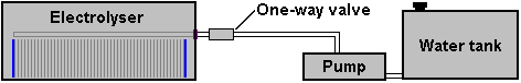
The problem of assessing the correct electrolyte level is made more difficult by the severe bubbling caused by the electrolysis which will have the surface of the liquid in constant vertical motion. Optical sensing is not likely to be effective. Overall weight of the electrolyser is a possible guide but is an unusual approach to the problem and so is probably not a first choice. The normal approach is to use two wires as a sensor as electrical conduction will take place when they are connected by electrolyte. However, this environment with low conductivity electrolyte being splashed all over the place makes for the possibility of somewhat erratic operation, but in spite of that, it is probably the best method.
For this style of sensor a pair of stiff stainless steel wires insulated in shrink wrap or a narrow plastic tube is run down between two of the central plates and positioned on opposite sides of the gap as shown here:
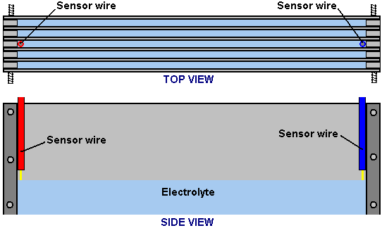
The electronic circuit being fed by this sensor will have a delay of several seconds so that bubbling does not cause false triggering of the water feed. In other words, the electronic sensor circuit will only power the water pump if the electrical connection through the electrolyte between the two sensor wires is lost for several consecutive seconds.
Physical Construction:
To a casual glance, the physical construction of a high-performance electrolyser looks simple but the reality is that it is anything but that. A low-performance electrolyser can have sloppy construction. There are some difficulties which have to be overcome in order to get a top performance.
1. It is vital to avoid having any kind of bypass path for the electrical current which would allow it to flow from the negative terminal to the positive terminal without passing through the electrode plates. While this sounds easy to achieve, it is not actually so.
2. It is important to extract the hydroxy gas from the electrolyser while leaving all of the electrolyte behind. This sounds obvious, but in high gas volume operations it is not a trivial thing to achieve.
3. It is important that the temperature of the electrolyser does not rise to an unacceptable level which could cause damage to the electrolyser case or fittings, or which could generate steam or excess water vapour which would dilute the hydroxy gas and lower the efficiency of the fuel.
4. It is important that there is no possibility of a spark being generated inside the electrolyser by a loose electrical connection.
The Bob Boyce electrolyser design is a very convenient construction for the user but it calls for precision construction to 0.0003” accuracy which is well outside the scope of amateur builders. A DC electrolysis unit does not have the need for this degree of accuracy and so I would suggest an adaptation of Bob Boyce’s style of construction for small boosters. This builds up an array of plates clamped together with threaded rods and held apart by U-shaped insulating spacers.
The spacers need to be made of a material which is slightly flexible so that when clamped between two steel plates it forms a completely watertight seal. The material also need to be wholly resistant to the strongly caustic KOH solution being used as an electrolyte.
This plate array can be a self-contained unit with the end plates reinforced against flexing with either a thick piece of acrylic plastic or by making them out of thick stainless steel. All metal components inside the electrolyser need to be made of the same grade of metal, otherwise galvanic erosion will take place as the whole inside of the electrolyser will have a damp conductive gas in it. The arrangement could be like this:
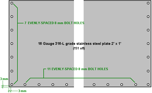
Here an evenly spaced ring of bolt holes to take 8 mm bolts is drilled around three edges of each of the 151 plates. The holes will be 8.5 mm in diameter if 8 mm threaded plastic rods are used. The spacing of the holes is just under two inches as 3 mm clearance is needed at the edges and the stainless steel plates supplied may not be exactly 2 feet by 1 foot but one sixteenth of a metric size plate. The exact plate size is not critical nor is the exact spacing of the threaded rods.
It may be preferred to use stainless steel threaded rods rather than the less robust plastic rods, in which case the hole diameter will be increased, probably to 10 mm or the threaded rod diameter reduced to 6 mm as the whole length of the rod running through the plates will be encased in plastic sleeving in order to prevent electrical contact between the plates and the rods as shown here:
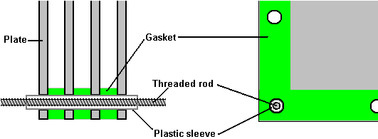
The 150 gaskets match the edges of the plates and have a width of 6 mm greater than the diameter of the hole drilled for the rods which clamp the plate array together:
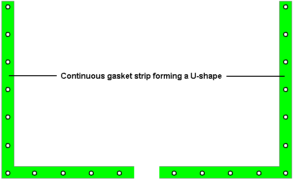
Applying this style of construction produces a compact plate array with the desired plate spacing, low accuracy components which can be obtained quite readily. The electrical connections to the end plates are TIG welded straps as shown here:
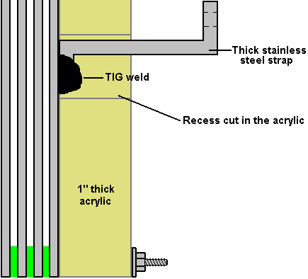
A rectangular hole is cut through the acrylic backing plate to allow a TIG welded strap of thick stainless steel to project through it and provide a good electrical connection. The strap is bolted through the outer case using a stainless steel bolt and a gasket to ensure that it will not allow gas to escape.
An outer case of thick acrylic can be used to house the plates, water-supply pipe, etc. and contain the hydroxy gas, forcing it to enter the gas supply pipe feed to the generator engine. The outer case is never made from any kind of metal no matter how attractive the idea seems. While the possibility of an explosion inside the electrolyser is most unlikely, safety is the number one priority and if an explosion were to take place inside a metal-cased electrolyser, then it would act like a landmine, scattering lethal shrapnel in every direction. Pop-off lids, and shatter discs seem attractive options to many people, but these are useless with hydroxy gas which contains the ideal proportions of hydrogen fuel and oxygen, which when ignited produce a shock-wave so fast that these devices do not have time to operate. An electrolyser of the size and proportions suggested here contains far too much hydroxy gas to be contained by any kind of metal casing.
Baffle System:
It must be assumed that the high rate of gas production will cause splashing and even with having some four inches of plate above the surface of the electrolyser, that tiny droplets will be projected upwards above the plates. It is essential that these droplets are trapped and that any KOH vapour mixed with the hydroxy gas is removed before the gas is fed to the engine.
A set of baffles above the plates can be used to intercept any droplets and return them to the electrolyte again, and two bubblers can be used to wash any KOH vapour out of the hydroxy gas and protect both the engine and prevent a serious explosion in the unlikely event of a malfunction of the generator engine. The baffles can be made of acrylic and could be like this:
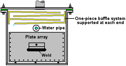
Ideally, the lower end of the lowest baffle plate is grooved so that there is a ridge on the underside of the baffle located just above each body of electrolyte so that any drips land directly where they should.
The Outer Case:
As this electrolyser design is built up from the separate self-contained components of the plate array, the water supply pipe pair and the baffle plate array, it is necessary to enclose these in an outer case as shown above. It could easily be thought that this case is of little consequence and so could be constructed from almost any material, but this is not so as the case has to be able to withstand prolonged exposure to strong KOH electrolyte and to be robust enough not to break if an attempt to pick it up off the floor.
A construction of this general size will have a substantial weight as it contains some 300 square feet of stainless steel sheet, plus more than three cubic feet of electrolyte weighing about 248 pounds or 113 Kg. So the plates and electrolyte will weigh about 1,000 pounds or 460 Kg. and therefore if it is intended that the electrolyser is to be picked up and moved, it will be necessary to place it on a pallet or use a steel plate under the case with angle irons at the corners and a central lifting point for a hoist.
Considering these facts, the case should be constructed from acrylic sheet 25 mm thick. Acrylic sheets can be connected together with a solvent which the supplier of the acrylic can provide. This does not ‘glue’ the sheets together but actually combines them into one integral piece with no join. Surprisingly, this actually calls for a high degree of precision in cutting the sheets which are to be joined together as the requirement is for a perfect mating of the two surfaces before the solvent is applied. It might be noted that Ed Holdgate who has high quality machine tools, years of experience and a high level of personal skill, sub-contracts the jointing of the acrylic components which go to make up a Bob Boyce electrolyser case.
Bubblers:
A fact which is easily overlooked is the sheer volume of gas coming off an electrolyser of this size. It is one thing to calculate the diameter of pipe needed to carry the gas flow, but another to realise that the same gas flow needs to pass continuously through a bubbler and the bubbler design has to accommodate that volume and yet ensure that all of the gas comes into intimate contact with the water.
Perhaps then the first step is to establish a suitable pipe size for the gas flow. At this point in time it is not known exactly what efficiency and performance can be expected from this particular design operating on 300 volts and 30 amps of current. It is probably safe to predict that the gas rate will not exceed 250 litres per minute which is 4.2 litres per second.
Passing through a standard 90 mm (3.5“) diameter pipe of 63 sq. cm. cross-sectional area that would require a flow rate of 66 cm. per second or just over two feet per second. While that is possible and 10 bar pipe of that diameter is available at £4.40 plus VAT per metre.
The next standard pipe size is 110 mm (4.3”) which has a cross-sectional area of 95 sq. cm. which would give a flow rate of 44 cm./sec. or just under 1.5 ft/sec. which is a perfectly reasonable rate of flow. The cost of that pipe in 10-bar rating is just over £6 plus VAT per metre.
The next standard pipe size is 160 mm (6.3“) which has a cross-sectional area of 201 sq. cm. which would give a flow rate of 21 cm./sec. or just under 0.8 ft/sec. and the cost of that pipe in 10-bar rating is just over £14.23 plus VAT per metre.
These figures indicate that cost is not a significant factor and while moving from a reasonably convenient 90 mm diameter pipe to the much less convenient 160 mm size more than halves the flow rate, there does not seem to be any reason to go over the 90 mm size. The actual gas pressure in the electrolyser will be held down to 5 psi (0.36 bar) as compressing hydroxy gas is not a particularly safe thing to do. Consideration should be given to using piping which is specifically constructed to carry hydrogen, but it seems unlikely that it would be readily available in the larger sizes needed.
So, basing the bubbler dimensions on a 90 mm diameter pipe, the bubbler arrangement might be like this:
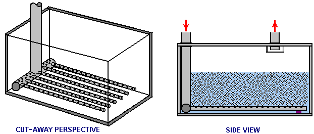
The objective being to ensure that there is a very large number of small bubbles streaming up through a considerable depth of water. The most suitable dimensions are a matter of opinion but as space is not an issue I would suggest the following:
The cross-sectional area of the inner diameter of the small diameter pipes laid on the bottom of the bubbler should exceed the cross-sectional area of the main incoming pipe. For clarity, the above diagram shows just six of these pipes but there is no reason why there should not be a much larger number. If there were just six pipes and an incoming pipe of diameter of 90 mm, then the small pipe diameter would be 18 mm internal diameter or greater.
It would also be good if the cross-sectional area of the holes drilled in these smaller pipes exceeded the cross-sectional area of the small pipe. As there should be a very large number of small holes, it is highly likely that it desirable target will be met quite easily.
I would suggest that the depth of water above the top of the small pipes be eight inches or 200 mm and that perhaps half of that depth be allowed between the water surface and the top of the container. The outlet pipe is shown with a baffle, but with stationary operation, constant flow and the dimensions suggested, it is unlikely that it will have any significant work to do.
The piping between the electrolyser and the bubbler, and between the first bubbler and the second one, should be kept as short as is reasonable.
Controlling Current Flow:
In a DC electrolyser such as this one, the gas flow rate is directly proportional to the current flowing through the electrolyte. The amount of gas per amp of current is highly dependent on the electrical efficiency of the construction (something which the casual onlooker will not see). It does no harm to stress again that the plate cleansing and conditioning are of major importance. It is very difficult for most people to be patient during the preparation stages as they are impatient to see their construction performing, but it is vitally important for that performance that the construction and preparation are carried out fully and without haste, as with high-quality painting, the finished quality depends to a major extent on the preparation work undertaken before the finishing coats are applied. So too with electrolysers, the output efficiency depends heavily on the quality of the preparation work.
However, as the current flow is the controlling factor in the rate of gas production, having a circuit which holds the current flow steady even if conditions such as temperature were to alter. It is, of course, vital to have safety devices which cut off the electrolyser if the generator stops running. The high-power, high-voltage, constant-current circuit prototype being proposed for this application is intending to use the oil pressure of the generator as an indication of engine shutdown. It is also proposed that a 5 psi pressure switch be used to cut the electrical power if the internal pressure rises above its design level. However, the pressure switch is liable to be ineffective in this instance as the potential rate of gas production is so high and the gas is fed into open air side of the air filter which will allow it to escape and that would be dangerous unless the air intake is fed from a pipe which connects to the open air, in which case, excess hydroxy gas would escape harmlessly into the open where it would quickly disperse and cease to be a danger.
The proposed electrical supply arrangement is then:
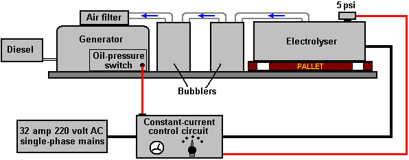
Here, the electronic control circuit is receiving input signals to indicate the performance of the generator and the electrolyser, allowing it to adjust the current accordingly. If it is not possible to connect to the oil pressure switch of the generator, then the constant-current control circuit can be made to operate by sensing the voltage produced by the generator and use that to detect the generator stopping.
Enhancements:
It has been remarked that high operating temperatures in the electrolyser are not welcome because of the production of steam and hot water vapour. In passing, the electrolyser could be placed in a water-cooled jacket or bath to keep the temperature down. This is not likely to be necessary as the electrolyser design is very efficient with two volts per cell, the best electrolyte and conditioned catalyst interface layers between the plates and the electrolyte.
Steam and hot water vapour are not wanted as they are not capable of expanding further and so they just take up space inside the engine cylinders, space which would much better be filled with a useful fuel like hydroxy gas. However, it is a very different matter if instead of steam a fine spray of water droplets is introduced instead. When combustion takes place inside the cylinder, the temperature rises suddenly and those water droplets convert instantly into flash-steam, creating increased pressure on the piston, raising the engine power and doing it without using any fuel at all. It also lowers the running temperature of the engine which is generally beneficial and tends to give longer engine life.
Producing fine water droplets is not particularly easy, but some aquarium outlets, pet shops and garden centres can supply a “pond fogger” which does exactly that at low cost and low input current. It is distinctly possible that feeding the output of one or more of these into the air entering the engine may give an improvement in performance and fuel economy.

The High-Power Devices of
Don Smith.
One of most impressive developers of free-energy devices is Don Smith who has produced many spectacular devices, generally with major power output. These are a result of his in-depth knowledge and understanding of the way that the environment works. Don says that his understanding comes from the work of Nikola Tesla as recorded in Thomas C. Martin's book "The Inventions, Researches, and Writings of Nikola Tesla" ISBN 0-7873-0582-0 available from http://www.healthresearchbooks.com and various other book companies. This book can be downloaded from http://www.free-energy-info.tuks.nl as a pdf file, but a paper copy is much better quality and easier to work from.
Don states that he repeated each of the experiments found in the book and that gave him his understanding of what he prefers to describe as the 'ambient background energy' which is called the 'zero-point energy field' elsewhere in this eBook. Don remarks that he has now advanced further than Tesla in this field, partly because of the devices now available to him and which were not available when Tesla was alive.
Don stresses two key points. Firstly, a dipole can cause a disturbance in the magnetic component of the 'ambient background' and that imbalance allows you to collect large amounts of electrical power, using capacitors and inductors (coils). Secondly, you can pick up as many powerful electrical outputs as you want from that one magnetic disturbance, without depleting the magnetic disturbance in any way. This allows massively more power output than the small power needed to create the magnetic disturbance in the first place. This is what produces a COP>1 device and Don has created nearly fifty different devices based on that understanding.
Although they
get removed quite frequently, there is one video which is definitely worth
watching if it is still there. It is
located at http://www.metacafe.com/watch/2820531/don_smith_free_energy/
and was recorded in 2006. It covers a good deal of what Don has done. In the video, reference is made to Don's
website but you will find that it has been taken over by Big Oil who have
filled it with innocuous similar-sounding things of no consequence, apparently
intended to confuse newcomers. A website
which is run by Conny Öström of Sweden is http://www.johnnyfg.110mb.com/ and it
has brief details of his prototypes and theory.
You will find the only document of his which I could locate, here http://www.free-energy-info.com/Smith.pdf in pdf format, and it contains the following
patent on a most interesting device which appears to have no particular limit
on the output power. This is a slightly
re-worded copy of that patent as patents are generally worded in such a way as
to make them difficult to understand.
Patent NL 02000035 A
20th May 2004
Inventor: Donald Lee Smith
TRANSFORMER
GENERATOR MAGNETIC RESONANCE INTO ELECTRIC ENERGY
ABSTRACT
The present invention refers to an Electromagnetic Dipole Device and Method, where wasted radiated energy is transformed into useful energy. A Dipole as seen in Antenna Systems is adapted for use with capacitor plates in such a way that the Heaviside Current Component becomes a useful source of electrical energy.
DESCRIPTION
Technical
Field:
This invention relates to loaded Dipole Antenna Systems and their Electromagnetic radiation. When used as a transformer with an appropriate energy collector system, it becomes a transformer/generator. The invention collects and converts energy which is radiated and wasted by conventional devices.
Background
Art:
A search of the International Patent Database for closely related methods did not reveal any prior art with an interest in conserving radiated and wasted magnetic waves as useful energy.
DISCLOSURE
OF THE INVENTION
The invention is a new and useful departure from transformer generator construction, such that radiated and wasted magnetic energy changes into useful electrical energy. Gauss meters show that much energy from conventional electromagnetic devices is radiated into the ambient background and wasted. In the case of conventional transformer generators, a radical change in the physical construction allows better access to the energy available. It is found that creating a dipole and inserting capacitor plates at right angles to the current flow, allows magnetic waves to change back into useful electrical (coulombs) energy. Magnetic waves passing through the capacitor plates do not degrade and the full impact of the available energy is accessed. One, or as many sets of capacitor plates as is desired, may be used. Each set makes an exact copy of the full force and effect of the energy present in the magnetic waves. The originating source is not depleted of degraded as is common in conventional transformers.
BRIEF DESCRIPTION OF THE DRAWINGS
The Dipole at right angles, allows the magnetic flux surrounding it to intercept the capacitor plate, or plates, at right angles. The electrons present are spun such that the electrical component of each electron is collected by the capacitor plates. Essential parts are the South and North component of an active Dipole. Examples presented here exist as fully functional prototypes and were engineer constructed and fully tested in use by the Inventor. In each of the three examples shown in the drawings, corresponding parts are used.
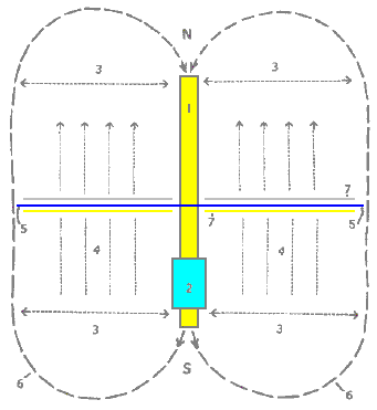
Fig.1 is a View of the Method, where N is the North and S is the South component of the Dipole.
Here, 1 marks the Dipole with its North and South components. 2 is a resonant high-voltage induction coil. 3 indicates the position of the electromagnetic wave emission from the Dipole. 4 indicates the position and flow direction of the corresponding Heaviside current component of the energy flow caused by the induction coil 2. 5 is the dielectric separator for the capacitor plates 7. 6 for the purposes of this drawing, indicates a virtual limit for the scope of the electromagnetic wave energy.
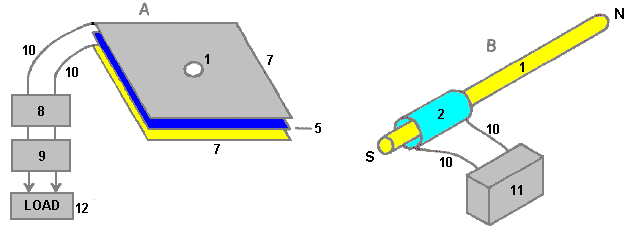
Fig.2 has two parts A and B.
In Fig.2A 1 is the hole in the capacitor plates through which the Dipole is
inserted and in Fig.2B it is the
Dipole with its North and South poles shown.
2 is the resonant
high-voltage induction coil surrounding part of the Dipole 1. The dielectric separator 5, is a thin sheet of plastic placed
between the two capacitor plates 7,
the upper plate being made of aluminium and the lower plate made of
copper. Unit 8 is a deep-cycle battery system powering a DC inverter 9 which produces 120 volts at 60 Hz
(the
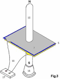
Fig.3 is a Proof Of Principal Device
using a Plasma Tube as an active Dipole.
In this drawing, 5 is the plastic
sheet dielectric separator of the two plates 7 of the capacitor, the upper plate being aluminium and the lower
plate copper. The connecting wires are
marked 10 and the plasma tube is
designated 15. The plasma tube is four feet long (1.22 m)
and six inches (150 mm) in diameter. The
high-voltage energy source for the active plasma dipole is marked 16 and there is a connector
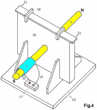
Fig.4 shows a Manufacturer's Prototype, constructed and fully tested. 1 is a metal Dipole rod and 2 the resonant high-voltage induction coil, connected through wires 10 to connector block 17 which facilitates the connection of it's high-voltage power supply. Clamps 18 hold the upper edge of the capacitor packet in place and 19 is the base plate with it's supporting brackets which hold the whole device in place. 20 is a housing which contains the capacitor plates and 21 is the point at which the power output from the capacitor plates is drawn off and fed to the DC inverter.
BEST METHOD OF CARRYING OUT THE INVENTION
The invention is applicable to any and all electrical energy requirements. The small size and it's high efficiency make it an attractive option, especially for remote areas, homes, office buildings, factories, shopping centres, public places, transportation, water systems, electric trains, boats, ships and 'all things great and small'. The construction materials are commonly available and only moderate skill levels are needed to make the device.
CLAIMS
1. Radiated magnetic flux from the Dipole, when intercepted by capacitor plates at right angles, changes into useful electrical energy.
2. A Device and Method for converting for use, normally wasted electromagnetic energy.
3. The Dipole of the Invention is any resonating substance such as Metal Rods, Coils and Plasma Tubes which have interacting Positive and Negative components.
4. The resulting Heaviside current component is changed to useful electrical energy.
****************
This patent does not make it clear that the device needs to be tuned and that the tuning is related to its physical location. The tuning will be accomplished by applying a variable-frequency input signal to the neon transformer and adjusting that input frequency to give the maximum output.
Don Smith has produced some forty eight different devices, and because he understands that the real power in the universe is magnetic and not electric, these devices have performances which appear staggering to people trained to think that electrical power is the only source of power.
The device shown below is physically quite small and yet it has an output of 160 kilowatts (8000 volts at 20 amps) from an input of 12 volts 1 amp (COP = 13,333):
This is a device which can be placed on top of a table and is not a complicated form of construction, having a very open and simplistic layout. However, some components are not mounted on this board. The twelve volt battery and connecting leads are not shown, nor are the ground connections, the step-down isolation transformer and the varistor used to protect the load from over-voltage by absorbing any random induced voltage spikes which might occur.
The device shown above has various subtle points glossed over in spite of this being one device which Don says that we should be able to reproduce ourselves. Let me state here that reproducing this seemingly simple design of Don's is not an easy thing to do and it is not something which can be thrown together by a beginner using whatever components happen to be at hand at the time. Having said that, with careful study and commonsense application of some obvious facts, it should be possible to make one of these devices, but more of these things later on when a much more detailed description of this device is given.
Another of Don's devices, somewhat similar to the one described in his patent, is shown here:
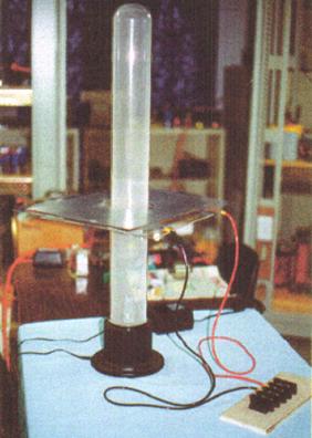
This is a larger device which uses a plasma tube four feet (1.22 m) long and 6 inches (150 mm) in diameter. The output is a massive 100 kilowatts. This is the design shown as one of the options in Don's patent. Being an Electrical Engineer, none of Don's prototypes are in the "toy" category. If nothing else is taken from Don's work, we should realise that high power outputs can be had from very simple devices.
There is one other brief document "Resonate Electrical Power System" from Don Smith which says:
Potential Energy is everywhere at all times, becoming useful when converted into a more practical form. There is no energy shortage, only grey matter. This energy potential is observed indirectly through the manifestation of electromagnetic phenomenon, when intercepted and converted, becomes useful. In nonlinear systems, interaction of magnetic waves amplify (conjugate) energy, providing greater output than input. In simple form, in the piano where three strings are struck by the hammer, the centre one is impacted and resonance activates the side strings. Resonance between the three strings provides a sound level greater than the input energy. Sound is part of the electromagnetic spectrum and is subject to all that is applicable to it.
"Useful Energy" is defined as "that which is other than Ambient". "Electric Potential" relates to mass and it's acceleration. Therefore, the Earth's Mass and Speed through space, gives it an enormous electrical potential. Humans are like the bird sitting unaware on a high voltage line. in nature, turbulence upsets ambient and we see electrical displays. Tampering with ambient, allows humans to convert magnetic waves into useful electricity.
Putting this in focus, requires a look at the Earth in general. During each of the 1,440 minutes of each day, more than 4,000 displays of lightning occur. Each display yields more than 10,000,000 volts at more than 200,000 amperes in equivalent electromagnetic flux. This is more than 57,600,000,000,000 volts and 1,152,000,000,000 amperes of electromagnetic flux during each 24 hour period. This has been going on for more than 4 billion years. The USPTO insist that the Earth's electrical field is insignificant and useless, and that converting this energy violates the laws of nature. At the same time, they issue patents in which, electromagnetic flux coming in from the Sun is converted by solar cells into DC energy. Aeromagnetic flux (in gammas) Maps World-Wide, includes those provided by the US Department of Interior-Geological Survey, and these show clearly that there is present, a spread of 1,900 gamma above Ambient, from reading instruments flown 1,000 feet above the (surface) source. Coulomb's Law requires the squaring of the distance of the remote reading, multiplied by the recorded reading. Therefore, that reading of 1,900 gamma has a corrected value of 1,900 x 1,000 x 1,000 = 1,900,000,000 gamma.
There is a tendency to confuse "gamma ray" with "gamma". "Gamma" is ordinary, everyday magnetic flux, while "gamma ray" is high-impact energy and not flux. One gamma of magnetic flux is equal to that of 100 volts RMS. To see this, take a Plasma Globe emitting 40,000 volts. When properly used, a gamma meter placed nearby, will read 400 gammas. The 1,900,000,000 gamma just mentioned, is the magnetic ambient equivalent of 190,000,000 volts of electricity. This is on a "Solar Quiet" day. On "Solar Active" days it may exceed five times that amount. The Establishment's idea that the Earth's electrical field is insignificant, goes the way of their other great ideas.
There are two kinds of electricity: "potential" and "useful". All electricity is "potential" until it is converted. The resonant-fluxing of electrons, activates the electrical potential which is present everywhere. The Intensity/CPS of the resonant-frequency-flux rate, sets the available energy. This must then be converted into the required physical dimensions of the equipment being used. For example, energy arriving from the Sun is magnetic flux, which solar cells convert to DC electricity, which is then converted further to suit the equipment being powered by it. Only the magnetic flux moves from point "A" (the Sun) to point "B" (the Earth). All electrical power systems work in exactly the same way. Movement of Coils and Magnets at point "A" (the generator) fluxes electrons, which in turn, excite electrons at point "B" (your house). None of the electrons at point "A" are ever transmitted to point "B". In both cases, the electrons remain forever intact and available for further fluxing. This is not allowed by Newtonian Physics (electrodynamics and the laws of conservation). Clearly, these laws are all screwed up and inadequate.
In modern physics, USPTO style, all of the above cannot exist because it opens a door to overunity. The good news is that the PTO has already issued hundreds of Patents related to Light Amplification, all of which are overunity. The Dynode used to adjust the self-powered shutter in your camera, receives magnetic flux from light which dislodges electrons from the cathode, reflecting electrons through the dynode bridge to the anode, resulting in billions of more electrons out than in. There are currently, 297 direct patents issued for this system, and thousands of peripheral patents, all of which support overunity. More than a thousand other Patents which have been issued, can be seen by the discerning eye to be overunity devices. What does this indicate about Intellectual Honesty?
Any coil system, when fluxed, causes electrons to spin and produce useful energy, once it is converted to the style required by its use. Now that we have described the method which is required, let us now see how this concerns us.
The entire System already exists and all that we need to do is to hook it up in a way which is useful to our required manner of use. Let us examine this backwards and start with a conventional output transformer. Consider one which has the required voltage and current handling characteristics and which acts as an isolation transformer. Only the magnetic flux passes from the input winding to the output winding. No electrons pass through from the input side to the output side. Therefore, we only need to flux the output side of the transformer to have an electrical output. Bad design by the establishment, allowing hysteresis of the metal plates, limits the load which can be driven. Up to this point, only potential is a consideration. Heat (which is energy loss) limits the output amperage. Correctly designed composite cores run cool, not hot.
A power correction factor system, being a capacitor bank, maintains an even flow of flux. These same capacitors, when used with a coil system (a transformer) become a frequency-timing system. Therefore, the inductance of the input side of the transformer, when combined with the capacitor bank, provides the required fluxing to produce the required electrical energy (cycles per second).
With the downstream system in place, all that is needed now is a potential system. Any flux system will be suitable. Any amplification over-unity output type is desirable. The input system is point "A" and the output system is point "B". Any input system where a lesser amount of electrons disturbs a greater amount of electrons - producing an output which is greater than the input - is desirable.
At this point, it is necessary to present updated information about electrons and the laws of physics. A large part of this, originates from me (Don Smith) and so is likely to upset people who are rigidly set in the thought patterns of conventional science.
Non -
Ionic Electrons
As a source of electrical energy, non-ionic electrons doublets exist in immense quantities throughout the universe. Their origin is from the emanation of Solar Plasma. When ambient electrons are disturbed by being spun or pushed apart, they yield both magnetic and electrical energy. The rate of disturbance (cycling) determines the energy level achieved. Practical methods of disturbing them include, moving coils past magnets or vice versa. A better way is the pulsing (resonant induction) with magnetic fields and waves near coils.
In coil
systems, magnetic and amperage are one package.
This suggests that electrons in their natural non-ionic state, exist as
doublets. When pushed apart by
agitation, one spins right (yielding Volts-potential electricity) and the other
spins left (yielding Amperage-magnetic energy), one being more negative than
the other. This further suggests that
when they reunite, we have (Volts x Amps =
Electron
Related Energy
Left hand spin of electrons results in Electrical Energy and right hand spin results in Magnetic Energy. Impacted electrons emit visible Light and heat.
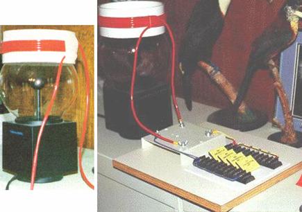
Useful
Circuits, Suggestions for Building an Operational Unit
1. Substitute a Plasma Globe such as Radio Shack's "Illumna-Storm" for the source-resonant induction system. It will have about 400 milligauss of magnetic induction. One milligauss is equal to 100 volts worth of magnetic induction.
2. Construct a coil using a 5-inch to 7-inch (125 to 180 mm) diameter piece of PVC for the coil former.
3. Get about 30 feet (10 m) of Jumbo-Speaker Cable and separate the two strands. This can be done by sticking a carpet knife into a piece of cardboard or wood, and then pulling the cable carefully past the blade to separate the two insulated cores from each other. (PJK Note: "Jumbo-Speaker Cable" is a vague term as that cable comes in many varieties, with anything from a few, to over 500 strands in each core).
4. Wind the coil with 10 to 15 turns of wire and leave about 3 feet (1 m) of cable spare at each end of the coil. Use a glue gun to hold the start and finish of the coil.
5. This will become the "L - 2" coil shown in the Circuits page.
6. When sitting on top of the Plasma Globe (like a crown) you have a first-class resonant air-core coil system.
7. Now, substitute two or more capacitors (rated at 5,000 volts or more) for the capacitor bank shown on the Circuits page. I use more than two 34 microfarad capacitors.
8. Finish out the circuit as shown. You are now in business !
9. Voltage - Amperage limiting resistors are required across the output side of the Load transformer. These are used to adjust the output level and the desired cycles per second.
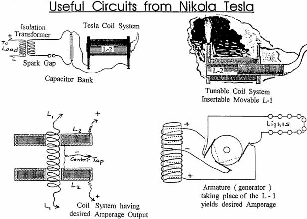
Don Smith's Suggestions: Get a copy of the "Handbook of Electronic Tables and Formulas", published by Sams, ISBN 0-672-22469-0, also an Inductance/Capacitance/Resistance meter is required. Chapter 1 of Don's pdf document has important time-constant (frequency) information and a set of reactance charts in nomograph style ("nomograph": a graph, usually containing three parallel scales graduated for different variables so that when a straight line connects values of any two, the related value may be read directly from the third at the point intersected by the line) which makes working, and approximating of the three variables (capacitance, inductance and resistance) much easier. If two of the variables are known, then the third one can be read from the nomograph.
For example, if the input side of the isolation transformer needs to operate at 60 Hz, that is 60 positive cycles and 60 negative cycles, being a total of 120 cycles. Read off the inductance in Henries by using an Inductance meter attached to the input side of the isolation transformer. Plot this value on the (nomographic) reactance chart. Plot the needed 120 Hz on the chart and connect these two points with a straight line. Where this line crosses the Farads line and the Ohms line, gives us two values. Choose one (resistor) and insert it between the two leads of the transformer input winding.
The Power Correction Factor Capacitor (or bank of more than one capacitor) now needs adjusting. The following formula is helpful in finding this missing information. The capacitance is known, as is the desired potential to pulse the output transformer. One Farad of capacitance is one volt for one second (one Coulomb). Therefore, if we want to keep the bucket full with a certain amount, how many dippers full are needed? If the bucket needs 120 volts, then how many coulombs are required?
![]()
Now, go to the nomograph mentioned above, and find the required resistor jumper to place between the poles of the Correction Factor Capacitor.
An earth
grounding is desirable, acting as both a voltage-limiter and a transient spike
control. Two separate earths are
necessary, one at the Power Factor Capacitor and one at the input side of the
isolation transformer. Off-the-shelf
surge arrestors / spark gaps and varistors having the desired voltage/potential
and amperage control are commonly available.
Siemens, Citel
It should be obvious that several separate closed circuits are present in the suggested configuration: The power input source, the high-voltage module, a power factor capacitor bank combined with the input side of the isolation transformer. Lastly, the output side of the isolation transformer and its load. None of the electrons active at the power source (battery) are passed through the system for use downstream. At any point, if the magnetic flux rate should happen to vary, then the number of active electrons also varies. Therefore, controlling the flux rate controls the electron (potential) activity. Electrons active at point "A" are not the same electrons which are active at point "B", or those at point "C", and so on. If the magnetic flux rate (frequency Hz) varies, then a different number of electrons will be disturbed. This does not violate any Natural Law and it does produce more output energy than the input energy, should that be desirable.
A convenient high-voltage module is a 12 volt DC neon tube transformer. The Power Factor Correction Capacitors should be as many microfarads as possible as this allows a lower operating frequency. The 12-volt neon tube transformer oscillates at about 30,000 Hz. At the Power Correction Factor Capacitor bank we lower the frequency to match the input side of the isolation transformer.
Other convenient high-voltage sources are car ignition coils, television flyback transformers, laser printer modules, and various other devices. Always lower the frequency at the Power Factor Correction Capacitor and correct, if needed, at the input side of the isolation transformer. The isolation transformer comes alive when pulsed. Amperage becomes a part of the consideration only at the isolation transformer. Faulty design, resulting in hysteresis, creates heat which self-destructs the transformer if it is overloaded. Transformers which have a composite core instead of the more common cores made from many layers of thin sheets of soft iron, run cool and can tolerate much higher amperage.

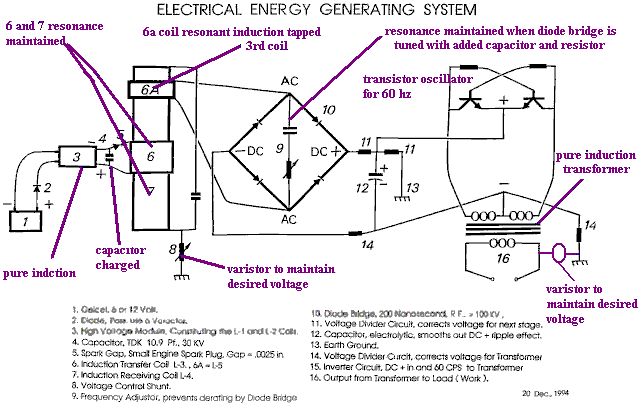
The information shown above, relates to the small Suitcase Model demonstrated at the 1996 Tesla Convention, presented as Don Smiths' Workshop. This unit was a very primitive version and newer versions have atomic batteries and power output ranges of Gigawatts. The battery requirement is low level and is no more harmful than the radium on the dial of a clock. Commercial units of Boulder Dam size are currently being installed at several major locations throughout the world. For reasons of Don's personal security and contract obligations, the information which he has shared here, is incomplete.

***************************
PJK: I am most definitely not an expert in this area. However, it is probably worth mentioning some of the main points which Don Smith appears to be making. There are some very important points being made here, and grasping these may make a considerable difference to our ability to tap into the excess energy available in our local environment. There are four points worth mentioning:
1. Voltage
2. Frequency
3. Magnetic / Electric relationship
4. Resonance
1. Voltage. We tend to view things with an 'intuitive' view, generally based on fairly simple concepts. For example, we automatically think that it is more difficult to pick up a heavy object than to pick up a light one. How much more difficult? Well, if it is twice as heavy, it would probably be about twice as much effort to pick it up. This view has developed from our experience of things which we have done in the past, rather than on any mathematical calculation or formula.
Well, how
about pulsing an electronic system with a voltage? How would the output power of a system be
affected by increasing the voltage? Our
initial 'off-the cuff' reaction might be that the power output might be
increased a bit, but then hold on… we've just remembered that
Don Smith points out that as capacitors and coils store energy, if they are involved in the circuit, then the output power is proportional to the square of the voltage used. Double the voltage, and the output power is four times greater. Use three times the voltage and the output power is nine times greater. Use ten times the voltage and the output power is one hundred times greater !
Don says that the energy stored, multiplied by the cycles per second, is the energy being pumped by the system. Capacitors and inductors (coils) temporarily store electrons, and their performance is given by:
Capacitor formula: W = 0.5 x C x V2 x Hz where:
W is the energy in Joules (Joules = Volts x Amps x seconds)
C is the capacitance in Farads
V is the voltage
Hz is the cycles per second
Inductor formula: W = 0.5 x L x A2 x Hz where:
W is the energy in Joules
L is the inductance in henrys
A is the current in amps
Hz is the frequency in cycles per second
You will notice that where inductors (coils) are involved, then the output power goes up with the square of the current. Double the voltage and double the current gives four times the power output due to the increased voltage and that increased output is increased by a further four times due to the increased current, giving sixteen times the output power.
2. Frequency. You will notice from the formulas above, that the output power is directly proportional to the frequency "Hz". The frequency is the number of cycles per second (or pulses per second) applied to the circuit. This is something which is not intuitive for most people. If you double the rate of pulsing, then you double the power output. When this sinks in, you suddenly see why Nikola Tesla tended to use millions of volts and millions of pulses per second.
However, Don Smith states that when a circuit is at it's point of resonance, resistance in the circuit drops to zero and the circuit becomes effectively, a superconductor. The energy for such a system which is in resonance is:
Resonant circuit: W = 0.5 x C x V2 x (Hz)2 where:
W is the energy in Joules
C is the capacitance in Farads
V is the voltage
Hz is the cycles per second
If this is
correct, then raising the frequency in a resonating circuit has a massive
effect on the power output of the device.
The question then arises: why is the mains power in Europe just fifty
cycles per second and in
However, if we want to extract energy from the environment, then we should go for high voltage and high frequency. Then, when high power has been extracted, if we want a low frequency suited to electric motors, we can pulse the already captured power at that low frequency.
It might be speculated that if a device is being driven with sharp pulses which have a very sharply rising leading edge, that the effective frequency of the pulsing is actually determined by the speed of that rising edge, rather than the rate at which the pulses are actually generated. For example, if pulses are being generated at, say, 50 kHz but the pulses have a leading edge which would be suited to a 200 kHz pulse train, then the device might well see the signal as a 200 kHz signal with a 25% Mark/Space ratio, the very suddenness of the applied voltage having a magnetic shocking effect equivalent to a 200 kHz pulse train.
3. Magnetic / Electric relationship. Don states that the reason why our present power systems are so inefficient is because we concentrate on the electric component of electromagnetism. These systems are always COP<1 as electricity is the 'losses' of electromagnetic power. Instead, if you concentrate on the magnetic component, then there is no limit on the electric power which can be extracted from that magnetic component. Contrary to what you might expect, if you install a pick-up system which extracts electrical energy from the magnetic component, you can install any number of other identical pick-ups, each of which extract the same amount of electrical energy from the magnetic input, without loading the magnetic wave in any way. Unlimited electrical output for the 'cost' of creating a single magnetic effect.
The magnetic effect which we want to create is a ripple in the zero-point energy field, and ideally, we want to create that effect while using very little power. Creating a dipole with a battery which has a Plus and a Minus terminal or a magnet which has North and South poles, is an easy way to do create an electromagnetic imbalance in the local environment. Pulsing a coil is probably an even better way as the magnetic field reverses rapidly if it is an air-core coil, such as a Tesla Coil. Using a ferromagnetic core to the coil can create a problem as iron can't reverse it's magnetic alignment very rapidly, and ideally, you want pulsing which is at least a thousand times faster than iron can handle.
 Don
draws attention to the "Transmitter / Receiver" educational kit
"Resonant Circuits #10-416"
which was supplied by The Science Source,
Don
draws attention to the "Transmitter / Receiver" educational kit
"Resonant Circuits #10-416"
which was supplied by The Science Source,
If you get the Science Source educational kit, then there are some details which you need to watch out for. The unit has two very nice quality plastic bases and two very neatly wound coils each of 60 turns of 0.47 mm diameter enamelled copper wire on clear acrylic tubes 57 mm (2.25”) in diameter. The winding covers a 28 mm section of the tube. The layout of the transmitter and receiver modules does not match the accompanying instruction sheet and so considerable care needs to be taken when wiring up any of their circuits. The circuit diagrams are not shown, just a wiring diagram, which is not great from an educational point of view. The one relevant circuit is:

Before you buy the kit, it is not mentioned that in order to use it, you now need a signal generator capable of producing a 10-volt signal at 1 MHz. The coil has a DC resistance of just 1.9 ohms but at a 1 MHz resonant frequency, the necessary drive power is quite low.
A variable capacitor is mounted on the receiver coil tube, but the one in my kit made absolutely no difference to the frequency tuning, nor was my capacitance meter able to determine any capacitance value for it at all, even though it had no trouble at all in measuring the 101 pF capacitor which was exactly the capacitance printed on it. For that reason, it is shown in blue in the circuit diagram above. Disconnecting it made no difference whatsoever.
In this particular kit, standard screw connectors have had one screw replaced with an Allen key headed bolt which has a head large enough to allow finger tightening. Unfortunately, those bolts have a square cut tip where a domed tip is essential if small diameter wires are to be clamped securely. If you get the kit, then I suggest that you replace the connectors with a standard electrical screw connector strip.
In tests, the LED lights up when the coils are aligned and within about 100 mm of each other, or if they are close together side by side. This immediately makes the Hubbard device spring to mind. Hubbard has a central "electromagnetic transmitter" surrounded by a ring of "receivers" closely coupled magnetically to the transmitter, each of which will receive a copy of the energy sent by the transmitter:

Don points to an even more clearly demonstrated occurrence of this effect in the Tesla Coil. In a typical Tesla Coil, the primary coil is much larger diameter than the inner secondary coil:
![]()
If, for example, 8,000 volts is applied to the primary coil which has four turns, then each turn would have 2,000 volts of potential. Each turn of the primary coil transfers electromagnetic flux to every single turn of the secondary winding, and the secondary coil has a very large number of turns. Massively more power is produced in the secondary coil than was used to energise the primary coil. A common mistake is to believe that a Tesla Coil can't produce serious amperage. If the primary coil is positioned in the middle of the secondary coil as shown, then the amperage generated will be as large as the voltage generated. A low power input to the primary coil can produce kilowatts of usable electrical power as described in chapter 5.
4. Resonance. An important factor in circuits aimed at tapping external energy is resonance. It can be hard to see where this comes in when it is an electronic circuit which is being considered. However, everything has it's own resonant frequency, whether it is a coil or any other electronic component. When components are connected together to form a circuit, the circuit has an overall resonant frequency. As a simple example, consider a swing:

If the swing is pushed before it reaches the highest point on the mother's side, then the push actually opposes the swinging action. The time of one full swing is the resonant frequency of the swing, and that is determined by the length of the supporting ropes holding the seat and not the weight of the child nor the power with which the child is pushed. Provided that the timing is exactly right, a very small push can get a swing moving in a substantial arc. The key factor is, matching the pulses applied to the swing, that is, to the resonant frequency of the swing. Get it right and a large movement is produced. Get it wrong, and the swing doesn't get going at all (at which point, critics would say "see, see …swings just don't work - this proves it !!"). This principle is demonstrated in the video at http://www.youtube.com/watch?v=irwK1VfoiOA.
Establishing the exact pulsing rate needed for a resonant circuit is not particularly easy, because the circuit contains coils (which have inductance, capacitance and resistance), capacitors (which have capacitance and a small amount of resistance) and resistors and wires, both of which have resistance and some capacitance. These kinds of circuit are called "LRC" circuits because "L" is the symbol used for inductance, "R" is the symbol used for resistance and "C" is the symbol used for capacitance.
Don Smith provides instructions for winding and using the type of air-core coils needed for a Tesla Coil. He says:
1. Decide a frequency and bear in mind, the economy of the size of construction selected. The factors are:
(a) Use radio frequency (above 20 kHz).
(b) Use natural frequency, i.e. match the coil wire length to the frequency - coils have both capacitance and inductance.
(c) Make the wire length either one quarter, one half of the full wavelength.
(d) Calculate the wire length in feet as follows:
If using one quarter wavelength, then divide 247 by the frequency in MHz.
If using one half wavelength, then divide 494 by the frequency in MHz.
If using the full wavelength, then divide 998 by the frequency in MHz.
For wire lengths in metres:
If using one quarter wavelength, then divide 75.29 by the frequency in MHz.
If using one half wavelength, then divide 150.57 by the frequency in MHz.
If using the full wavelength, then divide 304.19 by the frequency in MHz.
2. Choose the number of turns to be used in the coil when winding it using the wire length just calculated. The number of turns will be governed by the diameter of the tube on which the coil is to be wound. Remember that the ratio of the number of turns in the "L - 1" and "L - 2" coils, controls the overall output voltage. For example, if the voltage applied the large outer coil "L - 1" is 2,400 volts and L - 1 has ten turns, then each turn of L - 1 will have 240 volts dropped across it. This 240 volts of magnetic induction transfers 240 volts of electricity to every turn of wire in the inner "L - 2" coil. If the diameter of L - 2 is small enough to have 100 turns, then the voltage produced will be 24,000 volts. If the diameter of the L - 2 former allows 500 turns, then the output voltage will be 120,000 volts.
3. Choose the length and diameter of the coils. The larger the diameter of the coil, the fewer turns can be made with the wire length and so the coil length will be less, and the output voltage will be lower.
4. For example, if 24.7 MHz is the desired output frequency, then the length of wire, in feet, would be 247 divided by 24.7 which is 10 feet of wire (3,048 mm). The coil may be wound on a standard size of PVC pipe or alternatively, it can be purchased from a supplier - typically, an amateur radio supply store.
If the voltage on each turn of L - 1 is arranged to be 24 volts and the desired output voltage 640 volts, then there needs to be 640 / 24 = 26.66 turns on L - 2, wound with the 10 feet of wire already calculated.
Note: At this point, Don's calculations go
adrift and he suggests winding 30 turns on a 2-inch former. If you do that, then it will take about 16
feet of wire and the resonant point at 10-feet will be at about 19 turns,
giving an output voltage of 458 volts instead of the required 640 volts, unless
the number of turns on L - 1 is reduced to give more than 24 volts per
turn. However, the actual required
diameter of the coil former (plus one diameter of the wire) is 10 x 12 / (26.67
x 3.14159) = 1.43 inches. You can make
this size of former up quite easily if you want to stay with ten turns on the L
- 1 coil.
5. Connect to the start of the coil. To determine the exact resonant point on the coil, a measurement is made. Off-the-shelf multimeters are not responsive to high-frequency signals so a cheap neon is used instead. Holding one wire of the neon in one hand and running the other neon wire along the outside of the L - 2 winding, the point of brightest light is located. Then the neon is moved along that turn to find the brightest point along that turn, and when it is located, a connection is made to the winding at that exact point. L - 2 is now a resonant winding. It is possible to increase the ("Q") effectiveness of the coil by spreading the turns out a bit instead of positioning them so that each turn touches both of the adjacent turns.
6. The input power has been suggested as 2,400 volts. This can be constructed from a Jacob's ladder arrangement or any step-up voltage system. An off-the-shelf module as used with lasers is another option.
7. Construction of the L - 1 input coil has been suggested as having 10 turns. The length of the wire in this coil is not critical. If a 2-inch diameter PVC pipe was used for the L - 2 coil, then the next larger size of PVC pipe can be used for the L - 1 coil former. Cut a 10-turn length of the pipe (probably a 3-inch diameter pipe). The pipe length will depend on the diameter of the insulated wire used to make the winding. Use a good quality multimeter or a specialised LCR meter to measure the capacitance (in Farads) and the inductance (in henrys) of the L - 2 coil. Now, put a capacitor for matching L - 1 to L - 2 across the voltage input of L - 1, and a spark gap connected in parallel is required for the return voltage from L - 1. A trimmer capacitor for L - 1 is desirable.
8. The performance of L - 2 can be further enhanced by attaching an earth connection to the base of the coil. The maximum output voltage will be between the ends of coil L - 2 and lesser voltages can be taken off intermediate points along the coil if that is desirable.
This frequency information can be rather hard to understand in the way that Don states it. It may be easier to follow the description given by one developer who says:
I have noticed that any machine can be made a
super machine just by adding a bipolar capacitor across the coil. Nothing else is needed. With the correct capacitor the coil becomes
Naturally Resonant and uses very little Amperage. Each machine uses a different size
capacitor. The correct capacitor size
can be calculated by dividing the speed of light by the coil's wire length
first to get the coil's Natural Frequency and then dividing the voltage to be
used by that frequency. The result is
the correct size for the capacitor. Your machine will then be very powerful
even working from a 12V car battery, no other additions needed.
My coil's wire length is 497.333 meters.
299000000 m/sec / 497.333 m = 600000 Hz.
12V / 600000 = 0.00002 or 20 microfarads. A beautiful Naturally Resonant Tank
circuit. You can use this with any coil
for overunity!
Once we have a Naturally Resonant
Coil/Capacitor combination we can bring the frequency down to 50 Hz by
calculating for the Power Factor Correction:
Hz = Resistance x Farads then
50 Hz = R x 0.00002
so
50 / 0.00002 = 2500000
and R
= 2500000 or 2.5 Meg Ohms.
We then place all
three components in parallel and our coil should give us a 50 Hz output.
Don provides quite an amount of information on one of his devices shown here:

Without his description of the device, it would be difficult to understand it's construction and method of operation. As I understand it, the circuit of what is mounted on this board is as shown here:
This arrangement has bothered some readers recently as they feel that the spark gap should be in series with the L1 coil, like this:
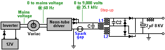
This is understandable, as there is always a tendency to think of the spark gap as being a device which is there to protect against excessive voltages rather than seeing it as an active component of the circuit, a component which is in continuous use. In 1925, Hermann Plauson was granted a patent for a whole series of methods for converting the high voltage produced by a tall aerial system into useable, standard electricity. Hermann starts off by explaining how high voltage can be converted into a convenient form and he uses a Wimshurst static electricity generator as an example of a constant source of high voltage. The output from a rectified Tesla Coil, a Wimshurst machine and a tall aerial are very much alike, and so Hermann's comments are very relevant here. He shows it like this:
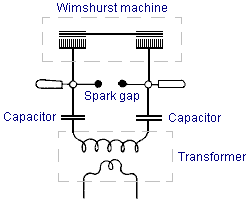
Here, the
output of the Wimshurst machine is stored in two high-voltage capacitors (
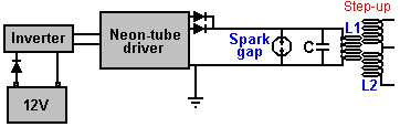
Here the high voltage comes from the battery/inverter/neon-tube driver/rectifiers, rather than from a mechanically driven Wimshurst machine. He has the same build up of voltage in a capacitor with a spark gap across the capacitor. The spark gap will fire when the capacitor voltage reaches its designed level. The only difference is in the positioning of the capacitor, which if it matched Hermann's arrangement exactly, would be like this:
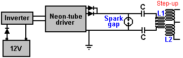
which would be a perfectly viable arrangement as far as I can see. You will remember that Tesla, who always speaks very highly of the energy released by the very sharp discharge produced by a spark, shows a high-voltage source feeding a capacitor with the energy passing through a spark gap to the primary winding of a transformer:
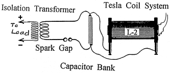
However, with Don's arrangement, it can be a little difficult to see why the capacitor is not short-circuited by the very low resistance of the few turns of thick wire forming the L1 coil. Well, it would do that if we were operating with DC, but we are most definitely not doing that as the output from the neon-tube driver circuit is pulsing 35,000 times per second. This causes the DC resistance of the L1 coil to be of almost no consequence and instead, the coil's "impedance" or "reactance" (effectively, it's AC resistance) is what counts. Actually, the capacitor and the L1 coil being connected across each other have a combined "reactance" or resistance to pulsing current at this frequency. This is where the nomograph diagram comes into play, and there is a much easier to understand version of it a few pages later on in this document. So, because of the high pulsing frequency, the L1 coil does not short-circuit the capacitor and if the pulsing frequency matches the resonant frequency of the L1 coil (or a harmonic of that frequency), then the L1 coil will actually have a very high resistance to current flow through it. This is how a crystal set radio receiver tunes in a particular radio station, broadcasting on it's own frequency.
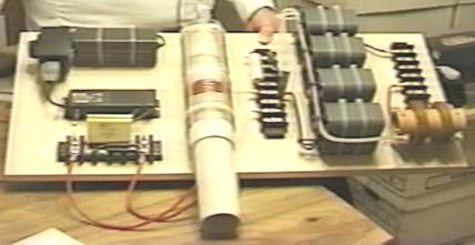
Anyway, coming back to Don's device shown in the photograph above, the electrical drive is from a 12-volt battery which is not seen in the photograph. Interestingly, Don remarks that if the length of the wires connecting the battery to the inverter are exactly one quarter of the wave length of the frequency of the oscillating magnetic field generated by the circuit, then the current induced in the battery wires will recharge the battery continuously, even if the battery is supplying power to the circuit at the same time.
The battery supplies a small current through a protecting diode, to a standard off-the-shelf "true sine-wave" inverter. An inverter is a device which produces mains-voltage Alternating Current from a DC battery. As Don wants adjustable voltage, he feeds the output from the inverter into a variable transformer called a "Variac" although this is often made as part of the neon-driver circuit to allow the brightness of the neon tube to be adjusted by the user. This arrangement produces an AC output voltage which is adjustable from zero volts up to the full mains voltage (or a little higher, though Don does not want to use a higher voltage). The use of this kind of adjustment usually makes it essential for the inverter to be a true sine-wave type. As the power requirement of the neon-tube driver circuit is so low, the inverter should not cost very much.
The neon-tube driver circuit is a standard off-the-shelf device used to drive neon tube displays for commercial establishments. The one used by Don contains an oscillator and a step-up transformer, which together produce an Alternating Current of 9,000 volts at a frequency of 35,100 Hz (sometimes written as 35.1 kHz). The term "Hz" stands for "cycles per second". Don lowers the 9,000 volts as he gets great power output at lower input voltages and the cost of the output capacitors is a significant factor. The particular neon-tube driver circuit which Don is using here, has two separate outputs out of phase with each other, so Don connects them together and uses a blocking diode in each line to prevent either of them affecting the other one. Not easily seen in the photograph, the high-voltage output line has a very small, encapsulated, Gas-Discharge Tube spark gap in it and the line is also earthed. The device looks like this:
![]()
Please note that when an earth connection is mentioned in connection with Don Smith's devices, we are talking about an actual wire connection to a metal object physically buried in the ground, whether it is a long copper rod driven into the ground, or an old car radiator buried in a hole like Tariel Kapanadze uses. When Thomas Henry Moray performed his requested demonstration deep in the countryside at a location chosen by the sceptics, the light bulbs which formed his demonstration electrical load, glowed more brightly with each hammer stroke as a length of gas pipe was hammered into the ground to form his earth connection.
It should be
remarked that since Don purchased his neon-tube driver module that newer
designs have generally taken over completely, especially in
The output of the neon-tube driver circuit is used to drive the primary "L1" winding of a Tesla Coil style transformer. This looks ever so simple and straightforward, but there are some subtle details which need to be considered.
The operating frequency of 35.1 kHz is set and maintained by the neon-tube driver circuitry, and so, in theory, we do not have to do any direct tuning ourselves. However, we want the resonant frequency of the L1 coil and the capacitor across it to match the neon-driver circuit frequency. The frequency of the "L1" coil winding will induce exactly the same frequency in the "L2" secondary winding. However, we need to pay special attention to the ratio of the wire lengths of the two coil windings as we want these two windings to resonate together. A rule of thumb followed by most Tesla Coil builders is to have the same weight of copper in the L1 and L2 coils, which means that the wire of the L1 coil is usually much thicker than the wire of the L2 coil. If the L1 coil is to be one quarter of the length of the L2 coil, then we would expect the cross-sectional area of the L1 coil to be four times that of the wire of the L2 coil and so the wire should have twice the diameter (as the area is proportional to the square of the radius, and the square of two is four).
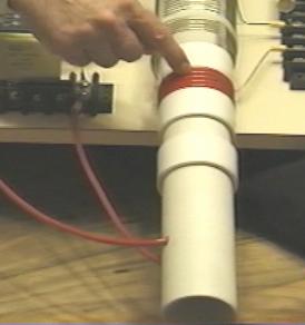
Don uses a white plastic tube as the former for his "L1" primary coil winding. As you can see here, the wire is fed into the former, leaving sufficient clearance to allow the former to slide all the way into the outer coil. The wire is fed up inside the pipe and out through another hole to allow the coil turns to be made on the outside of the pipe. There appear to be five turns, but Don does not always go for a complete number of turns, so it might be 4.3 turns or some other value. The key point here is that the length of wire in the "L1" coil turns should be exactly one quarter of the length of wire in the "L2" coil turns.
The "L2" coil used here is a commercial 3-inch diameter unit from Barker & Williamson, constructed from uninsulated, solid, single-strand "tinned" copper wire (how to make home-build versions is shown later on). Don has taken this coil and unwound four turns in the middle of the coil in order to make a centre-tap. He then measured the exact length of wire in the remaining section and made the length of the "L1" coil turns to be exactly one quarter of that length. The wire used for the "L1" coil looks like Don's favourite "Jumbo Speaker Wire" which is a very flexible wire with a very large number of extremely fine uninsulated copper wires inside it.
You will notice that Don has placed a plastic collar on each side of the winding, matching the thickness of the wire, in order to create a secure sliding operation inside the outer "L2" coil, and the additional plastic collars positioned further along the pipe provide further support for the inner coil. This sliding action allows the primary coil "L1" to be positioned at any point along the length of the "L2" secondary coil, and that has a marked tuning effect on the operation of the system. The outer "L2" coil does not have any kind of tube support but instead, the coil shape is maintained by the stiffness of the solid wire plus four slotted strips. This style of construction produces the highest possible coil performance at radio frequencies. With a Tesla Coil, it is most unusual to have the L1 coil of smaller diameter than the L2 coil.
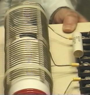
The "L2" coil has two separate sections, each of seventeen turns. One point to note is the turns are spaced apart using slotted strips to support the wires and maintain an accurate spacing between adjacent turns. It must be remembered that spacing coil turns apart like this alters the characteristics of the coil, increasing it's "capacitance" factor substantially. Every coil has resistance, inductance and capacitance, but the form of the coil construction has a major effect on the ratio of these three characteristics. The coil assembly is held in position on the base board by two off-white plastic cable ties. The nearer half of the coil is effectively connected across the further half as shown in the circuit diagram above.
One point which Don stresses, is that the length of the wire in the "L1" coil and the length of wire in the "L2" coil, must be an exact even division or multiple of each other (in this case, the "L2" wire length in each half of the "L2" coil is exactly four times as long as the "L1" coil wire length). This is likely to cause the "L1" coil to have part of a turn, due to the different coil diameters. For example, if the length of the "L2" coil wire is 160 inches and "L1" is to be one quarter of that length, namely, 40 inches. Then, if the "L1" coil has an effective diameter of 2.25 inches, (allowing for the thickness of the wire when wound on a 2-inch diameter former), then the "L1" coil would have 5.65 (or 5 and 2/3) turns which causes the finishing turn of "L2" to be 240 degrees further around the coil former than the start of the first turn - that is, five full turns plus two thirds of the sixth turn.
The L1 / L2 coil arrangement is a Tesla Coil. The positioning of the "L1" coil along the length of the "L2" coil, adjusts the voltage to current ratio produced by the coil. When the "L1" coil is near the middle of the "L2" coil, then the amplified voltage and amplified current are roughly the same. The exact wire ratio of these two coils gives them an almost automatic tuning with each other, and the exact resonance between them can be achieved by the positioning of the "L1" coil along the length of the "L2" coil. While this is a perfectly good way of adjusting the circuit, in the build shown in the photograph, Don has opted to get the exact tuning by connecting a capacitor across "L1" as marked as "C" in the circuit diagram. Don found that the appropriate capacitor value was around the 0.1 microfarad (100 nF) mark. It must be remembered that the voltage across "L1" is very high, so if a capacitor is used in that position it will need a voltage rating of at least 9,000 volts. Don remarks that the actual capacitors seen in the photograph of this prototype are rated at fifteen thousand volts, and were custom made for him using a "self-healing" style of construction. As has already been remarked, this capacitor is an optional component. Don also opted to connect a small capacitor across the "L2" coil, also for fine-tuning of the circuit, and that component is optional and so is not shown on the circuit diagram. As the two halves of the "L2" coil are effectively connected across each other, it is only necessary to have one fine-tuning capacitor. However, Don stresses that the "height" length of the coil (when standing vertically) controls the voltage produced while the coil "width" (the diameter of the turns) controls the current produced.
The exact wire length ratio of the turns in the "L1" and "L2" coils gives them an almost automatic synchronous tuning with each other, and the exact resonance between them can be achieved by the positioning of the "L1" coil along the length of the "L2" coil. While this is a perfectly good way of adjusting the circuit, in the 1994 build shown in the photograph, Don has opted to get the exact tuning by connecting a capacitor across "L1" as marked as "C" in the circuit diagram. Don found that the appropriate capacitor value for his particular coil build, was about 0.1 microfarad (100 nF) and so he connected two 47 nF high-voltage capacitors in parallel to get the value which he wanted. It must be remembered that the voltage across "L1" is very high, so a capacitor used in that position needs a voltage rating of at least 9,000 volts. Don remarks that the actual capacitors seen in the photograph of this prototype are rated at fifteen thousand volts, and were custom made for him using a "self-healing" style of construction.
Don has also connected a small capacitor across the "L2" coil, and that optional component is marked as "C2" in the circuit diagram and the value used by Don happened to be a single 47nF, high-voltage capacitor. As the two halves of the "L2" coil are effectively connected across each other, it is only necessary to have one capacitor for "L2":
There are various ways of dealing with the output from the "L2" coil in order to get large amounts of conventional electrical power out of the device. The method shown here uses the four very large capacitors seen in the photograph. These have an 8,000 or 9,000 volt rating and a large capacity and they are used to store the circuit power as DC prior to use in the load equipment. This is achieved by feeding the capacitor bank through a diode which is rated for both high voltage and high current, as Don states that the device produces 8,000 volts at 20 amps, in which case, this rectifying diode has to be able to handle that level of power, both at start-up when the capacitor bank is fully discharged and "L2" is producing 8,000 volts, and when the full load of 20 amps is being drawn.
This capacitor bank is fed through a diode which is rated for both high voltage and high current, as Don states that the device produces 8,000 volts at 20 amps, in which case, this rectifying diode has to be able to handle that level of power, both at start-up when the capacitor bank is fully discharged and "L2" is producing 8,000 volts, and when the full load of 20 amps is being drawn. The actual diodes used by Don happen to be rated at 25 KV but that is a far greater rating than is actually needed.
In passing, it might be remarked that the average home user will not have an electrical requirement of anything remotely like as large as this, seeing that 10 kW is more than most people use on a continuous basis, while 8 KV at 20 A is a power of 160 kilowatts. As the neon-tube driver circuit can put out 9,000 volts and since the L1 / L2 coil system is a step-up transformer, if the voltage fed to the capacitor bank is to be kept down to 8,000 volts, then the Variac adjustment must be used to reduce the voltage fed to the neon-tube driver circuit, in order to lower the voltage fed to the L1 / L2 coil pair, typically, to 3,000 volts.
A very astute and knowledgeable member of the EVGRAY Yahoo EVGRAY forum whose ID is "silverhealtheu" has recently pointed out that Don Smith says quite freely that he does not disclose all of the details of his designs, and it is his opinion that a major item which has not been disclosed is that the diodes in the circuit diagrams shown here are the wrong way round and that Don operates his voltages in reverse to the conventional way. In fact, the circuit diagram should be:
He comments: "the diodes leaving the Neon-tube Driver may need to be
reversed as we want to collect the negative polarity. The spark gap will then operate on ambient
inversion and the spark will look and sound totally different with a much
faster crack and producing very little heat and even becoming covered in frost is
possible.
The Variac should be raised up just enough to get a spark going then backed off
slightly. Any higher voltage is liable
to make the Neon-tube Driver think that it has a short-circuit condition, and
the new electronic designs will then shut down automatically and fail to
operate at all if this method is not followed.
When running, C, L1 and L2 operate somewhere up in the Radio Frequency band
because the Neon-tube Driver only acts as a tank-circuit exciter. The
large collection capacitor C3, should fill inverted to earth polarity as shown
above. The load will then be pulling
electrons from the earth as the cap is REFILLED back to ZERO rather than the
joules in the capacitor being depleted.
Also remember that the Back-EMF systems of John Bedini and others, create a
small positive pulse but they collect a super large NEGATIVE polarity spike
which shoots off the bottom of an oscilloscope display. This is what we want, plenty of this stored
in capacitors, and then let the ambient background energy supply the current
when it makes the correction."
This is a very important point and it may well make a really major difference to the performance of a device of this nature.

One reader has drawn attention to the fact that Don's main document indicates that there should be a resistor "R" across the L1 coil as well as the capacitor "C" and he suggests that the circuit should actually be as shown above, considering what Don said earlier about his "suitcase" design. Another reader points out that the wire in the output choke shown in the photograph below appears to be wound with wire that is far too small diameter to carry the currents mentioned by Don. It seems likely that a choke is not needed in that position except to suppress possible radio frequency transmissions from the circuit, but a more powerful choke can easily be wound using larger diameter wire.
When the circuit is running, the storage capacitor bank behaves like an 8,000 volt battery which never runs down and which can supply 20 amps of current for as long as you want. The circuitry for producing a 220 volt 50 Hz AC output or a 110 volt 60 Hz AC output from the storage capacitors is just standard electronics. In passing, one option for charging the battery is to use the magnetic field caused by drawing mains-frequency current pulses through the output "choke" coil, shown here:
The output current flows through the left hand winding on the brown cylindrical former, and when the photograph was taken, the right-hand winding was no longer in use. Previously, it had been used to provide charging power to the battery by rectifying the electrical power in the coil, caused by the fluctuating magnetic field caused by the pulsing current flowing through the left hand winding, as shown here:
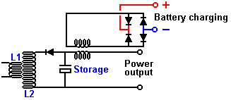
The DC output produced by the four diodes was then used to charge the driving battery, and the power level produced is substantially greater than the minor current drain from the battery. Consequently, it is a sensible precaution to pass this current to the battery via a circuit which prevents the battery voltage rising higher than it should. A simple voltage level sensor can be used to switch off the charging when the battery has reached its optimum level. Other batteries can also be charged if that is wanted. Simple circuitry of the type shown in chapter 12 can be used for controlling and limiting the charging process. The components on Don's board are laid out like this:
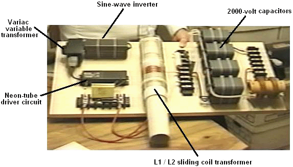
Don draws attention to the fact that the cables used to connect the output of "L2" to the output of the board, connecting the storage capacitors on the way, are very high-voltage rated cables with special multiple coverings to ensure that the cables will remain sound over an indefinite period. It should be remarked at this point, that the outer 3" diameter coil used by Don, is not wound on a former, but in order to get higher performance at high frequencies, the turns are supported with four separate strips physically attached to the turns - the technique described later in this document as being an excellent way for home construction of such coils.
Please bear in mind
that the voltages here and their associated power levels are literally lethal
and perfectly capable of killing anyone who handles the device carelessly when
it is powered up. When a replication of
this device is ready for routine use, it must be encased so that none of the
high-voltage connections can be touched by anyone. This is not a suggestion, but it is a
mandatory requirement, despite the fact that the components shown in the
photographs are laid out in what would be a most dangerous fashion were the
circuit to be powered up as it stands.
Under no circumstances, construct and test this circuit unless you are
already experienced in the use of high-voltage circuits or can be supervised by
somebody who is experienced in this field.
This is a "one hand in the pocket at all times" type of
circuit and it needs to be treated with great care and respect at all times, so
be sensible.
The remainder of the circuit is not mounted on the board, possibly because there are various ways in which the required end result can be achieved. The one suggested here is perhaps the most simple solution:
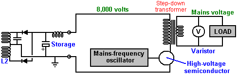
The voltage has to be dropped, so an iron-cored mains-frequency step-down transformer is used to do this. To get the frequency to the standard mains frequency for the country in which the device is to be used, an oscillator is used to generate that particular mains frequency. The oscillator output is used to drive a suitable high-voltage semiconductor device, be it an FET transistor, an IGBT device, or whatever. This device has to switch the working current at 8,000 volts, though admittedly, that will be a current which will be at least thirty six times lower than the final output current, due to the higher voltage on the primary winding of the transformer. The available power will be limited by the current handling capabilities of this output transformer which needs to be very large and expensive.
As the circuit is capable of picking up additional magnetic pulses, such as those generated by other equipment, nearby lightning strikes, etc. an electronic component called a "varistor" marked "V" in the diagram, is connected across the load. This device acts as a voltage spike suppressor as it short circuits any voltage above its design voltage, protecting the load from power surges.
Don also explains an even more simple version of the circuit as shown here:
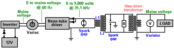
This simplified circuit avoids the need for expensive capacitors and the constraints of their voltage ratings, and the need for electronic control of the output frequency. The wire length in the turns of coil "L2" still needs to be exactly four times the wire length of the turns in coil "L1", but there is only one component which needs to be introduced, and that is the resistor "R" placed across the primary winding of the step-down isolation transformer. This transformer is a laminated iron-core type, suitable for the low mains frequency, but the output from "L2" is at much higher frequency. It is possible to pull the frequency down to suit the step-down transformer by connecting the correct value of resistor "R" across the output transformer (or a coil and resistor, or a coil and a capacitor). The value of resistor needed can be predicted from the American Radio Relay League graph (shown as Fig.44 in Don's pdf document which can be downloaded using http://www.free-energy-info.com/Smith.pdf). The sixth edition of the Howard Sams book "Handbook of Electronics Tables and Formulas" (ISBN-10: 0672224690 or ISBN-13: 978-0672224690) has a table which goes down to 1 kHz and so does not need to be extended to reach the frequencies used here. The correct resistor value could also be found by experimentation. You will notice that an earthed dual spark gap has been placed across "L2" in order to make sure that the voltage levels always stay within the design range.
Don also explains an even more simple version which does not need a Variac, high voltage capacitors or high voltage diodes. Here, a DC output is accepted which means that high-frequency step-down transformer operation can be used. This calls for an air-core transformer which you would wind yourself from heavy duty wire. Mains loads would then be powered by using a standard off-the-shelf inverter. In this version, it is of course, necessary to make the "L1" turns wire length exactly one quarter of the "L2" turns wire length in order to make the two coils resonate together. The operating frequency of each of these coils is imposed on them by the output frequency of the neon-tube driver circuit. That frequency is maintained throughout the entire circuit until it is rectified by the four diodes feeding the low-voltage storage capacitor. The target output voltage will be either just over 12 volts or just over 24 volts, depending on the voltage rating of the inverter which is to be driven by the system. The circuit diagram is:
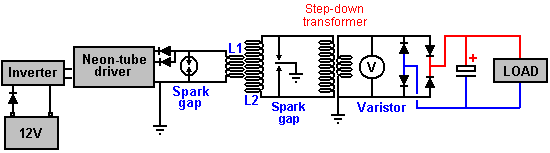
As many people will find the nomograph chart in Don's pdf document very difficult to understand and use, here is an easier version:

The objective here is to determine the "reactance" or 'AC resistance' in ohms and the way to do that is as follows:
Suppose that your neon-tube driver is running at 30 kHz and you are using a capacitor of 100 nF (which is the same as 0.1 microfarad) and you want to know what is the AC resistance of your capacitor is at that frequency. Also, what coil inductance would have that same AC resistance. Then the procedure for finding that out is as follows:
Draw a straight line from your 30 kHz frequency (purple line) through your 100 nanofarad capacitor value and carry the line on as far as the (blue) inductance line as shown above.
You can now read the reactance ("AC resistance") off the red line, which looks like 51 ohms to me. This means that when the circuit is running at a frequency of 30 kHz, then the current flow through your 100 nF capacitor will be the same as through a 51 ohm resistor. Reading off the blue "Inductance" line that same current flow at that frequency would occur with a coil which has an inductance of 0.28 millihenries.
I have recently been passed a copy of Don’s circuit diagram for this device, and it is shown here:
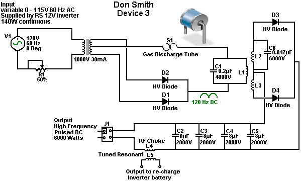
The 4000V 30mA transformer shown in this circuit diagram, may use a ferrite-cored transformer from a neon-tube driver module which steps up the voltage but it does not raise the frequency as that is clearly marked at 120 Hz pulsed DC. You will notice that this circuit diagram is drawn with Plus shown below Minus (which is most unusual).
Please note that when an earth connection is mentioned in connection with Don Smith's devices, we are talking about an actual wire connection to a metal object physically buried in the ground, whether it is a long copper rod driven into the ground, or an old car radiator buried in a hole like Tariel Kapanadze used, or a buried metal plate. When Thomas Henry Moray performed his requested demonstration deep in the countryside at a location chosen by the sceptics, the light bulbs which formed his demonstration electrical load, glowed more brightly with each hammer stroke as a length of gas pipe was hammered into the ground to form his earth connection.
Don also explains an even more simple version of his main device. This version does not need a Variac (variable voltage transformer) or high voltage capacitors. Here, a DC output is accepted which means that high-frequency step-down transformer operation can be used. This calls on the output side, for an air-core (or ferrite rod core) transformer which you would wind yourself from heavy duty wire. Mains loads would then be powered by using a standard off-the-shelf inverter. In this version, it is of course, very helpful to make the "L1" turns wire length exactly one quarter of the "L2" turns wire length in order to make the two coils automatically resonate together. The operating frequency of each of these coils is imposed on them by the output frequency of the neon-tube driver circuit. That frequency is maintained throughout the entire circuit until it is rectified by the four diodes feeding the low-voltage storage capacitor. The target output voltage will be either just over 12 volts or just over 24 volts, depending on the voltage rating of the inverter which is to be driven by the system.
As the circuit is capable of picking up additional magnetic pulses, such as those generated by other equipment, nearby lightning strikes, etc. an electronic component called a "varistor" marked "V" in the diagram, is connected across the load. This device acts as a voltage spike suppressor as it short-circuits any voltage above its design voltage, protecting the load from power surges. A Gas-Discharge Tube is an effective alternative to a varistor.
This circuit is effectively two Tesla Coils back-to-back and the circuit diagram might be:
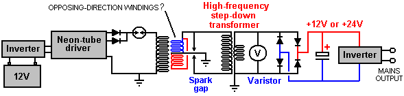
It is by no means certain that in this circuit, the red and blue windings are wound in opposing directions. The spark gap (or gas-discharge tube) in series with the primary of the first transformer alters the operation in a somewhat unpredictable way as it causes the primary to oscillate at a frequency determined by it’s inductance and it’s self-capacitance, and that may result in megahertz frequencies. The secondary winding(s) of that transformer must resonate with the primary and in this circuit which has no frequency-compensating capacitors, that resonance is being produced by the exact wire length in the turns of the secondary. This looks like a simple circuit, but it is anything but that. The excess energy is produced by the raised frequency, the raised voltage, and the very sharp pulsing produced by the spark. That part is straightforward. The remainder of the circuit is likely to be very difficult to get resonating as it needs to be in order to deliver that excess energy to the output inverter.
When considering the “length” of wire in a resonant coil, it is necessary to pay attention to the standing wave created under those conditions. The wave is caused by reflection of the signal when it reaches the end of the wire OR when there is a sudden change in the diameter of the wire as that changes the signal reflection ability at that point in the connection. You should pay attention to Richard Quick’s very clear description of this in the section of his patent which is included later on in this chapter. Also, remember what Don Smith said about locating the peaks of the standing wave by using a hand-held neon lamp.
One very significant thing which Don pointed out is that the mains electricity available through the wall socket in my home, does not come along the wires from the generating station. Instead, the power station influences a local ‘sub-station’ and the electrons which flow through my equipment actually come from my local environment because of the influence of my local sub-station. Therefore, if I can create a similar influence in my home, then I no longer need that sub-station and can have as much electrical energy as I want, without having to pay somebody else to provide that influence for me.
A Practical
Implementation of one of Don Smith’s Designs
The objective here, is to determine how
to construct a self-powered, free-energy electrical generator which has no
moving parts, is not too expensive to build, uses readily available parts and
which has an output of some kilowatts.
However, under no circumstances should this document be considered to be
an encouragement for you, or anyone else to actually build one of these
devices. This document is presented
solely for information and educational purposes, and as high voltages are
involved, it should be considered to be a dangerous device unsuited to being
built by inexperienced amateurs. The
following section is just my opinions and so should not be taken as tried and
tested, working technology, but instead, just the opinion of an inexperienced
writer.
However, questions from several different
readers indicate that a short, reasonably specific description of the steps
needed to attempt a replication of a Don Smith device would be helpful. Again, this document must not be considered
to be a recommendation that you actually build one of these high-voltage,
potentially dangerous devices. This is
just information intended to help you understand what I believe is involved in
this process.
In broad outline, the following
steps are used in the most simple version of the arrangement:
1. The very low frequency and
voltage of the local mains supply is discarded in favour of an electrical
supply which operates at more than 20,000 Hz (cycles per second) and has a
voltage of anything from 350 volts to 10,000 volts. The higher voltages can give greater overall
output power, but they involve greater effort in getting the voltage back down
again to the level of the local mains voltage in order for standard mains
equipment to be used.
2. This high-frequency high voltage
is used to create a series of very rapid sparks using a spark gap which is
connected to a ground connection.
Properly done, the spark frequency is so high that there is no audible
sound caused by the sparks. Each spark
causes a flow of energy from the local environment into the circuit. This energy is not standard electricity which
makes things hot when current flows through them, but instead this energy flow
causes things to become cold when the power flows through them, and so it is often
called “cold” electricity. It is tricky
to use this energy unless all you want to do is light up a series of light
bulbs (which incidentally, give out a different quality of light when powered
with this energy). Surprisingly, the
circuit now contains substantially more power than the amount of power needed
to produce the sparks. This is because
additional energy flows in from the ground as well as from the local
environment. If you have conventional
training and have been fed the myth of “closed systems”, then this will seem
impossible to you. So, let me ask you
the question: if, as can be shown, all of the electricity flowing into the
primary winding of a transformer, flows back out of that winding, then where
does the massive, continuous flow of electricity coming from the secondary winding
come from? None of it comes from the
primary circuit and yet millions of electrons flow out of the secondary in a
continuous stream which can be supplied indefinitely. So, where do these electrons come from? The answer is ‘from the surrounding local
environment which is seething with excess energy’ but your textbooks won’t like
that fact as they believe that the transformer circuit is a ‘closed system’ –
something which probably can’t be found anywhere in this universe.
3. This high-voltage, high-frequency,
high-power energy needs to be converted to the same sort of hot electricity
which comes out of a mains wall socket at the local voltage and frequency. This is where skill and understanding come
into play. The first step is to lower
the voltage and increase the available current with a step-down resonant
transformer. This sounds highly
technical and complicated, and looking at Don Smith’s expensive Barker &
Williamson coil, makes the whole operation appear to be one for rich
experimenters only. This is not the case
and a working solution can be cheap and easy.
It is generally not convenient to get the very high voltage all the way
down to convenient levels in a single step, and so, one or more of those
resonant transformers can be used to reach the target voltage level. Each step down transformer boosts the
available current higher and higher.
4. When a satisfactory voltage has
been reached, we need to deal with the very high frequency. The easiest way to deal with it is to use
high-speed diodes to convert it to pulsing DC and feed that into a capacitor to
create what is essentially, an everlasting battery. Feeding this energy into a capacitor converts
it into conventional “hot” electricity and a standard off-the-shelf inverter
can be used to give the exact voltage and frequency of the local mains
supply. In most of the world, that is
220 volts at 50 cycles per second. In
So, let’s take a look at each of
these step in more detail and see if we can understand what is involved and
what our options are:
1. We want to produce a
high-voltage, high-frequency, low-current power source. Don Smith shows a Neon-Sign Transformer
module. His module produced a voltage
which was higher than was convenient and so he used a variable AC transformer
or “Variac” as it is commonly known, to lower the input voltage and so, lower
the output voltage. There is actually no
need for a Variac as we can handle the higher voltage or alternatively, use a
more suitable Neon-Sign Transformer module.
However, we have a problem with
using that technique. In the years since
Don bought his module, they have been redesigned to include circuitry which
disables the module if any current flows out of it directly to earth, and as
that is exactly what we would want to use it for, so most, if not all of the
currently available neon-sign transformer modules are not suitable for our
needs. However, I’m told that if the
module has an earth wire and that earth wire is left unconnected, that it
disables the earth-leakage circuitry, allowing the unit to be used in a Don
Smith circuit. Personally, I would not
recommend that if the module is enclosed in a metal housing.
A much cheaper alternative is shown
here: http://www.youtube.com/watch?v=RDDRe_4D93Q
where a small plasma globe circuit is used to generate a high-frequency
spark. It seems highly likely that one
of those modules would suit our needs:
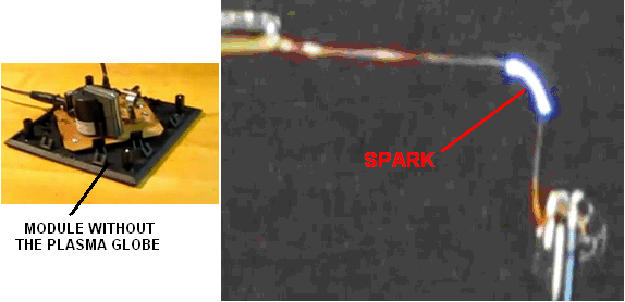
An alternative method is to build
your own power supply from scratch.
Doing that is not particularly difficult and if you do not understand
any electronics, then perhaps, reading the beginner’s electronics tutorial in
chapter 12 (http://www.free-energy-info.com/Chapter12.pdf)
will fill you in on all of the basics needed for understanding (and probably
designing your own) circuits of this type.
Here is a variable frequency design for home-construction:
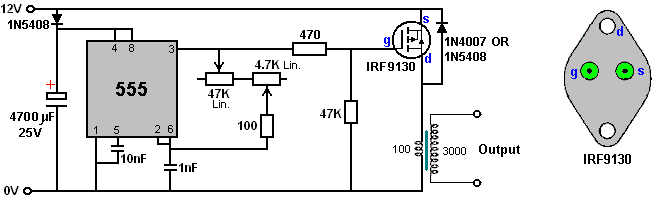
One advantage of this circuit is that the output transformer is driven at the frequency set by the 555 timer and that frequency is not affected by the number of turns in the primary winding, nor it’s inductance, wire diameter, or anything else to do with the coil. While this circuit shows the rather expensive IRF9130 transistor, I expect that other P-channel FETs would work satisfactorily in this circuit. The IRF9130 transistor looks like this:
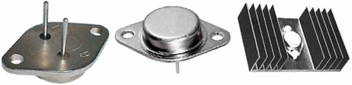
The circuit has a power supply diode and capacitor, ready to receive energy from the output at some later date if that is possible and desired. The 555 circuit is standard, giving a 50% Mark/Space ratio. The 10 nF capacitor is there to maintain the stability of the 555 and the timing section consists of two variable resistors, one fixed resistor and the 1 nF capacitor. This resistor arrangement gives a variable resistance of anything from 100 ohms to 51.8K and that allows a substantial frequency range. The 47K (Linear) variable resistor controls the main tuning and the 4.7K (Linear) variable resistor gives a more easily adjustable frequency for exact tuning. The 100 ohm resistor is there in case both of the variable resistors are set to zero resistance. The output is fed through a 470 ohm resistor to the gate of a very powerful P-channel FET transistor which drives the primary winding of the output transformer.
The output transformer can be wound on an insulating spool covering a ferrite rod, giving both good coupling between the windings, and high-frequency operation as well. The turns ratio is set to just 30:1 due to the high number of primary winding turns. With a 12-volt supply, this will give a 360-volt output waveform, and by reducing the primary turns progressively, allows the output voltage to be increased in controlled steps. With 10 turns in the primary, the output voltage should be 3,600 volts and with just 5 turns 7,200 volts. The higher the voltage used, the greater the amount of work needed later on to get the voltage back down to the output level which we want.
Looking at the wire specification table, indicates that quite a small wire diameter could be used for the oscillator output transformer’s secondary winding. While this is perfectly true, it is not the whole story. Neon Tube Drivers are very small and the wire in their output windings is very small diameter indeed. Those driver modules are very prone to failure. If the insulation on any one turn of the winding fails and one turn becomes a short-circuit, then that stops the winding from oscillating, and a replacement is needed. As there are no particular size constraints for this project, it might be a good idea to use enamelled copper wire of 0.45 mm or larger in an attempt to avoid this insulation failure hazard. No part of the transformer coil spool should be metal and it would not be any harm to cover each layer of secondary winding with a layer of electrical tape to provide additional insulation between the coil turns in one layer and the turns in the layer on top of it.
A plug-in board layout might be:
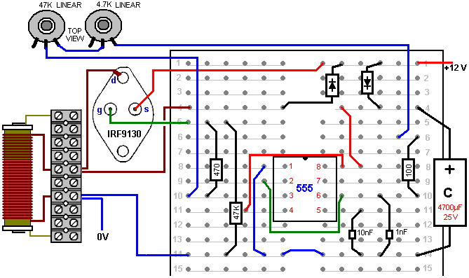
Please remember that you can’t just stick your average voltmeter across a 4 kV capacitor (unless you really do want to buy another meter) as they only measure up to about a thousand volts DC. So, if you are using high voltage, then you need to use a resistor-divider pair and measure the voltage on the lower resistor. But what resistor values should you use? If you put a 10 Megohm resistor across your 4 kV charged capacitor, the current flowing through the resistor would be 0.4 milliamps. Sounds tiny, doesn’t it? But that 0.4 mA is 1.6 watts which is a good deal more than the wattage which your resistor can handle. Even using this arrangement:
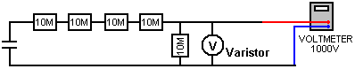
the current will be 0.08 mA and the
wattage per resistor will be 64 mW. The
meter reading will be about 20% of the capacitor voltage which will give a
voltmeter reading of 800 volts. The
input resistance of the meter needs to be checked and possibly, allowed for as
the resistance in this circuit is so high (see chapter 12). When making a measurement of this type, the
capacitor is discharged, the resistor chain and meter attached, and then, and
only then, is the circuit powered up, the reading taken, the input power
disconnected, the capacitor discharged, and the resistors disconnected. High-voltage circuits are highly dangerous,
especially so, where a capacitor is involved.
The recommendation to wear thick rubber gloves for this kind of work, is
not intended to be humorous. Circuits of
this type are liable to generate unexpected high-voltage spikes, and so, it
might be a good idea to connect a varistor across the meter to protect it from
those spikes. The varistor need to be
set to the voltage which you intend to measure and as varistors may not be
available above a 300V threshold, two or more may need to be connected in series
where just one is shown in the diagram above.
The varistor should not have a higher voltage rating than your meter.
2. We now need to use this high
voltage to create a strategically positioned spark to a ground connection. When making an earth connection, it is
sometimes suggested that connecting to water pipes or radiators is a good idea
as they have long lengths of metal piping running under the ground and making
excellent contact with it. However, it
has become very common for metal piping to be replaced with cheaper plastic
piping and so any proposed pipe connection needs a check to ensure that that
there is metal piping which runs all the way into the ground.
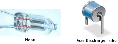
The spark gaps shown can be
commercial high-voltage gas discharge tubes, adjustable home-made spark gaps with
stainless steel tips about 1 mm apart, car spark plugs, or standard neon bulbs,
although these run rather hot in this application. A 15 mm x 6 mm size neon bulb operates with
only 90 or 100 volts across it, it would take a considerable number of them
connected in series to create a high voltage spark gap, but it is probably a
misconception that the spark gap itself needs a high voltage. Later on in this chapter, there is an example
of a very successful system where just one neon bulb is used for the spark gap
and an oscillating magnetic field more than a meter wide is created when driven
by just an old 2,500 volt neon-sign transformer module. If using a neon bulb for the spark gap, then
an experienced developer recommends that a 22K resistor is used in series with
the neon in order to extend it’s working life very considerably.
This circuit is one way to connect
the spark gap and ground connection:
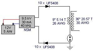
This is an adaption of a circuit
arrangement used by the forum member “SLOW-‘N-EASY” on the Don Smith topic in
the energeticforum. Here, he is using a
‘LowGlow’ neon transformer intended for use on a bicycle. The diodes are there to protect the
high-voltage power supply from any unexpected voltage spikes created later on
in the circuit. The spark gap is
connected between the primary winding of a step-up transformer and the earth
connection. No capacitor is used. Seeing this circuit, we immediately think of
Don Smith’s large and expensive coils, but this experimenter does not use
anything like that. Instead, he winds
his transformer on a simple plastic former like this:
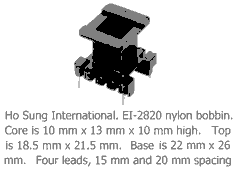
And to make matters ‘worse’ the primary
winding wire is just 9 inches (228.6 mm) long and the secondary just 36 inches
(914.4 mm) long, the primary being wound directly on top of the secondary. Not exactly a large or expensive construction
and yet one which appears to perform adequately in actual tests.
This is a very compact form of construction,
but there is no necessity to use exactly the same former for coils, nor is
there anything magic about the nine-inch length of the L1 coil, as it could
easily be any convenient length, say two feet or 0.5 metres, or whatever. The important thing is to make the L2 wire
length exactly four times that length, cutting the lengths accurately. It is common practice to match the weight of
copper in each coil and so the shorter wire is usually twice the diameter of
the longer wire.
The circuit above, produces a cold
electricity output of high voltage and high frequency. The voltage will not be the same as the neon
transformer voltage, nor is the frequency the same either. The two coils resonate at their own natural
frequency, unaltered by any capacitors.
3. The next step is to get the high voltage
down to a more convenient level, perhaps, like this:
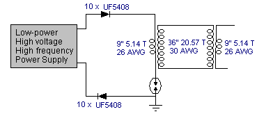
Here, an identical transformer, wound in
exactly the same way, is used in reverse, to start the voltage lowering
sequence. The wire length ratio is
maintained to keep the transformer windings resonant with each other.
Supposing we were to wind the L2 coil of
this second transformer in a single straight winding and instead of winding
just one L1 winding on top of it, two or more L1 identical windings were placed
on top of it – what would happen?:
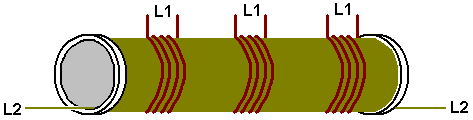
Now for a comment which will seem heretical
to people steeped in the present day (inadequate) level of technology. The power flowing in these transformers is
cold electricity which operates in an entirely different way to hot electricity. The coupling between these coils would be
inductive if they were carrying hot electricity and in that case, any
additional power take-off from additional L1 coils would have to be ‘paid’ for
by additional current draw through the L2 coil.
However, with the cold electricity which these coils are actually
carrying, the coupling between the coils is magnetic and not inductive and that
results in no increase in L2 current, no matter how many L1 coil take-offs
there are. Any additional L1 coils will
be powered for free. However, the
position of the coils relative to each other has an effect on the tuning, so
the L1 coil should be in the middle of the L2 coil, which means that any
additional L1 coils are going to be slightly off the optimum tuning point.
4. Anyway, following through
on just one L1 coil, there is likely to be at least one further step-down
transformer needed and eventually, we need conversion to hot electricity:
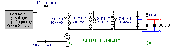
Probably the easiest conversion is by
feeding the energy into a capacitor and making it standard DC. The frequency is still very high, so
high-speed diodes (such as the 75-nanosecond UF54008) are needed here although
the voltage level is now low enough to be no problem. The DC output can be used to power an
inverter so that standard mains equipment can be used. It is not necessary to use just one
(expensive) large-capacity inverter to power all possible loads as it is
cheaper to have several smaller inverters, each powering it’s own set of
equipment. Most equipment will run satisfactorily
on square-wave inverters and that includes a mains unit for powering the input
oscillator circuit.
PVC pipe is not a great material when using high-frequency high-voltage signals, and grey PVC pipe is a particularly poor coil former material. The much more expensive acrylic pipe is excellent, but if using PVC, then performance will be better if the PVC pipe is coated with an insulating lacquer (or table tennis balls dissolved in acetone as show on YouTube).
However, there are some other factors which have not been mentioned. For example, if the L1 coil is wound directly on top of the L2 coil, it will have roughly the same diameter and so, the wire being four times longer, will have roughly four times as many turns, giving a step-up or step-down ratio of around 4:1. If, on the other hand, the coil diameters were different, the ratio would be different as the wire lengths are fixed relative to each other. If the L2 coil were half the diameter of the L1 coil, then the turns ratio would be about 8:1 and at one third diameter, 12:1 and at a quarter diameter 16:1 which means that a much greater effect could be had from the same wire length by reducing the L2 coil diameter. However, the magnetic effect produced by a coil is linked to the cross-sectional area of the coil and so a small diameter is not necessarily at great advantage. Also, the length of the L1 coil wire and number of turns in it, affect the DC resistance, and more importantly, the AC impedance which affects the amount of power needed to pulse the coil.
It is also thought that having the same weight of copper in each winding gives an improved performance, but what is not often mentioned is the opinion that the greater the weight of copper, the greater the effect. You will recall that Joseph Newman (chapter 11) uses large amounts of copper wire to produce remarkable effects. So, while 9 inches and 36 inches of wire will work for L1 and L2, there may well be improved performance from longer lengths of wire and/or thicker wires.
We should also not forget that Don Smith pointed out that voltage and current act (out of phase and) in opposite directions along the L2 coil, moving away from the L1 coil:
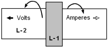
It has been suggested that a greater and more effective power output can be obtained by splitting the L2 coil underneath the L1 coil position, winding the second part of L2 in the opposite direction and grounding the junction of the two L2 windings. Don doesn’t consider it necessary to reverse the direction of winding. The result is an L2 winding which is twice as long as before and arranged like this:
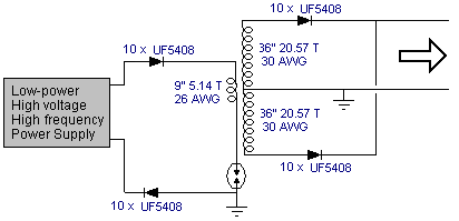
Here, the additional high-voltage diodes allow the two out of phase windings to be connected across each other.
You will notice that this arrangement calls for two separate earth connections, both of which need to be high-quality connections, something like a pipe or rod driven deeply into moist soil or alternatively, a metal plate or similar metal object of substantial surface area, buried deep in moist earth, and a thick copper wire or copper braid used to make the connection. These earthing points need to be fairly far apart, say, ten metres. A single earth connection can’t be used as that would effectively short-circuit across the L1/L2 transformer which you really do not want to do.
With this arrangement, the outline circuit becomes:
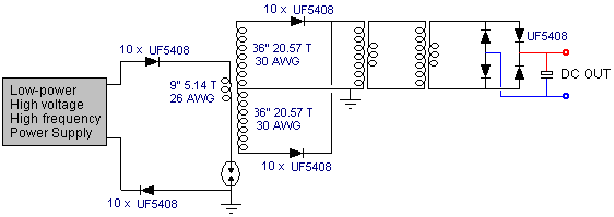
The thick earth wiring is helpful because in order to avoid the earth wire being included in the resonant wire length, you need a sudden change in wire cross-section:
These are just some ideas which might be considered by some experienced developer who may be thinking of investigating Don Smith style circuitry.
To give you some idea of the capacity of some commercially available wires when carrying hot electricity, this table may help:
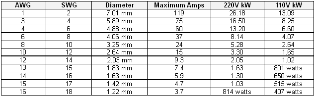
It is recommended that the wire have a current carrying capacity of 20% more than the expected actual load, so that it does not get very hot when in use. The wire diameters do not include the insulation, although for solid enamelled copper wire, that can be ignored.
There is a most impressive video and circuit shown at http://youtu.be/Q3vr6qmOwLw where a very simple arrangement produces an immediately successful performance for the front end of Don’s circuitry. The circuit appears to be:
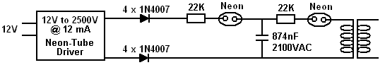
Here, a simple Neon Sign Transformer module which has no earth connection, is used to produce a 2.5 kV voltage with a frequency of 25 kHz and a maximum output current capacity of 12 mA. There is no difficulty in constructing the equivalent to that power supply unit. The two outputs from the module are converted to DC by a chain of four 1N4007 diodes in series in each of the two outputs (each chain being inside a plastic tube for insulation).
This output is fed through an optional 22K resistor via a neon lamp to a microwave oven capacitor which happens to be 874 nF with a voltage rating of 2,100 volts. You might feel that the voltage rating of the capacitor is too low for the output voltage of the neon sign module, but the neon has a striking voltage of just 90 volts and so the capacitor is not going to reach the output voltage of the power supply. The resistors are solely to extend the life of the neons as the gas inside the tube gets a considerable jolt in the first nanosecond after switch-on. It is unlikely that omitting those resistors would have any significant effect, but then, including them is a trivial matter. The second neon feeds the primary of the resonant transformer which is only shown in notional outline in the diagram above as the developer suggests that the primary acts as a transmitter and that any number of receiving coils can be used as individual secondaries by being tuned to the exact frequency of that resonating primary.
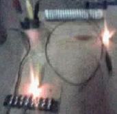
In the video
showing this arrangement, the developer demonstrates the fluctuating,
high-frequency field which extends for some four feet (1.2 m) around the
coil. He also remarks that the single
neons in his arrangement could each be replaced with two neons in series. In test which I ran, I found that I needed
two neons in series ahead of the capacitor in order to get continuous lighting
of the output neon. Also, one of the
diodes needed to be reversed so that one faced towards the input and one away
from it. It did not matter which diode
was reversed as both configurations worked.
Again, please note that this presentation is for information purposes
only and it is NOT a recommendation
that you should actually build one of these devices. Let me stress again that this is a
high-voltage device made even more dangerous by the inclusion of a capacitor,
and it is quite capable of killing you, so, don’t build one. The developer suggests that it is an
implementation of the “transmitter” section of Don’s Transmitter/multiple-receivers
design shown below. However, before
looking at that design, there is one question which causes a good deal of
discussion on the forums, namely, if the centre-tap of the L2 secondary coil is
connected to ground, then should that earth-connection wire length be
considered to be part of the quarter length of the L1 coil? To examine this possibility in depth, the
following quote from Richard Quick’s very clear explanation of resonance in his
However, the simple answer is that for there to be exact resonance between two lengths of wire (whether or not part, or all of those lengths of wire happen to be wound into a coil), then one length needs to be exactly four times as long as the other, and ideally, half the diameter as well. At both ends of both lengths of wire, there needs to be a sudden change in wire diameter and Richard explains why this is. But, leaving that detailed explanation for now, we can use that knowledge to explain the above simplified system in more detail. Here is the circuit again:
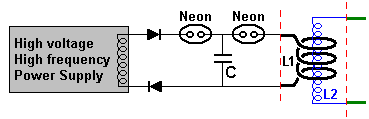
One very important point to note is that no earth connection is required and in spite of that, the performance shown on video is very impressive. While an earth connection can feed substantial power into the circuit, not needing one for the front end is an enormous advantage and potentially, opens the way for a truly portable device. Another very important point is the utter simplicity of the arrangement where only cheap, readily available components are used (and not many of those are needed). The resistors for extending the life of the neon bulbs are not shown, but they can be included if desired and the circuit operation is not altered significantly by having them there. If a higher spark voltage is wanted, then two or more neon bulbs can be used in series where these circuit diagrams show just one.
A point to note is that the lower diode is shown reversed when compared to the previous diagram. This is because the power supply shown is any generic power supply which drives a simple output coil which does not have a centre tap. The neon supply of the earlier diagram appears to have two separate outputs which will, presumably, be out of phase with each other as that is common practice for neon-sign driver modules. If you wish, the two diodes shown here could be replaced by a diode bridge of four high-voltage, high-speed diodes.
The wire lengths of L1 and L2 are measured very accurately from where the wire diameter changes suddenly, as indicated by the red dashed lines. The L2 wire length is exactly four times as long as the L1 wire length and the L2 wire diameter is half of the L1 wire diameter.
How long is the L1 wire? Well, how long would you like it to be? It can be whatever length you want and the radius of the L1 coil can be whatever you want it to be. The theory experts will say that the L1 coil should resonate at the frequency of the power feeding it. Well, good for them, I say, so please tell me what frequency that is. It is not going to be the frequency of the power supply as that will be changed by at least one of the neon bulbs. So, what frequency will the neon bulb produce? Not even the manufacturer could tell you that as there is quite a variation between individual bulbs which are supposedly identical.
Actually, it doesn’t matter at all, because the L1 coil (and the L2 coil if you measure them accurately) has a resonant frequency all of its own and it will vibrate at that frequency no matter what the frequency feeding it happens to be. A coil resonates in very much the same way that a bell rings when it is struck. It doesn’t matter how hard you strike the bell or how rapidly you strike it – the bell will ring at it’s own natural frequency. So the L1 coil will resonate at it’s own natural frequency no matter what rate the voltage spikes striking it arrive, and as the L2 coil has been carefully constructed to have exactly that same frequency, it will resonate in synchronisation with the L1 coil.
This means that the length of the wire for the L1 coil is the choice of the builder, but once that length is chosen it determines the length of the wire for the L2 coil as that is exactly four times as long, unless the builder decides to use an arrangement which has L2 wound in both the Clockwise and counter-clockwise directions, in which case, each half of the L2 coil will be four times the length of the wire in the L1 coil, like this:
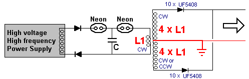
Mind you, there is one other factor to be considered when deciding what the most convenient wire length for L1 might be, and that is the number of turns in the L1 coil. The larger the ratio between the turns in L1 and the turns in L2, the higher the voltage boost produced by the L1/L2 transformer, and remember that the length of L2 is fixed relative to the length of L1.
So, a possible circuit style might be:
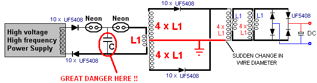
There are some important points to remember. One is that there must be a sudden change of wire diameter at both ends of each L1 coil and at the ends of each L2 coil. If there isn’t, then the connecting wire length will form part of the coil and if there is some change in diameter but not very much, then it is anybody’s guess what the resonant wire length for that coil will be. There can be as many step-down isolation air-core L1/L2 transformers as desired and these do not need to be particularly large or expensive.
The builder of this circuit put it together in just a few minutes, using components which were to hand, including the microwave oven capacitor marked “C” in the diagrams above. That capacitor is isolated on both sides by the neon bulb spark gaps and so it will have no modifying effect on the resonant frequency of any of the coils in this circuit. But it is vital to understand that the energy stored in that capacitor can, and will, kill you instantly if you were to touch it, so let me stress once again that this information is NOT a recommendation that you actually build this circuit. The DC output from the circuit is intended to power a standard inverter, which in turn, would be perfectly capable of powering the high voltage, high frequency input oscillator.
One final point is that as demonstrated in the video, the oscillating magnetic field produced by the L1 coil can power several identical L2 coils, giving several additional power outputs for no increase in input power, because the coupling is magnetic and not inductive as mentioned earlier in this chapter. Please notice that neither the L1 coil nor the L2 coil has a capacitor connected across it, so resonance is due solely to wire length and no expensive high-voltage capacitors are needed to get every L1/L2 coil pair resonating together. One possible arrangement might be like this:
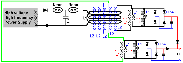
Where two of the L2 coils are shown connected together to give increased output power. This arrangement uses low-voltage inexpensive components for the output stages and there is no obvious limit to the amount of output power which could be provided. As the circuit operates at high frequency throughout, there is no particular need for additional L2 coils to be placed physically inside the L1 coil:
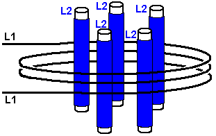
However, there can be an advantage to this arrangement in that the wire length of the L1 coil is greater, which in turn makes the wire length of each L2 coil greater (being four times longer). This gives greater flexibility when planning the turns ratio of the L1/L2 transformer. The voltage step-up or step-down of that transformer happens to be in the ratio of the turns, in spite of the fact that this is not inductive coupling and so standard transformer technology does not apply.
When you choose the number of turns and coil diameter for L1, that also gives the length of the L2 wire. In order to get the desired output voltage, if perhaps, the step-down ratio is needed to be an amount of 46:1, then you need 46 times the number of L1 turns on the L2 coil. That means that you know both the wire length and number of turns wanted in the L2 coil. But, as each turn will have a length of 3.14159 times the diameter, it follows then that the wanted diameter is the wire length per turn, divided by 3.14159. The wire sits on top of the tube on which it is wound and so has a greater diameter by one wire thickness, so the calculated tube diameter needs to be reduced by one wire diameter. For example, if the length per turn is 162 mm and the wire diameter 0.8 mm, then the tube diameter would be 162 / 3.14159 – 0.8 which is 50.766 mm (just over two inches).
So, if we have resonant standing-wave voltages in our L2 coil and some of that signal passes through the wire connecting one end of the coil to the earth, then what will happen? The best way to check it is to test the way which a prototype behaves, however, if I may express an opinion, I would suggest that the signal passing down the earth wire will be absorbed when it reaches the earth and that will prevent the signal being reflected back to the L2 coil to upset it’s operation.
Another device of Don's is particularly attractive because almost no home-construction is needed, all of the components being available commercially, and the output power being adaptable to any level which you want. Don particularly likes this circuit because it demonstrates COP>1 so neatly and he remarks that the central transmitter Tesla Coil on its own is sufficient to power a household.
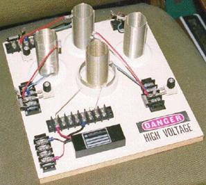
The coil in the centre of the board is a power transmitter made from a Tesla Coil constructed from two Barker & Williamson ready-made coils. Three more of the inner coil are also used as power receivers. The outer, larger diameter coil is a few turns taken from one of their standard coils and organised so that the coil wire length is one quarter of the coil wire length of the inner coil ("L2").
As before, a commercial neon-tube driver module is used to power the "L1" outer coil with high voltage and high frequency. It should be understood that as power is drawn from the local environment each time the power driving the transmitter coil "L1" cycles, that the power available is very much higher at higher frequencies. The power at mains frequency of less than 100 Hz is far, far less than the power available at 35,000 Hz, so if faced with the choice of buying a 25 kHz neon-tube driver module or a 35 kHz module, then the 35 kHz module is likely to give a much better output power at every voltage level.
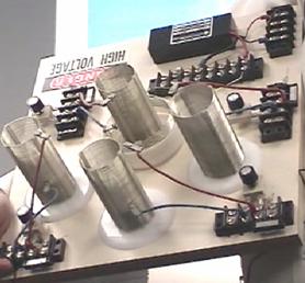
The "L1" short outer coil is held in a raised position by the section of white plastic pipe in order to position it correctly relative to the smaller diameter "L2" secondary coil.
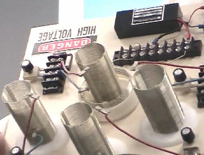
The secondary coils are constructed using Barker & Williamson's normal method of using slotted strips to hold the tinned, solid copper wire turns in place.
As there are very slight differences in the manufactured coils, each one is tuned to the exact transmitter frequency and a miniature neon is used to show when the tuning has been set correctly.
The key feature of this device is the fact that any number of receiver coils can be placed near the transmitter and each will receive a full electrical pick up from the local environment, without altering the power needed to drive the Tesla Coil transmitter - more and more output without increasing the input power - unlimited COP values, all of which are over 1. The extra power is flowing in from the local environment where there is almost unlimited amounts of excess energy and that inflow is caused by the rapidly vibrating magnetic field generated by the central Tesla Coil. While the additional coils appear to just be scattered around the base board, this is not the case. The YouTube video http://www.youtube.com/watch?v=TiNEHZRm4z4&feature=related demonstrates that the pick-up of these coils is affected to a major degree by the distance from the radiating magnetic field. This is to do with the wavelength of the signal driving the Tesla Coil, so the coils shown above are all positioned at exactly the same distance from the Tesla Coil. You still can have as many pick-up coils as you want, but they will be mounted in rings around the Tesla Coil and the coils in each ring will be at the same distance from the Tesla Coil in the centre.
Each of the pick up coils act exactly the same as the "L2" secondary coil of the Tesla Coil transmitter, each picking up the same level of power. Just as with the actual "L2" coil, each will need an output circuit arrangement as described for the previous device. Presumably, the coil outputs could be connected in parallel to increase the output amperage, as they are all resonating at the same frequency and in phase with each other. Each will have its own separate output circuit with a step-down isolation transformer and frequency adjustment as before. If any output is to be a rectified DC output, then no frequency adjustment is needed, just rectifier diodes and a smoothing capacitor following the step-down transformer which will need to be an air core or ferrite core type due to the high frequency. High voltage capacitors are very expensive. The http://www.richieburnett.co.uk/parts.html web site shows various ways of making your own high-voltage capacitors and the advantages and disadvantages of each type.
There are two practical points which need to be mentioned. Firstly, as the Don Smith devices shown above feed radio frequency waveforms to coils which transmit those signals, it may be necessary to enclose the device in an earthed metal container in order not to transmit illegal radio signals. Secondly, as it can be difficult to obtain high-voltage high-current diodes, they can be constructed from several lower power diodes. To increase the voltage rating, diodes can be wired in a chain. Suitable diodes are available as repair items for microwave ovens. These typically have about 4,000 volt ratings and can carry a good level of current. As there will be minor manufacturing differences in the diodes, it is good practice to connect a high value resistor (in the 1 to 10 megohm range) across each diode as that ensures that there is a roughly equal voltage drop across each of the diodes:
![]()
If the diode rating of these diodes were 4 amps at 4,000 volts, then the chain of five could handle 4 amps at 20,000 volts. The current capacity can be increased by connecting two or more chains in parallel. Most constructors omit the resistors and find that they seem to get satisfactory performance.
The impedance of a coil depends on it’s size, shape, method of winding, number of turns and core material. It also depends on the frequency of the AC voltage being applied to it. If the core is made up of iron or steel, usually thin layers of iron which are insulated from each other, then it can only handle low frequencies. You can forget about trying to pass 10,000 cycles per second (“Hz”) through the coil as the core just can’t change it’s magnetic poles fast enough to cope with that frequency. A core of that type is ok for the very low 50 Hz or 60 Hz frequencies used for mains power, which are kept that low so that electric motors can use it.
For higher frequencies, ferrite can be used for a core and that is why some portable radios use ferrite-rod aerials, which are a bar of ferrite with a coil wound on it. For higher frequencies (or higher efficiencies) iron dust encapsulated in epoxy resin is used. An alternative is to not use any core material and that is usually referred to as an “air-core” coil. These are not limited in frequency by the core but they have a very much lower inductance for any given number of turns. The efficiency of the coil is called it’s “Q” (for “Quality”) and the higher the Q factor, the better. The resistance of the wire lowers the Q factor.
A coil has inductance, and resistance caused by the wire, and capacitance caused by the turns being near each other. However, having said that, the inductance is normally so much bigger than the other two components that we tend to ignore the other two. Something which may not be immediately obvious is that the impedance to AC current flow through the coil depends on how fast the voltage is changing. If the AC voltage applied to a coil completes one cycle every ten seconds, then the impedance will be much lower than if the voltage cycles a million times per second.
If you had to guess, you would think that the impedance would increase steadily as the AC frequency increased. In other words, a straight-line graph type of change. That is not the case. Due to a feature called resonance, there is one particular frequency at which the impedance of the coil increases massively. This is used in the tuning method for AM radio receivers. In the very early days when electronic components were hard to come by, variable coils were sometimes used for tuning. We still have variable coils today, generally for handling large currents rather than radio signals, and we call them “rheostats” and some look like this:
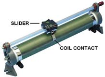
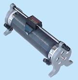
These have a coil of wire wound around a hollow former and a slider can be pushed along a bar, connecting the slider to different winds in the coil depending on it’s position along the supporting bar. The terminal connections are then made to the slider and to one end of the coil. The position of the slider effectively changes the number of turns of wire in the part of the coil which is being used in the circuit. Changing the number of turns in the coil, changes the resonant frequency of that coil. AC current finds it very, very hard to get through a coil which has the same resonant frequency as the AC current frequency. Because of this, it can be used as a radio signal tuner:
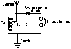
If the coil’s resonant frequency is changed to match that of a local radio station by sliding the contact along the coil, then that particular AC signal frequency from the radio transmitter finds it almost impossible to get through the coil and so it (and only it) diverts through the diode and headphones as it flows from the aerial wire to the earth wire and the radio station is heard in the headphones. If there are other radio signals coming down the aerial wire, then, because they are not at the resonant frequency of the coil, they flow freely through the coil and don’t go through the headphones.
This system was soon changed when variable capacitors became available as they are cheaper to make and they are more compact. So, instead of using a variable coil for tuning the radio signal, a variable capacitor connected across the tuning coil did the same job:
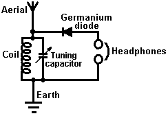
While the circuit diagram above is marked “Tuning capacitor” that is actually quite misleading. Yes, you tune the radio receiver by adjusting the setting of the variable capacitor, but, what the capacitor is doing is altering the resonant frequency of the coil/capacitor combination and it is the resonant frequency of that combination which is doing exactly the same job as the variable coil did on it’s own.
This draws attention to two very important facts concerning coil/capacitor combinations. When a capacitor is placed across a coil “in parallel” as shown in this radio receiver circuit, then the combination has a very high impedance (resistance to AC current flow) at the resonant frequency. But if the capacitor is placed “in series” with the coil, then there is nearly zero impedance at the resonant frequency of the combination:
![]()
This may seem like something which practical people would not bother with, after all, who really cares? However, it is a very practical point indeed. Remember that Don Smith often uses an early version, off-the-shelf neon-tube driver module as an easy way to provide a high-voltage, high-frequency AC current source, typically, 6,000 volts at 30,000 Hz. He then feeds that power into a Tesla Coil which is itself, a power amplifier. The arrangement is like this:
People who try to replicate Don’s designs tend to say “I get great sparks at the spark gap until I connect the L1 coil and then the sparks stop. This circuit can never work because the resistance of the coil is too low”.
If the resonant frequency of the L1 coil does not match the frequency being produced by the neon-tube driver circuit, then the low impedance of the L1 coil at that frequency, will definitely pull the voltage of the neon-tube driver down to a very low value. But if the L1 coil has the same resonant frequency as the driver circuit, then the L1 coil (or the L1 coil/capacitor combination shown on the right, will have a very high resistance to current flow through it and it will work well with the driver circuit. So, no sparks, means that the coil tuning is off. It is the same as tuning a radio receiver, get the tuning wrong and you don’t hear the radio station.
This is very nicely demonstrated using simple torch bulbs and two coils in the YouTube video showing good output for almost no input power: http://www.youtube.com/watch?v=kQdcwDCBoNY and while only one resonant pick-up coil is shown, there is the possibility of using many resonant pick-up coils with just the one transmitter.
With a coil (fancy name “inductor” and symbol “L”), AC operation is very different to DC operation. The coil has a DC resistance which can be measured with the ohms range of a multimeter, but that resistance does not apply when AC is being used as the AC current flow is not determined by the DC resistance of the coil. Because of this, a second term has to be used for the current-controlling factor of the coil, and the term chosen is “impedance” which is the feature of the coil which “impedes” AC current flow through the coil.
The impedance of a coil depends on it’s size, shape, method of winding, number of turns and core material. It also depends on the frequency of the AC voltage being applied to it. If the core is made up of iron or steel, usually thin layers of iron which are insulated from each other, then it can only handle low frequencies. You can forget about trying to pass 10,000 cycles per second (“Hz”) through the coil as the core just can’t change it’s magnetic poles fast enough to cope with that frequency. A core of that type is ok for the very low 50 Hz or 60 Hz frequencies used for mains power, which are kept that low so that electric motors can use it.
For higher frequencies, ferrite can be used for a core and that is why some portable radios use ferrite-rod aerials, which are a bar of ferrite with a coil wound on it. For higher frequencies (or higher efficiencies) iron dust encapsulated in epoxy resin is used. An alternative is to not use any core material and that is usually referred to as an “air-core” coil. These are not limited in frequency by the core but they have a very much lower inductance for any given number of turns. The efficiency of the coil is called it’s “Q” (for “Quality”) and the higher the Q factor, the better. The resistance of the wire lowers the Q factor.
Constructing
High-Quality Coils.
The Barker & Williamson coils used by Don in
his constructions are expensive to purchase.
Some years ago, in an article in a 1997 issue of the “QST” amateur radio
publication, Robert H. Johns shows how similar coils can be constructed without
any great difficulty. The Electrodyne
Corporation research staff have stated that off-the-shelf solid tinned copper
wire produces three times the magnetic field that un-tinned copper does, so
perhaps that should be borne in mind when choosing the wire for constructing
these coils.
These home-made coils have excellent “Q” Quality factors, some even better than the tinned copper wire coils of Barker & Williamson because the majority of electrical flow is at the surface of the wire and copper is a better conductor of electricity than the silver tinning material.
The inductance of a coil increases if the turns are close together. The capacitance of a coil decreases if the turns are spread out. A good compromise is to space the turns so that there is a gap between the turns of one wire thickness. A common construction method with Tesla Coil builders is to use nylon fishing line or plastic strimmer cord between the turns to create the gap. The method used by Mr Johns allows for even spacing without using any additional material. The key feature is to use a collapsible former and wind the coil on the former, space the turns out evenly and then clamp them in position with strips of epoxy resin, removing the former when the resin has set and cured.
Mr Johns has difficulty with his epoxy being difficult to keep in place, but when mixed with the West System micro fibres, epoxy can be made any consistency and it can be applied as a stiff paste without any loss of it’s properties. The epoxy is kept from sticking to the former by placing a strip of electrical tape on each side of the former.

I suggest that the plastic pipe used as the coil former is twice the length of the coil to be wound as that allows a good degree of flexing in the former when the coil is being removed. Before the two slots are cut in the plastic pipe, a wooden spreader piece is cut and it’s ends rounded so that it is a push-fit in the pipe. This spreader piece is used to hold the sides of the cut end exactly in position when the wire is being wrapped tightly around the pipe.
Two or more small holes are drilled in the pipe beside where the slots are to be cut. These holes are used to anchor the ends of the wire by passing them through the hole and bending them. Those ends have to be cut off before the finished coil is slid off the former, but they are very useful while the epoxy is being applied and hardening. The pipe slots are cut to a generous width, typically 10 mm or more.
The technique is then to wedge the wooden spreader piece in the slotted end of the pipe. Then anchor the end of the solid copper wire using the first of the drilled holes. The wire, which can be bare or insulated, is then wrapped tightly around the former for the required number of turns, and the other end of the wire secured in one of the other drilled holes. It is common practice to make the turns by rotating the former. When the winding is completed, the turns can be spaced out more evenly if necessary, and then a strip of epoxy paste applied all along one side of the coil. When that has hardened, (or immediately if the epoxy paste is stiff enough), the pipe is turned over and a second epoxy strip applied to the opposite side of the coil. A strip of paxolin board or strip-board can be made part of the epoxy strip. Alternatively, an L-shaped plastic mounting bracket or a plastic mounting bolt can be embedded in the epoxy ready for the coil installation later on.
When the epoxy has hardened, typically 24 hours later, the coil ends are snipped off, the spreader piece is tapped out with a dowel and the sides of the pipe pressed inwards to make it easy to slide the finished coil off the former. Larger diameter coils can be wound with small-diameter copper pipe.
The coil inductance can be calculated from:
Inductance in micro henrys L = d2n2 / (18d + 40l)
Where:
d is the coil diameter in inches measured from wire centre to wire centre
n is the number of turns in the coil
l is coil length in inches (1 inch = 25.4 mm)
Using this equation for working out the number of turns for a given inductance in micro henrys:
![]()
A Russian Implementation of Don Smith’s
Design
Here is an attempt
to translate a document from an unknown author on a Russian forum:
Assembly Instructions for
the Free-Energy Generator
Part
1: Accessories and materials
1)
The High-voltage power supply 3000V 100 – 200 W.
It is possible to use
transformers from neon lamps, or any similar radio amateur designs with high
EFFICIENCY of transformation and stabilisation of a desired current. Here is a possible implementation using the fly-back transformer
from an old CRT TV set:
2)
High-frequency resonant system L1/L2
The coil L1 is wound
using a high-quality audio speaker cable with a cross-sectional area of 6.10
sq. mm, or alternatively, home-made litz wire. The litz wire or speaker cable
length with connecting leads is about 2 meters.
The turns are wound on a
plastic drain pipe of 50mm
diameter, the number of turns is 4 or
5 (wound to the left, that is, counter-clockwise). Don’t cut the rest of the winding wire, instead, pass it through the middle of the tube, and use it to connect the
winding to the spark-gap and capacitor of the primary circuit. Example of the construction:
The secondary coil L2 of the
resonant circuit, is wound using solid uninsulated copper wire with a diameter
of 2 mm to 3 mm, preferably silver-plated (tinned wire is not so good). The secondary coil is wound with
a diameter
of about 75 mm.
This coil has a tap in the middle.
Both halves of the coil are wound in the same clockwise
direction (to the right).
The approximate number of
turns between 2 sets of 16 turns, to 2 sets of 18 turns. The coil must be wound without using a coil
former.
These coils should be
mounted in such a way as to prevent the flow of high-frequency high-voltage
current to other parts of the circuit or components. The ends of the coil wires are clamped in
terminal blocks mounted on the base plate, ready for connection to the other
circuit components. The ratio of
the wire lengths in coils L1 and L2 is
1 to 4, including the length of
the connecting wires reaching to the
other circuit components. A
possible implementation of the secondary coil is shown
here:
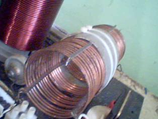
High-voltage diodes (chains) can be purchased ready-made or can be constructed from individual single diodes. The resulting diode chains should have a current rating of not less than 10 amperes at a voltage of 25 kV to 30 kV. It may be necessary to put several diode chains in parallel in order to meet this current rating requirement. Here are examples of these high-voltage diode chains:
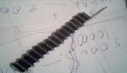
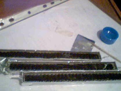
The resonance capacitors (for coils L1, L2) in the primary circuit, need to have a voltage
rating of at least 4 kV, the
capacitance depends on the frequency of the
secondary circuit (28 nF was used by
the author for a resonant frequency of
600 kHz). The
capacitor must be high quality with minimal dielectric
losses and good charge retention.
Usually a composite capacitor bank of low-power capacitors is used. The most appropriate types of Russian capacitors are the K78-2, K78-15, K78-25 or similar types, as these types can easily handle the impulse currents of the discharge.
For the capacitor of the secondary circuit it is better to use any of the
above types of capacitors, but the
composite voltage must be not less than 10 kV. Excellent working Russian capacitors are the KVI-3 type, or
even better, the K15-y2 type.
The secondary coil plus a capacitor form a resonant
circuit. The
capacitor used in the secondary circuit depends on the
desired resonant frequency (the author used a KVI-3 type of 2200 pF and a 10 kV rating).
Here is a photograph of the
capacitor used in the secondary circuit:
The
high-frequency smoothing choke was used, wound in such a way as to get the
minimum value of stray, parasitic capacitance in the inductor windings. The
inductance range of this inductor is
100 - 200 micro-Henry,
and using a partitioned winding helps to keep the coil capacitance
low. The wire diameter
to use is 1.5 to 2.0 mm enamelled
copper wire. Here is a photograph of
one implementation of this choke:
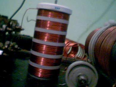
These windings can be made on a PVC pipe
with a diameter from 50 mm to 75mm.
For the storage capacitor bank you can use capacitors with a voltage rating of anything
from 5 kV to 15 kV with total capacity of about 2 microfarads. Suitable Russian oil-filled capacitors, include all types of K41-1, K75-53 and others. This is the circuit
diagram of the device:
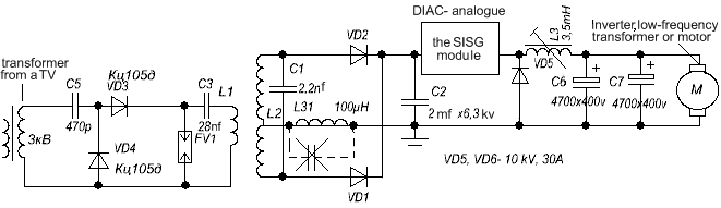
Diodes VD1, VD2 –
high-voltage composites.
Diode VD5 needs to be an
ultrafast type rated at 1200 V, 30-150 Amps.
Choke L3 is any kind with
an open magnetic core, wound with wire of not less than 6 sq. mm., and giving a
1.5 milli-Henry inductance.
The load (an inverter or
a DC motor) requires a low input voltage of 12V to 110 volts (lower voltage -
high power output)
When building and experimenting be sure to take
all Safety Precautions as you will be working with more than 1000 Volts.
Video Links showing this device running an angle-grinder and an electric motor are:
http://www.youtube.com/watch?v=NC3EYDYAXDU #
http://www.youtube.com/watch?v=-sckdMe3HCw#
http://www.youtube.com/watch?v=OaqZ52dGMn4#
The “SISG” module shown in the circuit above
is an attempt to build a solid-state version of a spark gap. In this version of Don Smith’s designs by
‘Dynatron’ he wanted the equivalent of a diac or a dinistor. A dinistor is basically a thyristor or SCR
without the gate. It starts conducting very suddenly if the voltage on it’s
terminals exceeds it’s design value and it stops conducting if the voltage
drops to almost zero or the circuit is disconnected, forcing the current to
become zero. Diacs or dinistors are hard
to find for very high voltages over 5000V, so Dynatron tried to build
equivalent circuits which could be used at high voltage and any one of those
designs is what is indicated by the box marked “SISG”.
Sergei’s Dynatron circuitry
Russian experimenters are well
advanced in their investigations of this type of
circuitry. Here is an attempted
translation from Russian to English, made, I believe by the energetic forum
member “Davi” of
We
begin to draw the schematic diagram

We use a line-scan transformer and point-contact
diodes.
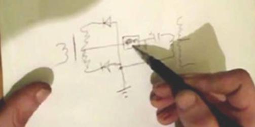
We add in an earth ground, a
capacitor, a discharger, and a second
transformer winding.
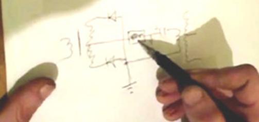
Notice this rectangle.
In the transformer we have an alternating voltage
cycles. If we have a threshold voltage
-control device, such as a discharger, then positive charges will be pumped
from the earth-ground connection, through the diodes. This flow is first, through a one diode, and
then through the other diode. That means
that the secondary winding of the transformer will accumulate a positive
charge. Consequently, you do not need a charged capacitor. Instead of the spark gap which Don Smith
used, you can put a small choke coil of 100-200 millihenrys or a 100 ohm
resistor and either of those work just fine.
The usual spark gap will work perfectly well but it does not have a long
working life. A resistor can be used and
it will work. Vacuum or gas-discharge
tubes work well. The voltage here is around 1000 volts.
While you can eliminate the spark gap, but when you do have one, the pumping of
charges from the ground works better – it turns out to be something like a fork
Avramenko plug. The transformer winding
acts on the ground charge with the aid of the voltages developed in it.
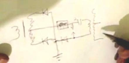
The secondary winding of the resonant transformer,
destroys the dipole, according to Don Smith.
As he explained, the upper plate of the capacitor develops a high
voltage from the charges drawn in through the earth connection. This high voltage is then discharged through
a diode or a spark gap.
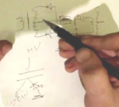
The
same thing happens here.
The ground charge enters the secondary winding, and
due to it’s self-capacitance, accumulates a high voltage on the winding. The diodes used in this location need to be high
quality diodes which have a low capacitance.
For example, Don Smith used diodes which have a capacitance of just 4
pF.
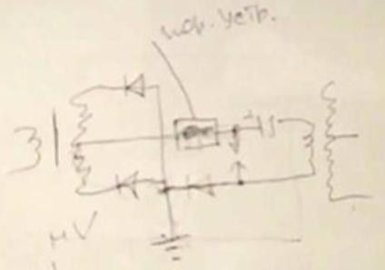
At this point, the pumping scheme will look like this, and I
think that it will not change.
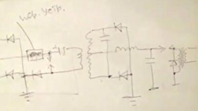
The
second coil is exactly the same as the first coil.
For the time delay we use a choking coil. The capacitor is an electrolytic type and we
use a spark gap to feed an isolation transformer. To
ensure that there will be no feedback of unwanted voltage spikes, we connect a
6 kV 20 to 50 A high-voltage diode in parallel with the primary winding of the
isolation transformer. This can
be arranged by connecting three 1000V diode bridges together like this:
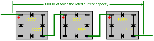
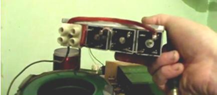
Three
1000V diode bridges can be connected to withstand a voltage of 6 kV.
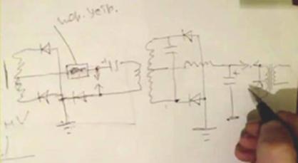
The spark gap is inserted in
the positive wire, the same as the first spark gap . Why is this?
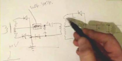
Here we have a separation of
electrons.
We collect electrons both from
the air and from out of the ground. We
push the negatively charged electrons into the ground, and so a positive charge
accumulates in our capacitor.
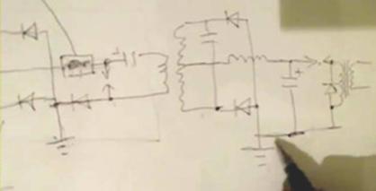
The
ground wire carries the negative charges into the earth (which is an expansion
tank).
If you connect the spark gap between the earth and
the upper end of the transformer which is positively charged, then the primary
winding wire will get warm, and the efficiency falls. When correctly connected the primary winding can be constructed with
wires which are 0.5 -1.0 mm diameter and the wires remain cold.
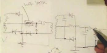
If we have achieved the
splitting of the electron-positron pair, then if you put them in a discharger,
or in a transistor, or whatever, only the radiation remains. However, the really important fact is that
the magnetic component passes through the primary winding of the transformer,
and it induces a strong magnetic field in the secondary winding.
Don Smith said that if you connect
two batteries together and one is say, 30 volts, and the other 10 volts.
The 30-volt battery passing 10-volt,
the electrons in each battery resist each other. It
appears that they do not “like each other” if one can describe it that
way.
The same thing happens in an ordinary
transformer. The current flowing in the
secondary winding resists the flow of current in the primary winding - back
EMF. But the following question is
relevant: at the instant when the negative ion-electrons just start to flow in
the primary winding, the interaction between the primary and secondary windings
is absent. Because of this we get a huge load-carrying capacity in the
secondary winding, practically without changing the inductance of the primary
winding, well, if it is changed then that will be not more than 10% to 20%.
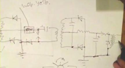
Generally, the minimum load impedance will kill the
inductance causing the frequency to change.
But this does not happen here, because the primary current flow is of
another kind, which is not affected by the current flowing in the secondary
winding. That is, moving a small number
of electrons in the primary can cause a large number of electrons to flow in
the secondary winding. The thicker the
wire of the secondary, the more excited electrons there will be there and so,
the greater the current flow in the secondary.
The mass of the secondary electrons does not depend on the mass of the primary
electrons.
The diameter of the secondary winding is not limited. For example, if you use a 110 mm. tube for
the secondary, then the velocity of the electrons flowing through the winding
will be the same as if it were wound with a wire diameter of just 1 mm or 2
mm. This is because the current flow is
not impeded by the resistance.
The magnetic field of the secondary winding does not interact with the magnetic
field of the primary winding. However,
the primary magnetic field accelerates the electron moving in the secondary
winding, i.e. This produces an
asymmetric transformation.
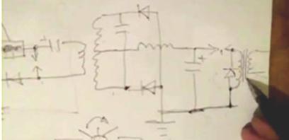
Naturally,
here we need very good insulation.
Roughly speaking, if there
is a small hole in the wire insulation, then the vaporous electrons in the
primary winding will hold the equivalent
vaporous electrons in the secondary
winding, and that will squeeze the heavy electrons in the secondary winding. Consequently, there must be an anti-static screen in the form of a coil, or aluminium
foil that is connected to ground.
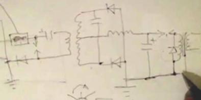
So,
all the positively charged particles should go into the ground
If
you want to ground the output transformer, then do it through a resistor
connected to a ground point which is at least 10 metres away from the first
grounding point in the circuit. The
farther apart the grounding points are, the better, say, 10 to 30 metres
apart. In principle, the length of the
ground between the two ground connections can be considered to be an isolation
capacitor between those two points in the circuit.
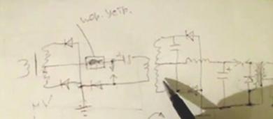
The big question is, of
course, what should be the ratio of the primary winding
turns to the secondary
winding turns - 1:4 ? but here is some good advice:
Accurately measure the total
length of the secondary winding and make the primary winding wire length exactly
one quarter of the wire length of the
secondary winding. The connecting wires are not considered in
this measurement, and it is better to make them thinner. If,
for example, the primary wire has a cross-sectional area of 8 sq. mm, then make
the connecting wires 2.5 sq. mm. in cross sectional area.
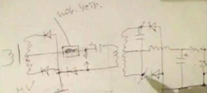
In other words, here are the
terminals of the secondary winding.
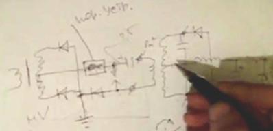
The oscillation amplitude increases massively at the
resonant frequency. Why is that?
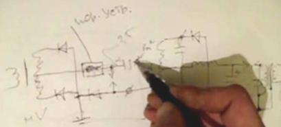
Because
of the change in impedance at the junction between the two wires, the
connection becomes
a
node and this is reflected in the anti-nodes, and the primary waveform remains
a standing wave.
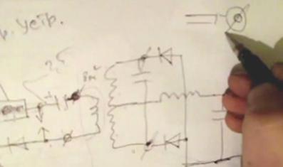
You
will recall that Don Smith used a very thick cable but he reduced it to become
a thin connection at each end. That
thick-to-thin change causes a reflection of the wave. The secondary winding has LC resonance but
the inductor depends on it’s wave resonance length.
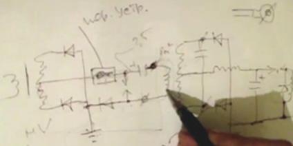
In
fact, what we have here is a Tesla transformer, i.e. voltage, current.
You will recall that even in
the green box of Tariel Kapanadze with it’s thick pipe coil, that thin wires go
from the pipe to the spark gap. Changing
the impedance of the wire at the junction between the two different
cross-sectional areas - That's it! That raises the efficiency, and so the spark gap works better.
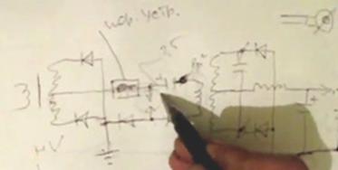
Ideally,
you want to use a vacuum spark gap.
Unfortunately, our spark is
not dispersed in the secondary winding.
The spark might be triggered at anything from 50 kV up to 100 kV. We have a
great ‘Q-factor’ (coil ‘Quality’
factor) in our winding! However,
once the spark has occurred we get a roll-back
of current moving in the reverse direction through the winding, although it is
always less powerful than the forward action.
This reverse pulse also
passes through the spark gap, effectively shunting, the input circuit and so, decreasing the output Q of the circuit. The
circuit’s output voltage is reduced.
The resonant frequency drifts
and so the output power drops. Although this effect can be seen when using
an air gap, it is much better to use either a vacuum spark gap or a spark gap
which is enclosed in a tube filled with hydrogen gas.
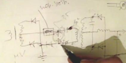
You can put a diode in series with the spark
gap.
If that is done, then the
reverse current will not pass. The
diode must be able to withstand a reverse voltage of 10 to 20 kV. We
ordered a hydrogen diode with power handling capacity of 120 watts. It’s
turn-on time is 0.1 ms, off time is less than 1 ms. We connected the current transformer using 24
ohm resistor. The result was a pure
current transformer on the load, and without any interference. Let's see what we have done on the
discharger. Take a look - the spark gap
was lit up with a blue colour.
On
the oscilloscope, we see dampened oscillations.
There must be only one
oscillation, and the remaining excess. The 5
extra vibrations short-circuit the secondary winding, and prevent it from
operating normally.

Ideally,
this should be simple.
Clicking
the inductor - capacitor recharges, but the current does not go back. (it stops
at zero)
Picture voltage "U".
Picture current "I".
That is how such a process should be,
but otherwise - buffeting vibration. (need a hydrogen diode)

Isolation
transformer.
The isolation transformer is
made up of rings. The
primary winding is 2 bifilar layers wound in one direction. The
secondary winding is with wire which has 10 sq. mm. cross sectional area, but
today we will rewind it. The screen is made of foil - ordinary Scotch
tape. But the screening must not
form a complete turn as it must not be a
closed-loop. Here, aluminium Scotch tape is used. Now short-circuit the
secondary winding, and enable the device.
We check with a screwdriver, and there is practically
no output. If you add an anti-static
barrier, i.e. gasket between the primary and shield. It should be made from a good insulator, such
as PTFE. It is possible to use
cellophane which, being like acrylic is also a very good insulator. I shorted outputs, so as not to clatter. If you remove the jumper, the coil is
bursting with no load like this. (We
hear a crash, and after 3 seconds it stops) Sergey: We'll see what it was. (Blue spark coil pierced).
That's it! The experiment’s completed. Blown diode bridge - Accident. Accidentally shorted to ground. Well, that's all. It is desirable, of course, have a good
ground connection. The
threshold-limiting device is a choke.

What
can I say?
In principle, you can use the CISC module instead of a
spark gap. In this circuit, the very
sharp rise time of the driving waveform pulse fronts is not necessary, because
the inductance is large.
If the transformer has an
iron core, then the rate of charging of the capacitor will be very fast, at, for example, 50 Hz. At that low rate, you can omit the
discharger. In Don Smith’s design where a neon tube driver
is used, a diode and even a diac can be used instead of a spark gap. It will
even work with a direct connection.
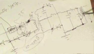
Then the impulses are often, but with smaller
amplitude. Naturally, the better, when
we divide the frequency, i.e. for two of the primary pulse charges the
capacitor of the secondary.
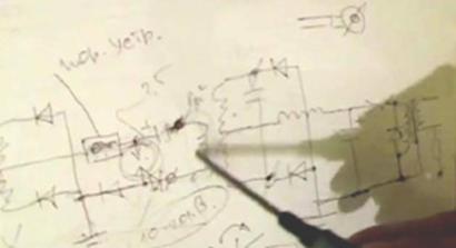
Then the amount of energy in the pulses is summed.
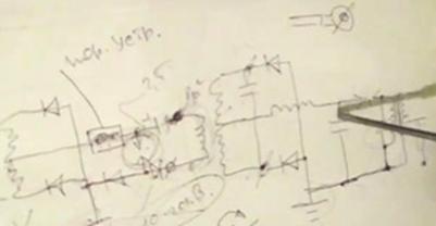
Here they are superimposed
on one another, in a linear fashion.
C = Q/U end U = Q/C
The capacitance is a
constant. If we increase the number of
charging pulses per second, then because the secondary coil at resonance
increases the amplitude of the pulses, we get increased power. At 5 times more power, because there are 5
times the number of charging pulses passed to the capacitor, we get a squaring of the voltage-energy. That
is an energy increase of 25 times.
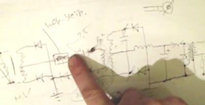
Raising the spark frequency
by, say a factor of 10, will give an energy gain of a factor of 100.
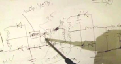
Well, I'm telling you,
place a spark gap here in order to – INTERRUPT. Otherwise,
the inductor will not be able to speed up and pass
more pulses into the capacitor.
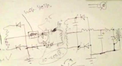
Gentlemen! Make it and test it.
The Rosemary Ainslie
Energy-Collection System
For many years now, people
studying science-related subjects in universities around the world, have been
told things which are at best, out of date, and at worst, deliberately
incorrect. For example, a common starting
point for analysis is to assume "a closed system" although it is
perfectly clear that there is no such thing on the planet.
With few exceptions, calculations
are generally based on the assumption that energy does not flow into a system
or a device from the outside. The
influence of sunlight is one of the few external inputs recognised, and it's
effect on solar panels, producing rainfall, causing winds, etc. are admitted
because these things are so obvious to the average person that there is no
denying them.
These same people fight tooth and
nail to persuade people that "space" is empty and that there is
nothing in it. This is, of course,
ridiculous, since light passes through space, as do radio waves, X-rays, cosmic
particles, and other things. It is
certainly a weird notion that distant objects can affect each other if there is
absolutely nothing in between them. It
would be a neat trick to explain the effect of gravity if there is absolutely
nothing in the gap between them.
The matter has long since left the
realm of common sense as the British scientist Harold Aspden has demonstrated
with laboratory measurements, the presence of an "unknown" field
which acts like an incompressible gas.
What his work has demonstrated is now known as "the Aspden
Effect" and the experimental results are as follows:
Harold was running tests not related
to this subject. He started an electric
motor which had a rotor mass of 800 grams and recorded the fact that it took an
energy input of 300 joules to bring it up to its running speed of 3,250 revolutions
per minute when it was driving no load.
The rotor having a mass of 800 grams
and spinning at that speed, its kinetic energy together with that of the drive
motor is no more than 15 joules, contrasting with the excessive energy of 300
joules needed to get it rotating at that speed.
If the motor is left running for five minutes or more, and then switched
off, it comes to rest after a few seconds.
But, the motor can then be started again (in the same or opposite
direction) and brought up to speed with only 30 joules provided that the
time lapse between stopping and restarting is no more than a minute or so. If there is a delay of several minutes, then
an energy input of 300 joules is needed to get the rotor spinning again.
This is not a transient heating
phenomenon. At all times the bearing housings feel cool and any heating in the
drive motor would imply an increase of resistance and a build-up of power to a
higher steady state condition. The
experimental evidence is that there is something unseen, which is put into
motion by the machine rotor. That
“something” has an effective mass density 20 times that of the rotor, but it is
something that can move independently and take several minutes to decay, while
the motor comes to rest in a few seconds.
Two machines of different rotor size
and composition reveal the phenomenon and tests indicate variations with time
of day and compass orientation of the spin axis. One machine, the one
incorporating weaker magnets, showed evidence of gaining strength magnetically
during the tests which were repeated over a period of several days. This clearly shows that there is an unseen
medium which interacts with everyday objects and actions.
Bob Boyce of the
There is extremely strong evidence
that this is so, because five independent experimenters have demonstrated this
inward energy flow, using Bob's toroidal transformer to charge batteries. One man who lives in
The little girl does not know this
and drives around happily each day. The
battery in her car has been recharged this way more than thirty times. This would appear to be direct evidence of
energy flowing into the charging system from the outside. Achieving this is not an easy thing to do,
quite apart from the fact that most sensible people are very reluctant to have
the output of any system fed back to the input of that same system as that is
positive feedback which easily leads to power runaway. The preference is to have one twelve volt
battery charge a separate forty-eight volt battery bank because doing that
avoids any possibility of excessive feedback.
As with most systems, the practical
details are a key feature. In this case,
the toroid is a MicroMetals 6.5 inch iron-dust toroid which is precision
hand-wound with three separate windings of solid, silver-plated copper wire
with a teflon covering. These three
windings are pulsed in turn with a complex waveform signal, creating a
high-speed rotating magnetic field which has no moving parts. A rotating magnetic field like that has long
been known to produce excess power with a RotoVerter system constructed from
two off-the-shelf 3-pahse motors, having a power output well in excess of the
power input needed to make it run.
This inflow of outside power is a
feature of Rosemary Ainslie's heating system.
Rosemary has designed and laboratory-tested a heating system which can
have substantially more output power then the input power needed to run
it. She achieves this by pulsing a
heating element in an unusual way using this circuit:

Most circuits which draw energy in
from the local environment, generally need to be tuned to achieve resonant
operation. It is also found that a
waveform rich in harmonics is needed to produce the best results. For example, Ronald Classen recently produced
an analysis of the operation of Bob Boyce's electrolyser toroid pulsing. Bob's circuit generates three separate
waveforms, one at about 42.8 kHz, and two harmonics, one at around 21.4 kHz and
the other at about 10.7 kHz. He
examined the operation with the two harmonics slaved exactly to the master
frequency and then with the two harmonics free-running and not quite synchronised,
so that a random pattern of harmonic pulses were generated. Surprisingly, he found that the random
arrangement gave much higher gains than the "precision" circuit.
The same sort of situation is found
here in the Ainslie circuit as very precise adjustment of the "Gate"
preset resistor "R1" has a major effect on the circuit performance
while the other two, R4 and R7, are used to adjust the frequency of the pulses
and the ratio of "On" time to "Off" time. Like almost every other circuit which produces
a greater power output than the input power required to make it operate, very
careful adjustment is needed. The
characteristics of the "Load" heating element "R3" are also
very important. With some
configurations, there is no excess power generated, while with others there is
a very marked increase in power and the prototype apparatus produced power
outputs in excess of four times the input power.
A quick glance at the circuit
diagram makes it appear that there is no significant connection between the
NE555 timer chip and the IRFPG50 FET transistor. This is not the case as the arrangement as
shown generates transients which modify the oscillation of the NE555 chip. This is presumably due to the nature of the
current draw by the gate of the FET or through induced currents caused by the
pulsing of the inductive load heater coil "R3". We tend to think of FET transistors as having
next to no current flowing into the gate, but the IRFPG50 FET can draw up to a
massive 6 amps for the Gate to Source current flow. The NE555N chip supplying that gate current
(with no current-limiting resistor between the two devices) can supply a
maximum of only 200 mA (or possibly 300 mA at a push) which is only 5% of the
possible current draw by the FET. The
circuit of the NE555N chip is:
From this it appears that the direct
coupling of the output could allow some modification of the chip timing and
waveform if the output current draw is well above the design value, the internal
resistors preventing destruction of the chip and reducing the effect so that it
just modifies the functioning of the chip.
This is also suggested by the fact
that the adjustment of the "Grid" variable resistor, which controls
the NE555N current draw, is the most critical adjustment of the circuit. Supporting that idea is the fact that the
required chip operation does not take place if the "Grid" resistor
setting is too high or too low.
Presumably, the setting has to be an exact amount so that the NE555N
chip operation is altered to make it generate waveforms not envisaged by the
chip designers. The physical separation
of the "Load" resistor and the circuit board may also be important as
there is almost certainly a magnetic feedback element as well.
I would love to tell you that the
circuit operates in the way that the circuit diagram would suggest, with the
timing and Mark-Space values controlled as expected by the 555 chip
designers. However, that is definitely
not the case. If the 24V battery is
disconnected, then the NE555 chip section of the circuit performs exactly as
expected. If the "R1" GATE resistor is at the correct setting
and the 24V battery is then connected, the result is that the normal running of
the NE555 chip is overridden and the circuit immediately switches into a
completely different type of operation.
The Mark-Space ratio is forced into an approximately 55% setting and the
pulsing rate is bounced to over 500 kHz (well beyond the capability of the
NE555 chip, as many actual chips can't even reach 45 kHz in practice) with this
waveform:
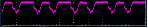
which you will note has repeating
pairs of pulses, neither of which is a square wave. The overall circuit is clearly not operating
as an NE555 chip circuit any longer but is oscillating in an unexpected
way. This high radio-frequency pulsing
produces electromagnetic waves which radiate out from the load resistor, an
effect which is seen on a nearby television set. This is not really surprising, as the circuit
should really be presented like this:
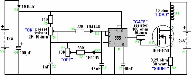
This is because the 10 ohm
"resistor R3" is actually a coil of wire. The specification for this component shows
that it has a length of 150 mm (6"), a diameter of 32 mm (1.25") and
is an air-core coil, wound with 48 turns of resistance wire with a 1 mm gap
between each turn. The lack of a core,
allows the coil to oscillate at this high frequency, and any coil driven at
that frequency radiates radio waves.
It is almost certain that these
electromagnetic waves are inducing voltages in the wiring surrounding the NE555
chip circuit, causing it to run wildly outside its design. The wire-wound adjustment resistors are
little coils which have the potential for picking up transmitted waves. This pickup mechanism is strongly supported
by the fact that only an NE555N chip will operate in this way and three other
makes of 555 chip which were tested, failed to produce this runaway
action. The higher runaway frequency is
important for achieving power gain. Don
Smith states that the extra power being drawn into a circuit is proportional to
the square of the pulse frequency. If
this is correct, then moving the pulse rate up to over 500,000 per second will
have a major energy effect and explain why tuning the circuit into this
high-speed mode is important.
The practical method of tuning the
circuit into its self-oscillating non-symmetrical, power-gaining mode is by
monitoring the voltage of the "V1" 24V battery. When the circuit is out of tune, the battery
voltage gets pulled down quite noticeably.
When the circuit is tuned correctly, there is a slight increase in the
battery voltage. If the circuit has been
built as described, using an NE555N timer chip and a high inductance load
"resistor" coil, then tuning the circuit is performed as
follows: Connect a digital voltmeter
across the 24-volt power supply and note the exact reading. Set the "ON" preset resistor to its
minimum value of zero ohms. Set the
"OFF" preset resistor to its maximum value of 10K ohms. These resistors are generally left at these
settings throughout.
The "GATE" resistor is now
adjusted very carefully, watching the voltmeter reading. As the circuit comes to its best possible
tuning, the battery voltage will rise. Pick
the resistor setting which gives the highest battery reading. The rise in battery voltage is caused by the
inflow of external energy. Some of this
flows through the "LOAD" causing heating effects which can be 17
times greater than would normally be expected.
Part of the inflowing energy flows back into the power supply, and that
flow lowers the current draw from the 24V battery, which in turn, allows it to
show a higher voltage reading. This
mechanism is exactly the same as described by Tom Bearden when explaining the
operation of John Bedini's battery-charging pulse circuits - part into the load
and part back into the power supply.
Although it is not mentioned in the
Parts List, it is very important to mount the FET transistor on a heat sink as
the current flowing through it causes it to heat up. Also important is to use a mica gasket
between the FET and the heat sink. A
mica gasket is a thin layer of mica which electrically insulates the FET from
the heat sink while still acting as an extremely good conductor of the FET heat
to the heat sink. This is necessary
because the "Drain" pin of the FET is connected electrically to the
metal mounting strip of the FET and if the FET is not insulated from the heat
sink, then the heat sink acts as a radio aerial and radiates an embarassingly
large level of radio waves. The heat
sink can be a simple sheet of aluminium, or it can be a commercial finned
design of which there are many from which to choose. A suggested physical layout for this circuit
is given towards the end of this document, and can be used if you are inclined
so to do.
This is a circuit which cries out
for replication and investigation by both experienced and inexperienced
experimenters. There are no expensive
components in the circuit and the circuitry could hardly be any more simple
than it is. If this circuit can be
scaled up to operate as a household heater it would mean that electrical
heating costs could be reduced to a tiny fraction of what they are at the
present time. That sort of cost
reduction would make a major difference to a very large number of people, which
makes this circuit very interesting indeed.
A website which has a considerable
amount of interesting information on this design and the history surrounding it
can be found at: http://www.free-energy.ws/rosemary-ainslie.html
The operating methods which are used
in this style of circuitry are describe in considerable detail in a patent
application (WO 99/38247) has been filed for this system. Reading those descriptions can be helpful, so
here is a digest of part of that patent:
Patent: WO 99/38247 Date: 22nd January 1999 Inventor: Rosemary A. Ainslie
HARNESSING A BACK EMF
ABSTRACT
A method of achieving high
efficiency of energy usage which includes passing current through an inductor,
causing the current to be repeatedly interrupted, thereby generating a back EMF
in the inductor and thereafter, harnessing the back EMF so generated , to
supply energy to an energy-receiving or processing device. The frequency of interruptions should be 40
Hz or more and is achievable by rectifying the current. The invention extends to apparatus for
harnessing such back EMF and energy generating means comprising an inductor and
a current interruptor connected to an energy-receiving device.
FIELD OF THE INVENTION
The invention relates to a method of
harnessing back EMF for use in powering a load or replenishing a depletable
energy source and extends to apparatus used in performing the method.
BACKGROUND OF THE INVENTION
Conventional switching circuits are
well known in electrical energy conversion technology, and switch mode systems
have been employed to enhance energy utilisation efficiencies. The concept of absorbing electrical energy
released by the collapse of auto-electronic emissions from a discharge tube is
disclosed in US 5,449,989. This document
discloses a circuit which includes an output port connected to a current sink
which is able to absorb at least a substantial portion of such emissions. The current sink may be an electric motor or
a secondary battery.
The concept of applying a back EMF
in electrical circuitry is also known.
For example, in US 5,521,476 there is disclosed a control circuit for a
disc drive motor, in which back EMF blocking circuitry is employed to prevent
dissipation of a back EMF through a power supply. By contrast, publication WO 9,613,892
discloses the use of a back EMF to trigger a response in a control system for a
mechanical system, so that driving pulses are generated to accomplish a desired
displacement motion.
In the present invention, to achieve
high energy efficiencies, greater than unity in relation to a conventional test
circuit, a back EMF which is generated in an inductor, is harnessed so as to
return energy associated with the EMF, to a depletable energy source which is
supplying such a circuit, or to a load included in the same primary circuit as
the energy source. It is envisaged that
a wide range of electrical supply sources will derive benefit from the
invention disclosed below.
A first aspect of the invention is a
method of harnessing back EMF in an electrical circuit in order to increase the
efficiency of energy usage to 90% or more, (compared to a Resistor-Temperature
v Wattage calibration circuit). This is
done by arranging the circuit so that it contains an inductor and an
energy-receiving device configured so that the current flowing through the
inductor generates a back EMF whose energy is used to provide both additional
energy to the circuit itself, and the back EMF energy to the energy-receiving
device.
In a preferred form of the method,
the back EMF is generated by interrupting the current flow through the
inductor, ideally, interrupting and restoring the current flow repeatedly and
rectifying the current. The rate of
interruptions should be at least 40 times per second and preferably 50 or more
times per second. The duty cycle of the
interruption should be at least 50% and ideally be 75%. That is, the current flow through the
inductor is "On" for 50% to 95% of the time and "Off" for
50% to 5% of the time.
In a further preferred form of the
invention, a back EMF is generated which is large enough to cause the
comparative energy efficiency to be at least unity. This can be achieved by setting and
controlling a suitable value for a variable selected from one or more of:
The frequency of interruptions from the wave
rectifier;
The duty cycle;
The thickness of the wiring in the circuit;
The efficiency of the inductor core,
the value being set in accordance
with the operational requirements of the desired application.
In another preferred form of the
invention, the energy-receiving device is either an energy-requiring load,
and/or an energy storage device, ideally a replenishable source of either DC or
AC electrical energy. Ideally, the
method also includes providing at least one inductive load associated with each
receiving device. The inductor may be a
transformer or other suitable inductive device.
A second aspect of the invention is
a method of restoring electrical energy to a source, which is done by providing
a closed circuit containing a source of electrical energy which passes current
through the inductor, creating an extruded magnetic field around the inductor,
which field is then collapsed, creating a back EMF which is then fed to the
source with an energy usage efficiency factor of 1 or more when compared to a
Resistor Temperature Versus Wattage Calibration Circuit.
This feedback of energy can be to an
energy-requiring load or to an energy storage device.
In a further preferred form of the
invention, the bias-changing mechanism is a wave rectifier and the method of
use is to make the wave rectifier output interrupt the electric current.
Ideally, the inductor used should
have a solid core which is capable of inducing a magnetic moment associated
with a collapsing magnetic field.
The method used in this invention
includes selecting a value for:
The frequency of interruptions from the wave
rectifier;
The duty cycle;
The thickness of the wiring in the circuit;
The efficiency of the inductor core,
so that the magnitude of the back EMF
generated when the magnetic field collapses, is in a predetermined range which
suits the requirements of the energy-receiving device and its intended use.
In one preferred form of the
invention, the inductor is a transformer with a primary winding large enough to
create sufficient voltage from the back EMF, to feed power back into the
circuit. If the current feeding the
inductor is AC, then the current interruptor can be a diode or a triac.
A further aspect of the invention is
an apparatus comprising an inductor having a core suitable for the generation
of back EMF from collapsing magnetic fields, and an electrical circuit
containing that inductor, a replenishable energy source, and energy-receiving
device and means for changing orbital bias of a magnetic field set up in use
and associated with the inductor, both it and the source with variable
frequency and variable Mark-Space ratio, being configured to operate the
inductor, and arranged so that the magnetic field of the inductor is made to
collapse and be restored repeatedly,
thereby generating electrical energy, the circuit being capable of conducting
the energy and providing it to the energy-receiving device.
A BRIEF DESCRIPTION OF THE DRAWINGS
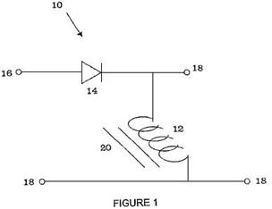
Fig.1 illustrates schematically, a circuit to which the invention
may be applied.
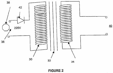
Fig2. illustrates an electrical generator
which may be used with this invention.
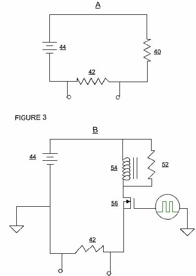
Fig.3A illustrates a control circuit which
is described in Example 1 below, and Fig.3B illustrates a test
circuit, the performance of which is compared with the circuit shown in Fig.3A.
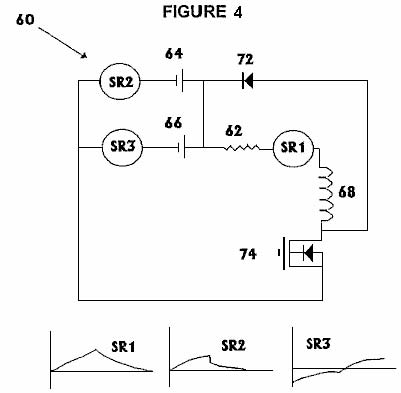
Fig.4 illustrates the test circuit
described in Example 2 below.

Fig.5 illustrates the circuit referred to
in Example 3 below.
DETAILED DESCRIPTION OF THE INVENTION
By connecting an inductor in a
load-bearing circuit and causing back EMF to be established in the inductor,
there may be created a voltage of sufficient magnitude to restore energy to the
circuit's source of power and so reduce its rate of depletion. It is not suggested that the load would
consume less energy, but that additional energy from the back EMF can be
supplied to either the load or the power source supplying that load.
The circuit can be supplied with either
DC or AC power and while the inductor may be any suitable inductor, the use of
a transformer is preferred. An
alternative is a winding or a choke, preferably containing a core capable of
inducing a magnetic moment associated with a collapsing magnetic field -
typically an iron core, but it could be any suitable liquid or gaseous medium
or combination with or without additional solids.
To generate back EMF, the current
flowing through the inductor needs to be interrupted repeatedly which can be
done by any suitable means. A preferred
method is the use of a variable-duty cycle chopper. If the current is AC, then the interruption
can be cause by using a wave rectifier such as a diode or a triac. If the current is DC, then the current
interruption is achieved by the use of an oscillator, MOSFET or an equivalent
means whereby a fluctuating magnetic field in the inductor can be created.
The method of recycling energy which
is the substance of this invention has the following steps:
(1) Setting up a
circuit containing an inductor which has an extruded magnetic field and which
is arranged in such a way as to allow electrical energy to be passed both to
and from the inductor, and
(2) Changing the orbital bias of the
magnetic field around the inductor, causing the collapse of the magnetic field
and the creation of the back EMF current.
These two steps are repeated in
rapid succession and when the current flowing through the inductor is interrupted,
an alternative circuit is provided in order to direct the back EMF current to
the desired destination. Preferred
inductor core materials are iron and other ferrous materials.
The circuit does not need to be
complicated but it needs to be able to either interrupt or reverse the current
through the inductor as already described.
The invention will now be described in greater detail by referring to
the diagrams:
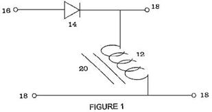
In Fig.1, the wave rectifying
diode 14 is placed in series with a primary inductor 12, and acts
as an interruptor of the electrical current supplied to the circuit. If a sine wave or square wave waveform is
applied to the circuit through points 16 and 18, a pulsing DC
waveform is created in the winding of inductor 12. The interruption of each waveform cycle in
the inductor winding 12, induces a fluctuating magnetic field in the
iron core 20 inside the inductor.
It is thought that the back EMF
causes a reverse waveform in the inductor winding 12 which is a full
sine wave in the case of an alternating current powered circuit, or a full
square wave if the circuit is powered by DC pulses. The inductor 12, may be connected with
a load (not shown) in series or in parallel at any of the points marked 18.
Depending on the frequency of the
interruptions, the duty cycle, the thickness of the wiring and the efficiency
of the core, the voltage across the inductor 12 may be conducted through
a closed circuit to be used in powering the load or returned to the power
source. It is desirable, though not
essential, that the frequency of interruptions should be not less than 40 Hz
although 500 Hz or higher is more appropriate for some applications.
An example of a suitable closed
circuit employing such a system is a battery powering a lamp. A transformer may be connected in series with
the lamp along with a current chopper which has a variable duty cycle. The output from the transformer can be routed
through a diode, a high value resistor and a capacitor all in series. Here, when the chopper service is on, the
current flows through the load and transformer.
Repeated opening and closing of the current-chopper system causes the
generation of electric current in the transformer secondary and that current is
passed back to the battery, exceeding the current draw.

Fig.2 shows another variation of the
circuit where a primary winding 30, having for example, 220 turns around
a cylindrical core 32, made of a ferrous metal such as iron or an iron
alloy, is associated with a secondary winding 34 of about the same
number of turns. The secondary winding
is wound around the core adjacent to, or on top of the primary winding 30,
producing a magnetic coupling between the windings, enhanced by the core 32. The circuit input 36 is connected to
an AC source 38, typically a 220V 50Hz mains supply. The circuit output is taken from the
secondary winding 40. A diode 42
is connected in series with the primary winding 30, causing the
full-wave AC input to become a pulsating input to that primary winding.
On each positive-going half cycle,
the primary winding induces a corresponding current in the secondary winding 34. However, when, due to the blocking effect of
diode 42, the magnetic field resulting from the current in the primary
winding 30 collapses, the resulting back EMF in the primary winding
induces a corresponding negative-going waveform in the secondary winding 34. Hence the output 40 from the secondary
winding is a full-wave AC waveform.
Although this description is for a
circuit with one inductor, it is clear that additional inductors could be used
to achieve even greater enhancements in system performance. For example, two or more primary windings
could be wired in parallel where just one is shown in Fig.2 above, each
providing a separate, independent full-wave AC output. Alternatively, more than one secondary
winding can be placed on the transformer core, utilising the magnetic coupling
of the core.
Example 1: Two tests were conducted on two wire-wound, 10-watt
resistors manufactured by Philips. The
resistors have identical surface areas.
The object of the test was to compare the rate of current draw of a
standard "Resistor temperature Versus Wattage Calibration Circuit"
(the "control") indicated in Fig.3A:
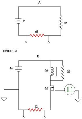
to a test using a switching device
and an inductor as indicated in Fig.3B.
The same battery was used in both tests.
The control test shown in Fig.3A, had a thermocoupled 68 ohm
resistor 40, and a sensing resistor 42, placed in series with the
battery terminals 44. All
measurements were made after the temperature of resistor 42 had reached
its maximum value of 95OC.
The current was measured as being 196 mA and as the battery voltage was 12.28
volts that represents a power level of 2.406 watts.
The test circuit shown in Fig.3B,
had a MOSFET switching circuit transistor 56 driven by a square wave
signal (shown in green) whose Mark/Space ratio was adjusted until the load
resistor 42 reached its highest value of 93OC and all quoted measurements were made after that
time. The pulsing signal was running at
5kHz with an "On" time of 22.87% and an "Off" time of
77.13% of the time. The current flow was
measured as 171.8 mA which represents a power input of 2.109 watts. The room temperature remained the same during
the entire test period.
Allowing for a 5% error in the
measurements, this result shows an energy output which is 8.6% greater than the
power input, or COP=1.086.
Example 2: The following tests were conducted to prove that subject to
specific circuit configurations, an inductor is able to enhance energy
efficiency to levels beyond the standard capabilities of an electrical power
supply source. The tests also indicate
that if a resistor is placed in series with a power supply and an inductor as
shown in the Test Circuit, then the correct wattage analysis of that power may
be calculated as the energy source voltage multiplied by the amperage (V x I)
and that I2R no longer holds as a base
calculation of the wattage and power generated in this particular system.
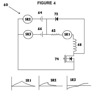
With reference to Fig.4, the
Test Circuit 60 comprised a 47 ohm, 10 watt, Philips wire-wound resistor
62, placed in series with two 6-volt batteries, 64, and 66
connected in parallel. A inductor 68,
was placed in series with load resistor 62. A positively-biased diode 72, was
placed in parallel with the inductor 68 and above an n-channel MOSFET
transistor switching device, 74.
This wire was then taken back to the positive terminal of the
batteries. The battery voltage was
measured at 6.12 volts.
The duty cycle was adjusted to a
50:50 Mark-Space ratio, giving equal times for the On condition and the Off
condition. The load resistor reached a
temperature of 30OC and the ambient room temperature
was 22OC.
The waveforms for the three sensing resistors SR1, SR2 and
SR3 are shown in Fig.4 below the circuit diagram.
The voltage waveform across the SR1
sensing resistor in series with the load resistor 62, is roughly
triangular but followed an exponential rise and fall during the On and Off
periods of each cycle. The voltage did
not fall below zero. The peak positive
voltage was measured as 0.006 volts which corresponds to approximately 0.169
watts which is less than would be expected from the temperature of the load
resistor. It would be expected that
0.375 watts would be required to produce the measured 30OC of the load resistor 62.
The voltage waveform across the SR2
sensing resistor placed in series with battery 1, marked 64, was roughly
triangular in form with some exponential curvature as shown. The average current draw from the battery was
measured and calculated to be 0.025 amps, which is a power draw of 0.153
watts..
.
The voltage waveform across the SR3
sensing resistor placed in series with battery 2, marked 66, showed a
waveform with equivalent amounts above and below the zero voltage level. The On voltage peak was 0.0055 volts and the
Off voltage peak was -0.0055 volts (i.e. below zero volts). No power was being drawn from this battery
and in fact, the shape of the two sections of the waveform indicate that there
was actually a slight degree of charging on this battery although this was
ignored as being too small to be significant.
The inescapable conclusion from
these tests is that to achieve identical heating of the load resistor, the
standard circuitry required 0.0612 amps while the test circuit required only
0.025 amps. This means that the pulsing
circuit is more than 100% more efficient than the conventional circuit. These measurements represent a Coefficient Of
Performance of 2.45 as the output power is 2.45 times the input power.
These two examples shown here do not
necessarily represent optimised values and further gains may be attained by
using two or more inductors, two or more energy sources or energy storage and
its switching circuitry, and other measures.
Example 3: A further set of tests was conducted to investigate
the relationship between power supplied by the battery marked as 82 and
power dissipated by a resistor R1
in the circuit of Fig.5.
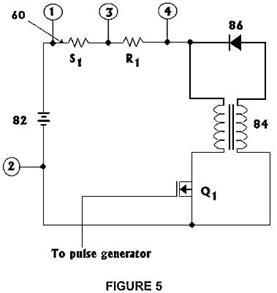
This is to test the efficiency of
the energy conversion as the duty cycle of the FET switch Q1 is adjusted.
This circuit includes an inductor 84, which has equal primary and
secondary windings and a 350 VA rated core.
The circuit also contains a positively-biased diode 86 and other
components mentioned below. The tests
were conducted with "On" times of 90%, 80%, 70%, 60% and 50% and the
results are shown in this table:
|
Duty Cycle |
V1-3 Average |
Average Current |
V1-2 DC |
Power |
V1-3 rms |
RMS Current |
V3-4 rms |
Load Power |
Pload / Pbatt |
|
% |
mV |
A |
V |
W |
mV |
A |
V |
W |
ratio |
|
90 |
69.5 |
1.390 |
12.57 |
17.46 |
102.5 |
2.05 |
10.02 |
20.54 |
1.176 |
|
80 |
38.2 |
0.764 |
12.64 |
9.657 |
73.1 |
1.462 |
7.58 |
11.08 |
1.148 |
|
70 |
20.9 |
0.418 |
12.69 |
5.304 |
51.1 |
1.022 |
5.36 |
5.478 |
1.033 |
|
60 |
7.9 |
0.158 |
12.73 |
2.011 |
34.1 |
0.682 |
3.19 |
2.176 |
1.082 |
|
50 |
1.2 |
0.024 |
12.76 |
0.306 |
15.9 |
0.318 |
0.94 |
0.299 |
0.976 |
**************************
The important thing to note from
these figures is the way that the ratio of the output power to the input power
(which is the Coefficient Of Performance or "COP"), shown in the
final column, varies with the Mark-Space ratio shown in the first column. For all On time ratios over 60% in this very
simple circuit, the COP is greater than 1 which conventional science swears is
"impossible" in spite of it being demonstrated over and over again by
different people and different styles of apparatus.
Rosemary Ainslie's techniques shown
here where the back-EMF pulses are harnessed and used to perform useful
functions, achieve COP values from 4 to 17 in tests performed to date.
John Bedini's captured back-EMF
battery-charging circuits have been replicated with high-voltage battery banks
being charged by one 12V battery and yielding COP=11 results.
The pulse motor design of Robert
Adams which utilises the back-EMF pulses and other techniques, reaches COP figures
of 8 or higher, depending on the quality of the build and the accuracy of the
adjustments.
Thane C. Heins demonstrates on video
http://www.youtube.com/watch?v=RbRPCt1-WwQ&feature=channel a very simple transformer arrangement which
produces COP=3.77 a result which you can easily check out for yourself.
Rosemary's neat technique which
produces this energy gain has every appearance of being a more easily adjusted
method of producing the gains of the Tesla Switch which has to have a
substantial inductive load in order to get its COP>1 performance and which
is very tricky to adjust.
It should be stressed at this point
that it is physically impossible to draw more energy out of a circuit than the
energy flowing into that circuit. Energy
can't be destroyed or created and you can't have more than 100% of anything,
anywhere, any time. But Rosemary Ainslie
and others have demonstrated very clearly that carefully designed and operated
circuits definitely put out more energy than the user puts into the
circuit. I do not know of any way to
prove where that extra energy comes from, but it definitely comes from
somewhere, flowing into the circuit from outside. However, let's not concern ourselves with
trying to discover the source of this extra power and instead, just learn how
to capture and use it for our own benefit.
So, let's recap on how Rosemary's circuitry is set up and used. The initial basic circuit which gives an energy gain is:
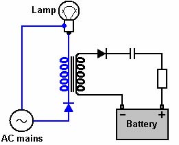
Here, a mains-powered light bulb has
two components connected in its normal circuit.
The first component is a diode "D" and the second a
transformer "T":
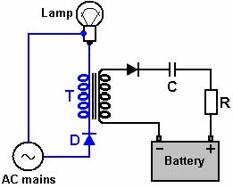
The diode has a very low resistance
to current flow in one direction and a very high resistance to current flow in
the other direction. We tend not to
think about it, but the ordinary mains current flowing through a light bulb
switches its direction of flow dozens of times per second - actually, sixty
times per second in the
If we put a diode in the circuit as
shown in the diagram above, it gets in the way of every second surge of current
through the bulb. This causes the
current flow to be in only one direction and there are fifty or sixty gaps per
second in the flow of current through the bulb.
This pulsing current flow passes through the left hand transformer
winding (shown in blue in the diagram), called the "primary" winding,
and it generates a voltage and current flow in the other winding of the
transformer (shown in black in the diagram and called the "secondary"
winding).
The two lines drawn between the two
windings indicate that the transformer has some kind of magnetic core. Having a core in a transformer can be a very
mixed blessing. It will work very well
if there is no core material - generally called an "air-core"
transformer. Energy gains in a circuit
like this, increase with increased voltage and even more so with increased rate
of pulsing (called the signal "frequency"). An air-core coil or transformer will operate
at very high frequencies, limited mainly by the wire diameter. Most powerful transformers are usually
supplied with an iron core as that improves their magnetic coupling at the very
low pulse rates used with mains power.
That iron core has very limited frequency performance as it is limited
by how fast the iron can alter its direction of magnetisation. It is unlikely that you would get good
performance even at the low frequency of one thousand pulses per second
("1 kHz"). As each of these
pulses feeds a little packet of extra energy into the circuit, obviously, you
would like as many as possible per second, so that the energy inflow is very
great. You will notice in Rosemary's
patent, that she mentions raising the pulse rate to five hundred per second to
increase the power gain.
However, that does not matter here as we are using a mains electrical supply which is just creeping along at well under one hundred pulses per second in order to explain the technique in a simple form. Anyway, the voltage generated in the secondary winding of the transformer is a full-wave voltage waveform just like the original mains waveform with no gaps in it. This energy in the secondary winding could be used for a wide range of different purposes. The one shown here is the charging of a battery or a bank of batteries arranged to work at almost any voltage. Contrary to popular belief, the voltage used to charge a battery is not particularly important provided it is high enough, but what is very important is the current flow into the battery, and that needs to be controlled carefully. Ed Gray demonstrated that charging with a high voltage was a perfectly good method and he used a capacitor to control the current flow into the battery. Eventually, he gave up doing that and used an ordinary car alternator to charge the battery as it was difficult to get the capacitor value just right to achieve the desired current.
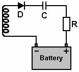
Rosemary uses the same technique but
adds in a resistor "R" to make sure that the charging current never
becomes excessive. The diode
"D" converts the alternating voltage in the transformer winding to
positive pulses, that is, pulses where the voltage rises above zero volts and
never falls below zero volts. This is
the sort of voltage which we need for feeding to the positive terminal of a
battery.
In passing, while the capacitor "C" does act as a current-limiting device, it may also act as a conversion device as extra energy flowing into the circuit from outside can be of a somewhat different type to the electrical current drawn from the mains, and a capacitor is a well-proven method of converting the incoming energy into the more familiar conventional form.
So, looking at the circuit again,
the mains is converted to a pulsing 50% Mark-Space ratio current flow through
the primary winding of the transformer "T". When that flow cuts off suddenly, there is an
inflow of energy into the winding from outside the circuit, forming what is
called a "back-EMF" brief voltage pulse in the opposite
direction. This fills in the pulse gaps
in the secondary winding, giving it a full-wave waveform in spite of the
primary being fed only half of that waveform.
The secondary power has the negative
pulses (below zero volts) chopped off by the diode on the battery side, giving
a series of positive pulses at the same frequency as the mains. The capacitor "C" and the resistor
"R" control the current feed to the battery and allow it to charge at
a suitable rate.
So, that is the basic circuit - simple and elegant and very effective in use. But, it does not stop there as that basic idea can be used in various other ways. For example, like this:

This is the same circuit, but two transformer primary windings are connected across each other (called being wired "in parallel"). The operation is exactly the same as before except that two copies of the mains waveform are made by the magnetic coupling of the transformer windings. Each is "rectified" into positive-going pulses and fed to the battery, creating a larger charging current. An alternative version of this is:
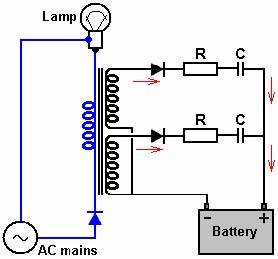
In this variation, the transformer
is wound with one primary and two secondary windings. The magnetic coupling of the transformer core
generates copies of the mains waveform in both of the secondary windings. Each are rectified and fed to the battery as
before.
If this circuit was being built
using standard off-the-shelf transformers, it might be easier to use two
separate transformers connected "in series". This would depend on the application and the
windings of the particular transformers to be used.
The diagrams show up to now have all suggested charging one or more batteries, but this has just been for the convenience of presenting a simple application. As is pointed out by Rosemary, it is perfectly possible to drive some other load such as a heater or a motor using these additional power take-off connections. However, for our continuing description of the circuit options, we will stay with battery charging. So, using two standard transformers, the circuit would be as shown here:
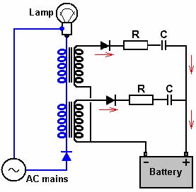
All of the Ainslie circuits
mentioned so far have used the mains, but there is very considerable scope for
circuits and arrangements which do not use the mains at all. Admittedly, a certain amount of electronic
construction work is needed, but the results can be very rewarding. For example, instead of charging a battery
bank, it is quite possible to charge the battery which is driving the circuit
itself.
Now, before you start to say that
this is an impossibility, please remember the little girl and her small
electric car battery. Her father found
that if he left the charging circuit on too long that he needed to put a bulb
in as a load in order to avoid over-charging the battery, and that battery
(appears to be) what powers the charging process. In all of these systems, please remember that
additional energy flows into the circuit from the local environment, so
charging a battery which is driving the circuit is perfectly possible. For example, Robert Adams of
Here is an Ainslie self-powering
circuit:
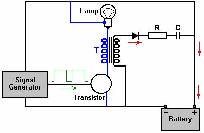
Here, the signal generator, which is
probably just a simple 555 timer circuit, produces a train of pulses with a
Mark-Space ratio of more than 50% On time.
That signal is used to switch a transistor On and Off in rapid
succession. The transistor type is
deliberately not shown as it can be an NPN silicon transistor, an FET type of
transistor, a
Obviously, all of the other options
and variations discussed above in connection with a mains-powered version of
the circuitry will apply equally well to a battery-powered version. If running from a battery or a bank of
batteries and high voltage is wanted, then an off-the-shelf inverter can be
used to generate the high voltage used for the mains supply.
If you would like to test the
operation of the circuit and the design generally, here is a stripboard layout
which might be used:
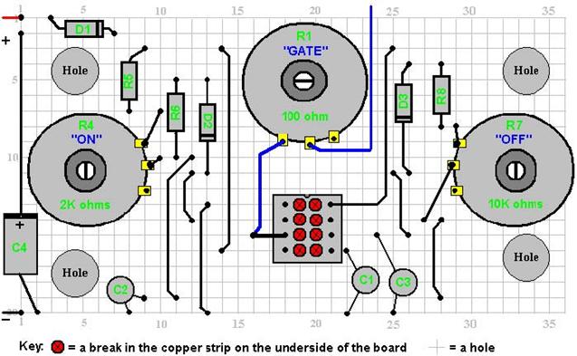
The preset resistors are high power
units looking like this:
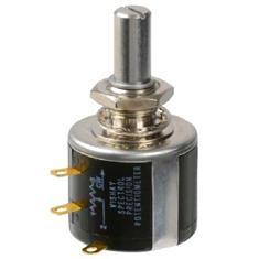
These are adjusted with a flat
screwdriver inserted into the slot at the end of the shaft although they could
have a knob attached. It takes ten full
turns of the shaft to move across the full range of the resistor. If you are adjusting the Mark-Space ratio and
the ratio goes up when you turn the shaft to the left but want that to happen
when you turn the shaft to the right, then just swap over the wires going to
the outermost terminals of the resistor and that will reverse the effect when
you turn the shaft. You can stick the
base of the resistor directly to the stripboard using "Impact"
Evostick or any similar adhesive and that will hold it securely but still allow
you to prise it off the board at a later date if you should need to.
There is no need to use knobs as the
circuit will be set up, adjusted for best performance and then left
untouched. The circuit can be built
using stripboard like this:
The view above is of the underside
of the board as that shows the copper strips running horizontally between the
holes. The copper strip is quite thin
and can easily be broken using the tip of a drill bit or alternatively, a
modelling knife. The spacing of the
holes is arranged to match the pin spacing of standard Integrated Circuits such
as the NE555 timer chip used in this circuit.
The only place where the strips need to be broken in the layout above
are between the pins of the NE555 chip and if you didn't do that, then the four
pairs of pins would be short-circuited together, preventing the chip from
operating. It is a good idea to use an
8-pin IC socket soldered to the board as that prevents any heat damage to the
NE555N chip during soldering, the IC being plugged in after the soldering has
cooled down. It also has the advantage
that if the chip ever gets damaged, then plugging another on in is a very easy
thing to do. After the board is
completed, it is also probably worth running a solder layer along the copper
strips which carry some current, that is the plus and minus strips and the strip
between pin 3 of the NE555N and the point where the connection to the variable
resistor is made. You will notice that
the layout of the board includes four holes to take mounting bolts. When these are drilled, the strips under the
board need to be cleared away to make sure that no short-circuits can occur
when the bolts are in place. The board
mounting is like this:
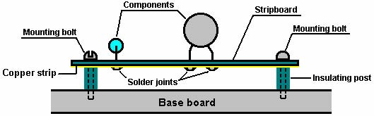
Suppose we wish to replicate and
test this circuit:
We need to remember that this is
just the outline for a practical circuit and that it does not show the normal
extra items like and On / Off switch and a fuse or circuit-breaker which are
essentials for any circuit which contains a powerful battery. Please remember that you can't see current
flow and if there is an accidental short-circuit, the first you may know of it
is smoke !! That tends to be expensive,
especially if some of the components are pricey and/or hard to get.
If we work with the Ainslie pulsing
circuit shown at the beginning of this document, then a physical layout
convenient for experimenting might be:
The "heat sink" shown in the diagram
above, is just a piece of aluminium bent to raise the centre section slightly and
allow good air circulation and clearance for the FET's locking nut. The FET is bolted securely to this plate in
order to allow the aluminium plate to let the FET run cooler than it otherwise
would. The lamp would be a 12V car type
and while many people just solder directly to the bulb as shown here, there is
no reason why a bulb socket should not be used.
Car accessory shops usually have low-cost "reversing lights"
which are a small plastic housing, a bulb socket, a bulb and two pieces of wire
already attached to the bulb holder - very convenient, especially since it is
very easy to change over to bulbs of different ratings for different tests and
the bulbs themselves are cheap.
This circuit is of course, the same as the driver circuit for the heating element circuit. The green link wire shown in the diagram above gets replaced with the 30-watt 0.25 ohm resistor and the resistor should be positioned so that it is in the air, well clear of everything else as it may get hot during operation in spite of its very low resistance value.
Disclaimer: It must be
understood that this document is presented for information purposes only and it
must not be construed as being an encouragement to either build or experiment
with this or any other circuit. The people
who have investigated, designed, built or described this circuitry are in no
way liable for any loss or damage caused by your actions, should you decide to
experiment with this or any other circuit.
Should you choose to do that, the responsibility for your actions rests
entirely with you alone. This document,
while presented in good faith, does not warrant that all attempted replications
of the circuits described in it will definitely perform in the same way as
those which were investigated during the tests which form the basis for this
description.
The Wood Gas Generator
Construction of a Simplified Wood Gas
Generator for Fueling Internal Combustion
Engines in a Petroleum Emergency

By:
H.
LaFontaine, Biomass Energy Foundation, lnc.
And:
F.
P. Zimmerman, Oak Ridge National Laboratory, Energy Division
FEMA
lnteragency Agreement Number: EMW-84-E-1737 Work Unit: 3521 D
For:
"This report has been reviewed
in the Federal Emergency Management Agency and approved for publication.
Approval does not signify that the contents necessarily reflect the views and
policies of the Federal Emergency Management Agency."
Date Published: March 1989 APPROVED FOR PUBLIC
RELEASE: DISTRIBUTION UNLIMITED
ABSTRACT:
CONSTRUCTION OF A SIMPLIFIED WOOD GAS GENERATOR FOR FUELING INTERNAL
COMBUSTION ENGINES IN A PETROLEUM EMERGENCY
H. LaFontaine, G. P. Zimmerman
This
report is one in a series of emergency technology assessments sponsored by the
Federal Emergency Management Agency (FEMA). The purpose of this report is to
develop detailed, illustrated instructions for the fabrication, installation,
and operation of a biomass gasifier unit (i.e., a 'producer gas' generator,
also called a "wood gas' generator) that is capable of providing emergency
fuel for vehicles, such as tractors and trucks, in the event that normal
petroleum sources were severely disrupted for an extended period of time. These
instructions have been prepared as a manual for use by any mechanic who is
reasonably proficient in metal fabrication or engine repair. This report attempts to preserve the
knowledge about wood gasification that was put into practical use during World
War II. Detailed, step-by-step fabrication procedures are presented for a
simplified version of the World War II, Embowered wood gas generator. This
simple, stratified, downdraft gasifier unit can be constructed from materials
that would be widely available in the
Executive Summary
This
report is one in a series of emergency technology assessments sponsored by the
Federal Emergency Management Agency (FEMA). The purpose of this report is to
develop detailed, illustrated instructions for the fabrication, installation,
and operation of a biomass gasifier unit (i.e. a "producer gas"
generator, also called a "wood gas" generator) which is capable of
providing emergency fuel for vehicles, such as tractors and trucks, should
normal petroleum sources be severely disrupted for an extended period of
time. These instructions have been
prepared as a manual for use by any mechanic who is reasonably proficient in
metal fabrication or engine repair.
Fuel
gas, produced by the reduction of coal and peat, was used for heating as early
as 1840 in Europe and by 1884 had been adapted to fuel engines in
However,
a catastrophic event could disrupt the supply of petroleum in this country so
severely that this technology might be critical in meeting the energy needs of
some essential economic activities, such as the production and distribution of
food. In occupied
Because
of the wood gasifier’s health risks from toxic fumes, most of such units were
abandoned when oil again became available in 1945. Except for the technology of
producing alternate fuels, such as methane or alcohol, the only solution for
operating existing internal combustion engines, when oil and petroleum products
are not available, has been these simple, inexpensive Gasifier units.
This
report attempts to preserve the knowledge about wood gasification that was put
into practical use during World War II. In this report, detailed step-by-step
procedures are presented for constructing a simplified version of the WWII wood
gas generator; this simple, stratified, downdraft Gasifier unit (shown
schematically in Fig.S-1) can be constructed from materials which would be
widely available in the
These
wood gas generators need not be limited to transportation applications.
Stationary engines can also be fueled by wood gasifiers to run electric
generators, pumps, and industrial equipment. In fact, the use of wood gas as a
fuel is not even restricted to gasoline engines; if a small amount of diesel
fuel is used for ignition, a properly adjusted diesel engine can be operated
primarily on wood gas introduced through the intake manifold.
Principles of solid fuel gasification
All
internal combustion engines actually run on vapor, not liquid. The liquid fuels
used by gasoline engines are vaporized before they enter the combustion chamber
above the pistons. In diesel engines, the fuel is sprayed into the combustion
chamber as fine droplets which burn as they vaporize.
The
purpose of a Gasifier, then, is to transform solid fuels into gaseous ones and
to keep the gas free of harmful constituents. A gas generator unit is
simultaneously an energy converter and a filter. In these twin tasks lie its
advantages and its difficulties. In a sense, gasification is a form of
incomplete combustion-heat from the burning solid fuel creates gases which are
unable to burn completely because of the insufficient amounts of oxygen from
the available supply of air. The same chemical laws which govern combustion
processes also apply to gasification.
There
are many solid biomass fuels suitable for gasification - from wood and paper to
peat, lignite, and coal, including coke derived from coal. All of these solid
fuels are composed primarily of carbon with varying amounts of hydrogen,
oxygen, and impurities, such as sulfur, ash, and moisture. Thus, the aim of
gasification is the almost complete transformation of these constituents into
gaseous form so that only the ashes and inert materials remain. In creating
wood gas for fueling internal combustion engines, it is important that the gas
not only be properly produced, but also preserved and not consumed until it is
introduced into the engine where it may be appropriately burned.
Gasification
is a physicochemical process in which chemical transformations occur along with
the conversion of energy. The chemical reactions and thermochemical conversions
which occur inside a wood gas generator are too long and too complicated to be
covered here; however, such knowledge is not necessary for constructing and
operating a wood Gasifier. By weight, gas (wood gas) produced in a Gasifier
unit contains approximately 20% hydrogen (H2), 20% carbon monoxide
(CO), and small amounts of methane, all of which are combustible, plus 50 to
60% nitrogen (N2). The nitrogen is not combustible; however, it does
occupy volume and dilutes the wood gas as it enters and burns in an engine. As
the wood gas burns, the products of combustion are carbon dioxide (CO2)
and water vapor (H20).
One
of the by-products of wood gasification is carbon monoxide, a poisonous gas.
The toxic hazards associated with breathing this gas should be avoided during
refueling operations or prolonged idling, particularly in inadequately
ventilated areas. Except for the obvious fire hazard resulting from the
combustion processes inside the unit, carbon monoxide poisoning is the major
potential hazard during normal operation of these simplified Gasifier units.
THE STRATIFIED DOWNDRAFT GASIFIER
Until
the early 1980s, wood gasifiers all over the world (including the World War II
designs) operated on the principle that both the fuel hopper and the combustion
unit be absolutely airtight; the hopper was sealed with a top or lid which had
to be opened every time wood was added. Smoke and gas vented into the
atmosphere while wood was being loaded; the operator had to be careful not to
breathe the unpleasant smoke and toxic fumes.
Over
the last few years, a new Gasifier design has been developed through
cooperative efforts among researchers at the Solar Energy Research Institute in
A
schematic diagram of the stratified, downdraft Gasifier is shown in Fig.
S-1.During operation of this Gasifier, air passes uniformly downward through
four zones, hence the name stratified:
1
The uppermost zone
contains unreacted fuel through which air and oxygen enter. This region serves
the same function as the fuel hopper in the older, World War II designs.
2
In the second zone, the wood fuel reacts with
oxygen during pyrolysis. Most of the volatile components of the fuel are burned
in this zone and provide heat for continued pyrolysis reactions. At the bottom
of this zone, all of the available oxygen from the air should be completely
reacted. The open top design ensures uniform access of air to the pyrolysis
region.
3
The third zone is made up of charcoal from the
second zone. Hot combustion gases from the pyrolysis region react with the charcoal
to convert the carbon dioxide and water vapor into carbon monoxide and
hydrogen.
4
The inert char and
ash, which constitute the fourth zone, are normally too cool to cause further
reactions; however, because the fourth zone is available to absorb heat or
oxygen as conditions change, it serves both as a buffer and as a charcoal
storage region. Below this zone is the grate. The presence of char and ash
serves to protect the grate from excessive temperatures.
The
stratified, downdraft design has a number of advantages over the World War II
gasifier designs. The open top permits fuel to be fed more easily and allows
easy access. The cylindrical shape is easy to fabricate and permits continuous
flow of fuel. No special fuel shape or pretreatment is necessary; any blocky
fuel can be used.
The
foremost question about the operation of the stratified, downdraft gasifier
concerns char and ash removal. As the charcoal reacts with the combustion
gases, it eventually reaches a very low density and breaks up into a dust
containing all of the ash as well as a percentage of the original carbon. This
dust may be partially carried away by the gas and might eventually begin to
plug the gasifier. Hence, it must be removed by shaking or agitation. When the
stratified gasifier unit is used to power vehicles, it is automatically shaken
by the vehicle's motion.
An
important issue in the design of the stratified, downdraft gasifier is the
prevention of fuel bridging and channeling. High-grade biomass fuels, such as
wood blocks or chips, will flow down through the gasifier because of gravity
and downdraft air flow. However, other fuels (such as shredded chips, sawdust,
and bark) can form a bridge, which will obstruct continuous flow and cause very
high temperatures. Bridging can be prevented by stirring, shaking, or by
agitating the grate or by having it agitated by the vehicle's movement. For
prolonged idling, a hand-operated shaker has been included in the design in
this report.
A
prototype unit of the stratified, downdraft gasifier design (see Figs. S-2 and
S-3) has been fabricated according to the instructions in this report; however,
it has not been widely tested at this time. The reader is urged to use his
ingenuity and initiative in the construction of his own wood gas generator. As
long as the principle of air tightness in the combustion regions, in the
connecting piping, and in the filter units is followed, the form, shape, and
method of assembly is not important.
The
wood gasifier design presented in this report has as its origin the proven
technology used in World War II during actual shortages of gasoline and diesel
fuel. It should be acknowledged that there are alternate technologies (such as
methane production or use of alcohol fuels) for keeping internal combustion
engines in operation during a prolonged petroleum crisis; the wood gasifier
unit described in this report represents only one solution to the problem.
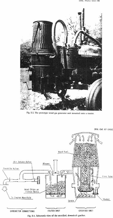
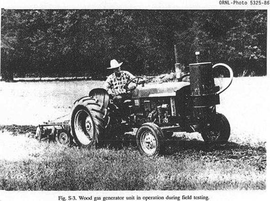
WHAT IS A WOOD GAS
GENERATOR AND HOW DOES IT WORK?
This
report is one in a series of emergency technology assessments sponsored by the
Federal Emergency Management Agency (FEMA).
The purpose of this report is to develop detailed, illustrated
instructions for the fabrication, installation, and operation of a biomass
gasifier unit (i.e., a "producer gas" generator, also called a 'wood
gas' generator) that is capable of providing emergeney fuel for vehicles, such
as tractors and trucks, in the event that normal petroleum sources were severely
disrupted for an extended period of time.
These instructions have been prepared as a manual for use by any
mechanic who is reasonably proficient in metal fabrication or engine repair.
INTRODUCTION
Fuel
gas, produced by the reduction of coal and peat, was used for heating, as early
as 1840 in Europe, and by 1884 it had been adapted to fuel engines in
The
United States, never faced with such prolonged or severe oil shortages, has lagged
far behind Europe and the Orient in familiarity with and application of this
technology; however, a catastrophe could so severely disrupt the supply of
petroleum in this country that this technology might be critical in meeting the
energy needs of some essential economic activities, such as the production and
distribution of food. This report attempts to preserve the knowledge about wood
gasification as put into practical use during World War II. Detailed,
step-by-step procedures are presented in this report for constructing a
simplified version of the World War II, Imbert wood gas generator.
This
simple, stratified, downdraft gasifier unit can be constructed from materials
that would be widely available in the
The
use of wood gas generators need not be limited to transportation applications.
Stationary engines can also be fueled by wood gasifiers to run electric
generators, pumps, and industrial equipment. In fact, the use of wood gas as a
fuel is not even restricted to gasoline engines; if a small amount of diesel
fuel is used for ignition, a properly adjusted diesel engine can be operated
primarily on wood gas introduced through the intake manifold.
However,
this report is concerned with the operation of four-cylinder gasoline engines
rated from 10 to 150 horsepower. If more
information is needed about operating gasifiers on other fuels (such as coal,
charcoal, peat, sawdust or seaweed), a list of relevant literature is contained
in the Bibliography at the end of this report.
The
goal of this report is to furnish information for building a homemade wood gas
generator made out of ordinary, available hardware, in order to get tractors,
trucks, and other vehicles operating without delay, if a severe liquid fuel
emergency should arise. Section 1
describes gasification principies and wood gas generators, in general, and
gives some historical background about their operation and effectiveness. Section 2 contains detailed step-by-step
instructions for constructing your own wood gas generator unit; illustrations
and photographs are inciuded to prevent confusion. Section 3 contains information on operating,
maintaining, and trouble-shooting your wood gas generator; also included are
some very important guidelines on safety when using your gasifier system.
The
wood gasifier design presented in this report has as its origin the proven
technology used in World War II during actual shortages of gasoline and diesel
fuel. It should be acknowledged that
there are alternate technologies (such as methane production or use of alcohol
fuels) for keeping internal combustion engines in operation during a prolonged
petroleum crisis; the wood gasifier unit described in this report represents
only one solution to the problem.
PRINCIPLES OF SOLID FUEL
GASIFICATION
All
internal combustion engines actually run on vapor, not liquid. The liquid fuels used in gasoline engines are
vaporized before they enter the combustion chamber above the pistons. In diesel
engines, the fuel is sprayed into the combustion chamber as fine droplets which
burn as they vaporize. The purpose of a
gasifier, then, is to transform solid fuels into gaseous ones and to keep the
gas free of harmful constituents. A gas
generator unit is, simultaneously, an energy converter and a filter. In these
twin tasks lie its advantages and its difficulties.
The
first question many people ask about gasifiers is, 'Where does the combustible
gas come from?' Light a wooden match;
hold it in a horizontal position; and notice that while the wood becomes
charcoal, it is not actually burning but is releasing a gas that begins to burn
brightly a short distance away from the matchstick. Notice the gap between the matchstick and the
luminous flame; this gap contains the wood gas which starts burning only when
properly mixed with air (which contains oxygen).
By
weight, this gas (wood gas) from the charring wood contains approximately 20%
hydrogen (H2), 20% carbon monoxide (CO), and small amounts of
methane, all of which are combustible, plus 50 to 60% nitrogen (N2). The nitrogen is not combustible; however, it
does occupy volume and dilutes the wood gas as it enters and burns in an
engine. As the wood gas burns, the
products of combustion are carbon dioxide (CO2) and water vapor (H2O).
The
same chemical laws which govern combustion processes also apply to gasification.
The solid, biomass fuels suitable for gasification cover a wide range, from
wood and paper to peat, lignite, and coal, including coke derived from
coal. All of these solid fuels are
composed primarily of carbon with varying amounts of hydrogen, oxygen, and
impurities, such as sulphur, ash, and moisture.
Thus, the aim of gasification is the almost complete transformation of
these constituents into gaseous form so that only the ashes and inert materials
remain.
In
a sense, gasification is a form of incomplete combustion; heat from the burning
solid fuel creates gases which are unable to burn completely, due to
insufficient amounts of oxygen from the available supply of air.
In the matchstick example above, as
the wood was burned and pyrolyzed into charcoal, wood gas was created, but the
gas was also consumed by combustion (since there was an enormous supply of air
in the room).
In
creating wood gas for fueling internal combustion engines, it is important that
the gas not only be properly produced, but also preserved and not consumed
until it is introduced into the engine where it may be appropriately
burned. Gasification is a
physicochemical process in which chemical transformations occur along with the
conversion of energy. The chemical reactions
and thermochemical conversions which occur inside a wood gas generator are too
long and too complicated to be covered here. Such knowledge is not necessary
for constructing and operating a wood Gasifier.
Books with such information are listed in the Reference Section (see,
for example, Reed 1979, Vol. II; or Reed and Das 1988).
BACKGROUND INFORMATION
The
use of wood to provide heat is as old as mankind; but by burning the wood we
only utilize about one-third of its energy.
Two-thirds is lost into the environment with the smoke. Gasification is
a method of collecting the smoke and its combustible components. Making a combustible gas from coal and wood
began around 1790 in
Wood
gas generators are not technological marvels that can totally eliminate our
current dependence on oil, reduce the impacts of an energy crunch, or produce
long-term economic relief from high fossil fuel prices, but they are a proven
emergency solution when such fuels become unobtainable in case of war, civil
upheaval, or natural disaster. In fact,
many people can recall a widespread use of wood gas generators during World War
II, when petroleum products were not available for the civilian populations in
many countries. Naturally, the people
most affected by oil and petroleum scarcity made the greatest advancements in
wood gas generator technology.
In
occupied
Because
of the wood gasifier's somewhat low efficiency, the inconvenience of operation,
and the potential health risks from toxic fumes, most of such units were
abandoned when oil again became available in 1945. Except for the technology of
producing alternate fuels, such as methane or alcohol, the only solution for
operating existing internal combustion engines, when oil and petroleum products
are not available, has been these simple, inexpensive Gasifier units.
The World War II, Imbert
Gasifier
The
basis operation of two gasifiers is described in this and the following
section. Their operating advantages and disadvantages will also be
discussed. This information is included
for the technically interested reader only; it is intended to give the reader
more insight into the subtleties of the operating principles of the wood gas
generator described in this manual.
Those readers who are anxious to begin construction of their own wood
gas generator may skip the material below and proceed directly to Sec.2 without
any loss of continuity.
The
constricted hearth, downdraft Gasifier shown in Fig. 1-2 is sometimes called
the 'Imbert' Gasifier after its inventor, Jacques Imbert; although, it has been
commercially manufactured under various names.
Such units were mass-produced during World War II by many European
automotive companies, including General Motors, Ford, and Mercedes-Benz. These
units cost about $1500 (1985 evaluation) each.
However,
after World War II began in 1939, it took six to eight months before
factory-made gasifiers were generally available. Thousands of Europeans were saved from
certain starvation by home-built, simple Gasifier units made from washing
machine tubs, old water heaters, and metal gas or oxygen cylinders. Surprisingly, the operation of these units
was nearly as efficient as the factory-made units; however, the homemade units
lasted for only about 20000 miles with many repairs, while the factory-made
units operated, with few repairs, up to 100,000 miles.
In
Fig. 1-2 the upper cylindrical portion of the Gasifier unit is simply a storage
bin or hopper for wood chips or other biomass fuel. During operation, this chamber is filled
every few hours as needed. The
spring-loaded, airtight cover must be opened to refill the fuel hopper; it must
remain closed and sealed during Gasifier operation. The spring permits the cover to function as a
safety valve because it will pop open in case of any excessive internal gas
pressure.
About
one-third of the way up from the bottom of the Gasifier unit, there is a set of
radially directed air nozzles; these allow air to be injected into the wood as it
moves downward to be gasified. In a gas
generator for vehicle use, the down stroke of the engine's pistons creates the
suction force which moves the air into and through the Gasifier unit; during
startup of the Gasifier, a blower is used to create the proper airflow. The gas is introduced into the engine and
consumed a few seconds after it is made.
This gasification method is called "producer gas generation,"
because no storage system is used; only that amount of gas demanded by the
engine is produced. When the, engine is shut off, the production of gas stops.
During
normal operation, the incoming air burns and pyrolyzes some of the wood, most
of the tars and oils, and some of the charcoal that fills the constricted area
below the nozzles. Most of the fuel mass is converted to gas within this
combustion zone. The Imbert Gasifier is,
in many ways, self-adjusting. If there
is insufficient charcoal at the air nozzles, more wood is burned and pyrolyzed
to make more charcoal. If too much
charcoal forms, then the charcoal level rises above the nozzles, and the
incoming air burns the charcoal. Thus, the combustion zone is maintained very
close to the nozzles.
Below
this combustion zone, the resulting hot combustion gases - carbon dioxide (CO2)
and water vapor (H2O) - pass into the hot charcoal where they are
chemically reduced to combustible fuel gases: carbon monoxide (CO) and hydrogen
(H2).
The hearth constriction causes all gases to
pass through the reaction zone, thus giving maximum mixing and minimum heat
loss. The highest temperatures are reached in this region.
Fine
char and ash dust can eventually clog the charcoal bed and will reduce the gas
flow unless the dust is removed. The charcoal is supported by a movable grate
which can be shaken at intervals. Ash
buildup below the grate can be removed during cleaning operations. Usually, wood contains less than 1% ash (by
weight). However, as the charcoal is
consumed, it eventually collapses to form a powdery charcoal/ash mixture which
may represent 2 to 10% (by weight) of the total fuel mass.
The
cooling unit required for the lmbert Gasifier consists of a water filled
precipitating tank and an automotive radiator type gas cooler. The precipitating tank removes all
unacceptable tars and most of the fine ash from the gas flow, while the
radiator further cools the gas. A second
filter unit, containing a fine mesh filtration material, is used to remove the
last traces of any ash or dust that may have survived passage through the
cooling unit. Once out of the filter
unit, the wood gas is mixed with air in the vehicle's carburetor and is then
introduced directly into the engine's intake manifold.
The
World War II, Imbert Gasifier requires wood with a low moisture content (less
than 20% by weight) and a uniform, blocky fuel in order to allow easy gravity
feed through the constricted hearth.
Twigs, sticks, and bark shreds cannot be used. The constriction at the
hearth and the protruding air nozzles present obstructions to the passage of
the fuel and may create bridging and channeling followed by poor quality gas
output, as unpyrolyzed fuel falls into the reaction zone. The vehicle units of
the World War II era had ample vibration to jar the carefully sized wood blocks
through the Gasifier.
In
fact, an entire industry emerged for preparing wood for use in vehicles at that
time (Reed and Jantzen 1979). However, the constricted hearth design seriously
limits the range of wood fuel shapes that can be successfully gasified without
expensive cubing or pelletizing pretreatment. It is this limitation that makes
the Imbert Gasifier less flexible for emergency use. In summary, the World War II Imbert Gasifier
design has stood the test of time and has successfully been mass produced. It is relatively inexpensive, uses simple
construction materials, is easy to fabricate, and can be operated by motorists
with a minimum amount of training.
The Stratified, Downdraft
Gasifier
Until
the early 1980's, wood gasifiers all over the world (including the World War II
designs) operated on the principle that both the fuel hopper and the combustion
unit be airtight; the hopper was sealed with a top or lid that bad to be opened
every time wood was added. Smoke and gas vented into the atmosphere while new
wood was being loaded; the operator bad to be careful not to breathe the
unpleasant smoke and toxic fumes.
Over
the last few years, a new gasifier design bas been developed through
cooperative efforts among researchers at the Solar Energy Research Institute in
Colorado, the University of California in Davis, the Open University in London,
the Buck Rogers Company in Kansas, and the Biomass Energy Foundation, Inc., in
Florida (Reed and Das 1988). This simplified design employs a balanced,
negative-pressure concept in which the old type of sealed fuel hopper is no
longer necessary. A closure is only used
to preserve the fuel when the engine is stopped.
This
new technology has several popular names, including 'stratified, downdraft
gasification' and 'open top gasification.'
Two years of laboratory and field testing have indicated that such
simple, inexpensive gasifiers can be built from existing hardware and will
perform very well as emergency units. A
schematic diagram of the stratified, downdraft Gasifier is shown in Fig.
1-3. During operation of this gasifier,
air passes uniformly downward through four zones, hence the name 'stratified:'
1.
The uppermost zone contains
unreacted fuel through which air and oxygen enter. This region serves the same
function as the fuel hopper in the Imbert design.
2. In the
second zone, the wood fuel reacts with oxygen during pyrolysis. Most of the
volatile components of the fuel are burned in this zone and provide heat for continued
pyrolysis reactions. At the bottom of this zone, all of the available oxygen
from the air bas completely reacted. The open top design ensures uniform access
of air to the pyrolysis region.
3. The third
zone is made up of charcoal from the second zone. Hot combustion gases from the
pyrolysis region react with the charcoal to convert the carbon dioxide and
water vapor into carbon monoxide and hydrogen.
4. The inert
char and ash, which constitute the fourth zone, are normally too cool to cause
further reactions; however, since the fourth zone is available to absorb heat
or oxygen as conditions change, it serves both as a buffer and as a charcoal
storage region. Below this zone is the grate. The presence of char and ash
serves to protect the grate from excessive temperatures.
The
stratified, downdraft design has a number of advantages over the World War II,
Imbert Gasifier. The open top permits
fuel to be fed more easily and allows easy access. The cylindrical shape is
easy to fabricate and permits continuous flow of fuel. No special fuel shape or pretreatment is
necessary; any blocky fuel can be used.
The
foremost question about the operation of the stratified, downdraft Gasifier
concerns char and ash removal. As the
charcoal reacts with the combustion gases, it eventually reaches a very low
density and breaks up into a dust containing all of the ash as well as a
percentage of the original carbon. This
dust may be partially carried away by the gas; however, it might eventually
begin to plug the Gasifier, and so it must be removed by shaking or
agitation. Both the Imbert gasifiers and
the stratified concept have a provision for shaking the grate; when they are
used to power vehicles, they are automatically shaken by the vehicle's motion.
An
important issue in the design of the stratified, downdraft gasifier is the
prevention of fuel bridging and channeling.
High-grade biomass fuels such as wood blocks or chips will flow down
through the gasifier under the influence of gravity, and downdraft air
flow. However, other fuels (such as
shredded wood, sawdust, and bark) can form a bridge that will prevent
continuous flow and cause very high temperatures. Obviously, it is desirable to use these
widely available biomass residues. Bridging can be prevented by stirring,
shaking, or by agitating the grate or by having it agitated by the vehicle's
movement. For prolonged idling, a hand-operated shaker has been included in the
design.
A prototype design of the stratified, downdraft gasifier design has been developed. The detailed but simple design is described and illustrated in Sect. 2; however, it has not been widely tested at this time. The reader is urged to use his ingenuity and initiative in constructing his own wood gas generator. As long as the principle of air-tightness in the combustion regions, in the connecting piping, and in the filter units is followed, the form, shape, and method of assembly is not important.
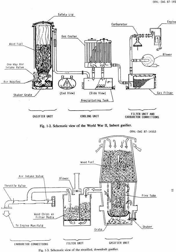
BUILDING YOUR OWN WOOD
GAS GENERATOR
The
following fabrication instructions, parts lists, and illustrations describe the
prototype Gasifier unit shown schematically in Fig. 1-3. These instructions are simple and easy to
follow. The dimensions in the following plans are given in inches rather than
in millimeters to make construction easier for those who might be unfamiliar
with the metric system and to allow the builder to take advantage of available,
alternate construction materials. It
will be obvious to the experienced engineer, mechanic, or builder that most of
the dimensions (for example, plate thicknesses and clean-out diameters) are not
critical to the acceptable performance of the finished Gasifier unit.
The
prototype Gasifier unit described in the following text was actually
constructed and field tested on a gasoline engine farm tractor (a 35-hp, John
Deere 1010 Special); see Fig. 2-1. The unit operated very well, and on par with
the European, World War II designs, but it has not had the test of time nor the
millions of operating hours like the older Imbert design. This new stratified design was developed for
the construction of simple, inexpensive emergency wood gas generator
units. The prototype design below should
be considered to be the absolute minimum in regard to materials, piping and
filter arrangement, and carburetor system connections.
The
Gasifier unit, as described below, is designed to maintain proper cooling, even
at moderate vehicle speeds. If this unit is to be used on stationary engines or
on slow-moving vehicles, a gas cooler and a secondary filter must be placed in
the piping system between the generator unit and the carburetor. The ideal temperature for the wood gas at the
inlet to the carburetor manifold would be 70oF, with acceptable
peaks of 140 to 160oF. For
every 10 degrees above 70oF, an estimated 1% horsepower is
lost. Cooler gas has higher density and,
therefore, contains more combustible components per unit volume.
The
millions of wood gasifiers built during World War II proved that shape, form,
and construction material bad little or no effect on the performance of the
unit. Judicious substitution or the use
of scavenged parts is, therefore, quite acceptable. What is important is that:
1
The fire tube
dimensions (inside diameter and length) must be correctly selected to match the
rated horsepower of particular engine which is to be fueled,
2
Air-tightness of the gas generator unit and
all connecting piping must be maintained at all times, and
3
Unnecessary friction should be eliminated in
all of the air and gas passages by avoiding sharp bends in the piping and by
using piping sizes which are not too small.
BUILDING THE GAS
GENERATOR UNIT AND THE FUEL HOPPER
Figure
2-2 shows an exploded view of the gas generator unit and the fuel hopper; the
list of materials is given in Table 2-1 (all figures and tables mentioned in
Sect. 2 are presented at the end of Sect. 2).
Only the dimensions of the fire tube (Item lA) must be reasonably close;
all other dimensions and materials can be substituted as long as complete
air-tightness is maintained. In the following instructions, all item numbers
refer both to Fig. 2-2 and to Table 2-1.
The
prototype unit described in this report was constructed for use with a 35-hp
gasoline engine; the unit has a fire tube diameter of 6 in. (as determined from
Table 2-2). A gas generator unit
containing a fire tube up to 9-in. diameter (i.e., a gasifier unit for fueling
engines up to about 65 hp) can be constructed from the following instructions. If your engine requires a fire tube diameter
of 10 in. or more, use a 55-gal drum for the gas unit and another 55-gal drum
for the fuel hopper.
The
following fabrication procedure is very general and can be applied to the
construction of gas generator units of any size; however, the specific
dimensions which are given in the parts list and in the instructions below are
for this particular prototype unit. All accompanying photographs were taken
during the actual assembly of the prototype unit. The fabrication procedure is
as follows:
1
Using the displacement or horsepower rating of
the engine to be fueled by the gasifier unit, determine the dimensions (inside
diameter and length) of the fire tube (Item lA) from Table 2-2. Fabricate a
cylindrical tube or cut a length of correctly sized pipe to match the
dimensions from Table 2-2. (For the prototype gasifier unit illustrated in this
report, a 6-in.-diam firetube was used; its length was 19 in.)
2
The circular top plate (Item 2A) should be cut
to a diameter equal to the outside diameter of the Gasifier housing drum (Item
3A) at its top. A circular hole should
then be cut in the center of the top plate; the diameter of this hole must be
equal to the outside diameter of the fire tube.
The fire tube (Item 1A) should then be welded at a right angle to the
top plate (Item 2A) as shown in Fig. 2-3.
3
The grate (Item 4A) should be made from a
stainless steel mixing bowl or colander. Approximately 125 holes with diameters
of ½ in. should be drilled in the bottom and up the sides of the mixing bowl;
see Fig. 2-4. A U-bolt (Item 5A) should
be welded horizontally to the side of the grate, 2 inches from its bottom. This U-bolt will be interlocked with the
shaker mechanism (Item 12A) in a later step.
4
The support chains (Item 6A) are to be attached
to the grate in three evenly spaced holes drilled under the lip of the mixing
bowl or colander; see Fig. 2-5. These
chains are to be connected to the top plate (Item 2A) with eye bolts (Item 7A),
as shown in Fig. 2-6. Each eyebolt
should have two nuts, one on each side of the top plate, so that the eye bolts
can be adjusted to the proper length.
When assembled, the bottom of the firetube should be 1.25 in. above the
bottom of the mixing bowl.
5
A hole equal to the outside diameter of the
ash clean out port (Item SA) should be cut into the side of the gasifier
housing drum (Item 3A); the bottom edge of this hole should be about ½ in. from
the bottom of the drum. Because of the
thin wall thickness of oil drums and garbage cans, welding is not recommended;
brazing such parts to the drums or cans will ensure both strength and
airtightness (see Fig. 2-7).
6
Two holes, equal to the outside diameters of
the ignition ports (Item 10A), are to be cut with their centers at a distance
from the top of the housing drum (Item 3A) equal to the firetube length less 7
in. (19 in. less 7 in. equals 12 in. for this prototype unit); the holes should
be placed opposite each other as shown in Fig. 2-2. The ignition ports should be attached to the
wall of the housing drum by brazing.
7
When the ash clean out port (Item 8A) and the
ignition ports (Item 10A) have been attached to the wall of the gasifier
housing drum (Item 3A), they should then be closed with pipe caps, Items 9A and
11A respectively. The threads of the pipe
caps should be first coated with high temperature silicone (Item 27A) to ensure
airtightness. An optional steel crossbar
welded to the pipe cap will reduce the effort required to open these caps
later.
8
The shaker assembly (Item 12A) is shown in
Fig. 2-8. The 1/2-in. pipe (Item 1AA)
should be brazed into the side of the housing drum (Item 3A), 1.5 inches from
the bottom of the drum; the length of this pipe which protrudes into the drum
must be chosen so that the upright bar (Item 2AA) is in line with the U-bolt
(Item 5A) on the grate. Likewise, the
length of the upright bar must be selected so as to connect into the U-bolt.
9
Weld the upright bar (Item 2AA) to the head of
the bolt (Item 3AA). The threaded end of the bolt should be ground down or
flattened on one side, as shown in Fig. 2-9, to positively interlock with a
slot to be drilled and filed in the handle (Item 4AA). The handle can be formed or bent into any
desired or convenient shape.
10
A hole should be drilled in the pipe cap (Item
7AA) so that there is a close fit between this hole and the bolt (Item
3AA). The close fit will help to ensure
air-tightness.
11
Before assembling the shaker, as shown in Fig.
2-8, coat the bolt (Item 3AA) with a small amount of grease. Before inserting the bolt, fill the pipe
(Item lAA) with high temperature silicone (Item 27A) to ensure
air-tightness. Tighten the nuts (Item
6AA) so that the position of the handle (Item 4AA) is maintained by friction,
yet is capable of being turned and agitated during clean-out or stationary
operation.
12
Fabricate the supports (Item 13A) for the
Gasifier unit housing drum (Item 3A) out of rectangular, iron bar stock. The shape and height of the support flanges
must be determined by the frame of the vehicle to which the gasifier is to be
mounted. The supports can either be
bolted to the bottom and side with the 114-in. bolts (Item 14A) or can be
brazed directly to the drum; see Fig. 2-10.
Remember to seal all bolt holes for air-tightness.
13
Completely cover the bottom of the housing
drum (Item 3A) with ½ in. of hydraulic cement (Item 28A). The cement should also be applied to the
inside of the drum for about 5 inches up the inside walls near the bottom. All edges should be rounded for easy ash
removal.
14
The fuel hopper (Item 15A) is to be made from
a second container with its bottom up as shown in Fig. 2-11. Remove the bottom, leaving a 1/4-in. lip
around the circumference.
15
A garden hose (Item 17A) should be cut to a
length equal to the circumference of the fuel hopper (Item 15A) and should then
be, slit along its entire length. It
should be placed over the edge of the fuel hopper from which the bottom was
removed. This will prevent injury to the
operator when adding wood fuel to the unit.
To insure close fit of the garbage can lid (Item 16A), a piece of
weather stripping (Item 18A) should be attached under the lid where it makes
contact with the fuel hopper.
16
Cut four support bars (Item 19A) to lengths
2.5 in. longer than the height of the fuel hopper (Item 15A). Drill a 3/8-in. hole in each end of all four
support bars; these holes should be centered 3/4 in. from the ends. Bend 2 in. of each end of these support bars
over at a right angle; then, mount them evenly spaced around the fuel hopper
(Item 15A) with 1/4-in. bolts (Item 20A). One of the bends on each support bar
should be as close to the lower edge of the fuel hopper as possible.
17
Cut four metal triangular standoffs (Item 21A)
and braze, weld, or rivet them flat against the edge of the garbage can lid
(Item 16A) as shown in Fig. 2-12; they must be aligned with the four support
bars (Item 19A) attached to the fuel hopper.
During operation, the garbage can lid must have a minimum 3/4-in.
opening for air passage; the standoffs should provide this clearance, where they
are engaged into the holes in the top edges of the support bars (Item 19A); see
Fig. 2-13.
18
Two eye-hooks (Item 22A) should be attached to
opposite sides of the garbage can lid (Item 16A). Two screen door springs (Item 23A) should be
attached to the garbage can handle-s and used under tension to keep the top lid
(Item 16A) either open or closed.
19
Cut the oil drum lock ring (Item 24A) to the
exact circumference of the top plate (Item 2A) so that it will fit snugly
around the Gasifier unit housing drum (Item 3A).
20
Cut four 2 by 2 by 1/4-in. tabs (Item 25A);
then, braze these tabs to the lock ring (Item 24A), evenly spaced and in
alignment with the support bars (Item 19A) on the fuel hopper. Drill a 3/8-in.
hole in each tab to align with the holes in the fuel hopper support bars (Item
19A). The lock ring is shown in Fig. 2-14.
21
The connecting pipe (Item 29A) between the
Gasifier unit and the filter unit should be attached to the gasifier housing
drum (Item 3A) at a point 6 in. below the top of the drum. This pipe must be a
minimum of 2-in. in diameter and should be at least 6 ft long for cooling
purposes. At least one of the ends of this pipe must be removable for cleaning
and maintenance. On this prototype unit, an airtight electrical conduit
connector was used; this connection is visible in Fig. 2-1. Many similar plumbing devices are available
and can be used if they are suitable for operation at 400 F and above. The pipe can also be welded or brazed
directly to the housing drum.
22
When assembling the Gasifier unit, the upright
bar (Item 2AA) on the shaker assembly must be placed inside the U-bolt (Item
5A) on the grate.
23
The lock ring will then clamp the gasifier
unit housing drum (Item 3A) and the top plate (Item 2A) together. The fuel
hopper support bars (Item 19A) must be attached to the tabs (Item 25A) on the
lock ring with bolts (Item 26A). High
temperature silicone (Item 27A) should be applied to all edges to make an
airtight connection. The lock ring
connections are shown in the lower portion of Fig. 2-13.
BUILDING THE PRIMARY
FILTER UNIT
Figures
2-15 and 2-16 show exploded views of the primary filter unit; the list of
materials is given in Table 2-3 (all figures and tables mentioned in Sect. 2
are presented at the end of Sect. 2). In
the following instructions, all item numbers refer to either Fig. 2-15 or 2-16
and to Table 2-3.
The
prototype primary filter unit was made from a 5-gal paint can. That size seems to be sufficient for
gasifiers with fire tubes up to 10 in. in diameter. If a fire tube diameter of more than 10 in.
is required, then a 20-gal garbage can or a 30-gal oil drum should be
used. The Filter unit could be
fabricated in any shape or form as long as air-tightness and unobstructed flow
of gas are provided. If a 5-gal
container is used, it must be clean and free of any chemical residue. The top
edge must be straight and without any indentations. If an alternate container can be found or
fabricated, a larger diameter will permit longer operation between cleanings.
The
piping (Item 29A in Figs 2-2 and 2-15) which connects the gas generator unit to
the primary filter should be considered to be a necessary part of the cooling
system and should never have an inside diameter less than 2 inches. A flexible automotive exhaust pipe was used
on the prototype filter unit described below; it was shaped into a semicircular
are so that increased length would achieve a greater cooling effect. The fabrication procedure for the filter unit
follows:
1
A hole equal to the outside diameter of the
drain tube (Item 13B in Fig. 2-15) should be cut into the side of the filter
container (Item 1B); the bottom edge of this hole should be about ½ in. from
the inside bottom of the container.
2
The drain tube (Item 13B) should be inserted
into the previously cut hole in the filter container and should be positioned
so that its non-threaded end is near the center of the container and is about ½
in. off the bottom. Once this position
has been ensured, braze (do not weld) the drain pipe into the side of the
filter container. Close the threaded,
exterior end of the drain pipe with the pipe cap (Item 14B).
3
Coat the bottom of
the filter container (Item IB) with a 1/2-in. layer of hydraulic cement (Item
28A), taking care not to plug or obstruct the end of the drain tube (Item 13B)
with cement (i.e., fill the drain tube with a paper, styrofoam, or other easily
removable, but rigid material). The
cement should also be applied for about 1.5 in. up the inside walls of the
container near its bottom. Round the
edges slightly; the cement is to provide a pathway for any liquid condensate to
drain out through the drain tube. The
cement must be allowed to harden before proceeding with the fabrication steps
below. Remove the filler material from
the drain tube when the cement has hardened.
4
A circular bottom plate (Item 2B) should be
cut to a diameter ½ in. smaller than the inside diameter of the filter
container (Item 1B). This will allow for
heat expansion and easy removal for cleaning.
This bottom plate should be drilled with as many 3/4-in. holes as are
practical for the size of the plate.
Three evenly spaced 3/8-in. holes should also be drilled around the edge
of the bottom plate for the spacer bolts (Item 3B).
5
Fig. 2-16 shows the
detail of using three bolts (Item 3B) as spacers for the bottom plate (Item
2B). The length of the bolts should be
adjusted to provide a clearance of about 2-in. between the layer of cement in
the bottom of the container (Item 1B) and the bottom plate (Item 2B).
6
A rectangular divider plate (Item 4B) should
be cut to a width 1/4 in. less than the inside diameter of the filter container
(Item IB) and to a height 2.5 in. less than the inside height of the
container. This divider plate should
then be welded at a right angle to the centerline of the bottom plate (Item 2B)
as shown in Fig. 2-17.
7
Cut a piece of high-temperature hydraulic hose
(Item 5B) to a length equal to the circumference of the filter container. It should be slit along its entire length and
then placed over the top edge of the filter container (Item 1B) to ensure
air-tightness.
8
A circular lid (Item 6B) should be cut equal
to the outside diameter of the filter container (Item IB). Three holes should be cut into this lid for
the exhaust pipe (Item 29A) from the Gasifier unit, the blower (Item 7B), and
the filter exhaust pipe (Item 1OB) to the engine manifold. Note the arrangement of these holes: the pipe
(Item 29A) from the Gasifier unit must enter the lid on one side of the divider
plate (Item 4B); the blower (Item 7B) and the filter exhaust pipe (Item 1OB) to
the engine manifold must be located on the other side of the divider plate.
This arrangement can be seen in Fig. 2-18.
9
The connecting pipe (Item 29A) between the
gasifier unit and the filter unit should be attached to the lid (Item 5B) of
the filter container. At least one of
the ends of the connecting pipe (Item 29A) must be removable for cleaning and
maintenance. On this prototype unit, an
airtight electrical conduit connector was used.
Many similar plumbing devices are available and can be used if they are
suitable for operation at 400 F and above. The pipe can also be welded or
brazed directly to the lid.
10
Attach the blower (Item 7B) to the filter
container lid (Item 6B). On the
prototype gasifier illustrated in this report, a heater blower from a
Volkswagen automobile was used. Connections for a vertical extension tube (Item
SB) will have to be fabricated as shown in Fig. 2-19. A closing cap (Item 9B)
is required for the blower exhaust tube.
A plumbing cap of steel or plastic with a close fit can be used or
fabricated to fit. The vertical
extension and the closing cap are visible in Fig. 2-1.
11
The gas outlet (Item 10B) to the carbureting
unit on the engine should be 1.25 in. minimum diameter. In fabricating this
connection, all abrupt bends should be avoided to ensure free flow of gas.
Using plumbing elbows is one solution. The gas outlet (Item 10B) can either be
welded or brazed to the lid (Item 6B) of the filter container or an airtight,
electrical conduit connector can be used.
12
Latching devices (Item 11B) should be welded
or brazed to the lid (see Fig. 2-20) and to the sides (see Fig 2-21) of the
filter container. An air-tight
connection between the lid and the filter container must be maintained.
13
Cut two lengths of high-temperature hydraulic
hose (Item 12B) equal to the height of the divider plate (Item 4B); cut a third
length of hose equal to the width of the divider plate. Slit each hose along
its entire length. Place the first two
hoses on each side of the divider plate, and place the third hose along the top
edge of the divider plate as shown in Fig. 2-17.
14
Insert the divider plate (Item 4B) into the
filter container (Item 1B), making sure that the hoses (Item 12B) create an
airtight seal along all sides. By
changing the length of the spacer bolts (Item 3B), adjust the height of the
divider plate so that it is exactly flush with the top of the filter
container. Make sure that the lid (Item
5B) will seat flatly and tightly against the top edge of the divider plate.
15
Fill the filter container (Item 1B) on-both
sides of the divider plate with wood chips, the same kind as would be used for
fuel in the Gasifier unit. After
carefully packing and leveling these wood chips, place the lid (Item 6B) on the
filter container, and close the latches tightly.
BUILDING
THE CARBURETOR WITH THE AIR AND THROTTLE CONTROLS
Figures
2-22 and 2-23 show exploded views of the carbureting unit; the list of materials
is given in Table 2-4 (all figures and tables mentioned in Sect. 2 are
presented at the end of Sect. 2). In the following instructions, all item
numbers refer both to Figs. 2-22 and 2-23 and to Table 2-4. The following is a
simple and easy way to assemble a carburetor to achieve both air mixture and
throttle control. It can be mounted to either updraft or downdraft manifolds by
simply turning the unit over. Most of the fabrication procedure below is
devoted to the assembly of two butterfly valves: one for the throttle valve and
one for the air mixture valve. The
remainder of the carburetor unit can be assembled from ordinary, threaded
plumbing parts.
The
inside diameter of the piping used in the carburetor unit must be related to
the size of the engine and should never be smaller than the intake opening on
the engine manifold. If in doubt on the
inside diameter for the pipe and/or hose sizes, always go with a larger
diameter. This will reduce friction losses and will give longer operating hours
between cleanings.
When
the wood gas leaves the filter unit it should normally be below 180oF. About 2 ft from the filter container, an
automotive water hose can be connected to the pipe on the carbureting unit.
This rubber hose will keep engine vibration from creating air leaks in the
filter unit or in the connecting piping.
The hose must be a fairly new item; such hoses have a steel spring
inside to keep them from collapsing when negative pressure is applied. The spring will soon rust if it has first been
subjected to water and then to the hot wood gas enriched with hydrogen.
The
fabrication procedure for the assembly of two butterfly valves follows:
1
The manifold adapter (Item 1C in Fig. 2-22)
must be fitted with bolts and/or holes for mounting onto the engine's existing
intake manifold. Because gasoline
engines are produced with so many different types of intake manifolds,
ingenuity and common sense must be used to modify the manifold adapter (Item
1C) for each different engine to be operated on wood gas. A gasket (Item 7C) should be cut to match the
shape of the engine intake fitting.
2
The butterfly valve (Item 3C) is shown in
Figs. 2-24 and 2-25; two such valves are required. A 3/8-in. hole should be drilled through the
diameter of each valve body (Item 1CC) at the midpoint of its length.
3
The valve plate
(Item 2CC) must be oval in shape with the dimensions given in Table 2-4. An
oval valve plate must be used so that, in the closed position, the valve will
be about 10o off center. This will ensure
that the valve will come to a complete stop in the closed position.
4
The edges of the
valve plate (Item 2CC), around the longer diameter of the oval, should be
beveled to provide a positive, airtight closure. Two evenly spaced, 1/4-in. holes should be
drilled along the shorter diameter of the oval plate.
5
The valve support rod (Item 3CC) should be
filed or ground flat on one side as shown in Fig. 2-24; the flat area must
begin 1/4 in. from one end and must continue for a distance equal to the inside
diameter of the valve body (Item 1CC).
6
Two 3/16-in. holes should be drilled into the
flat area of the valve support rod (Item 3CC); these holes must align with the
holes in the valve plate (Item 2CC). They must also be tapped (with threads) to
accept the valve plate screws (Item 4CC).
7
The butterfly valve (Item 3C) should be
assembled by first placing the valve support rod (Item 3CC) through the hole in
the valve body (Item 1CC). The valve
plate (Item 2CC) should be dropped into one end of the valve body and then
inserted into the flat area of the valve support rod. The two screws (Item 4CC)
should be used to attach the valve plate to the support rod. Check to see that
the assembled valve plate rotates freely and seats completely in the closed
position.
8
A nut (Item 6CC)
should be welded flat against one side of the throttle arm (Item 5CC) near its
end. A 1/8-in. hole should be drilled
into the side of the nut and must be threaded to accept the set screw (Item
7CC). At least one hole should be
drilled into the throttle arm for attachment of the engine throttle control or
air control linkages.
9
Place the nut (Item 6CC) on the throttle arm
over the end of the valve support rod (Item 3CC) and use the set screw (Item
7CC) to secure the assembly. The throttle
arm can be placed in any convenient orientation. Assembled butterfly valves are shown in Fig.
2-26.
10
The remaining parts of the carburetor assembly
should be screwed together as shown in Fig. 2-27. Pipe thread compound should be used to make
airtight connections. The assembled
carburetor unit should be attached to the engine's intake manifold as shown in
Fig. 2-28.
11
This prototype Gasifier was designed to
operate if gasoline were unavailable; but, if dual operation on wood and
gasoline is desired, the elbow (Item 2C) could be replaced with a tee, allowing
a gasoline carburetor to also be mounted.
12
The arm on the butterfly valve (Item 3C) which
is closest to the elbow (Item 2C) is to be connected to the foot- (or, on
tractors, hand-) operated accelerator.
The other butterfly valve is to be used as the air mixture control valve
and can be operated with a manual choke cable. If the engine has an automatic
choking device, then a hand operated choke cable should be installed. Both butterfly valves and their connecting
control linkages must operate smoothly with the ability to adjust the valve yet
keep it stationary in the selected position during operation. The linkages must close the valves airtight
when the engine is off.
13
The air inlet (Item 6C) should be connected by
an extension hose or pipe, either iron or plastic, to the existing engine's air
filter in order to prevent road dust or agricultural residue from entering the
engine.
14
The wood gas inlet (Item 5C) is to be
connected to the outlet piping (Item 10B as shown in Fig. 2-15) from the wood
gas filter unit. Part of this connection
should be a high-temperature rubber or neoprene hose to absorb engine
vibration.
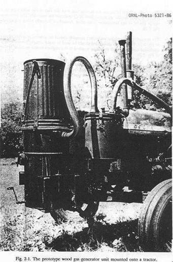
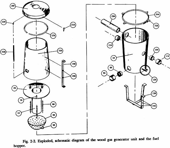
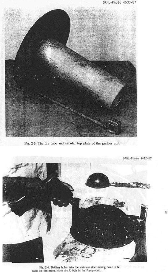
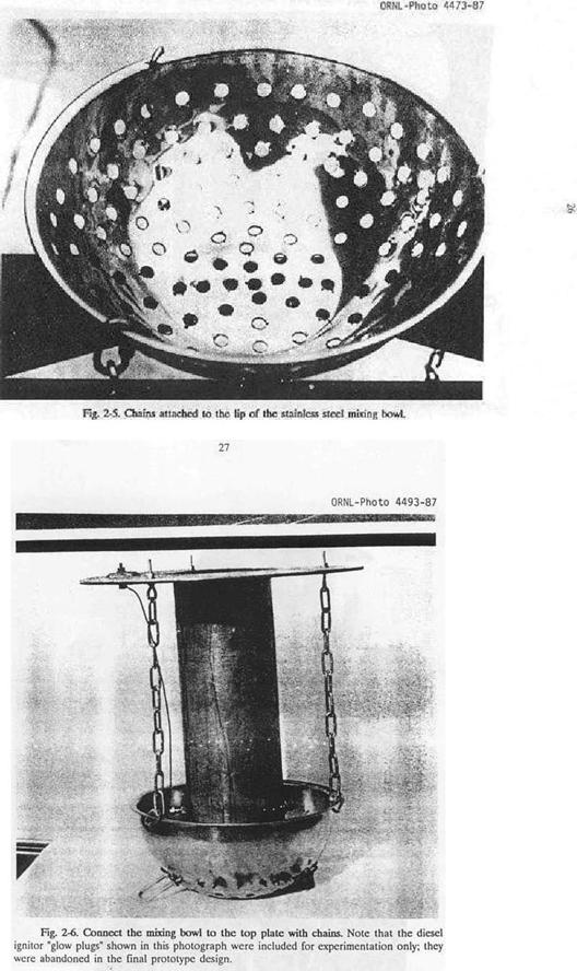
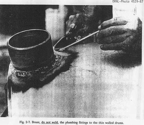
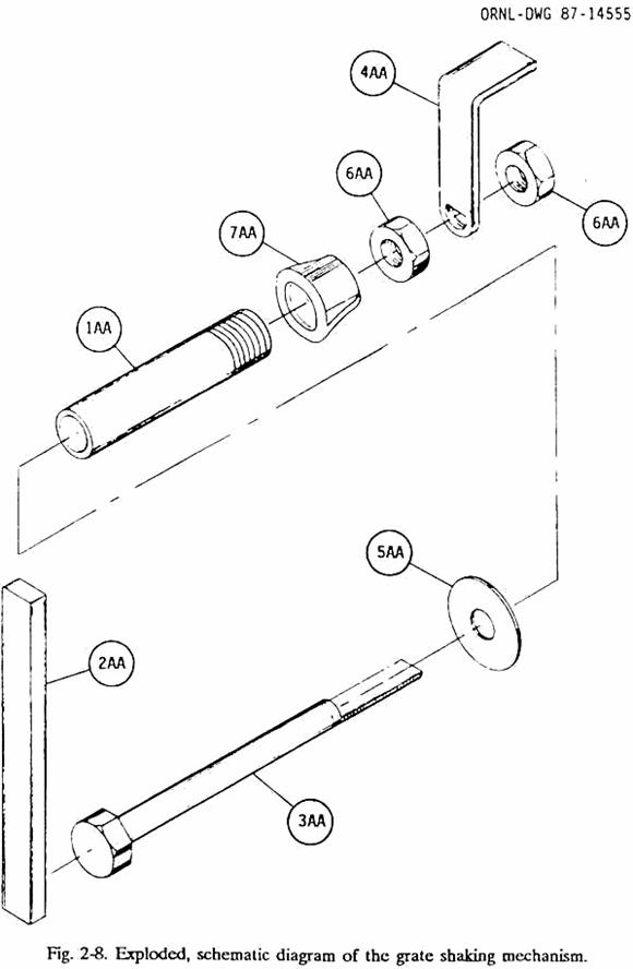
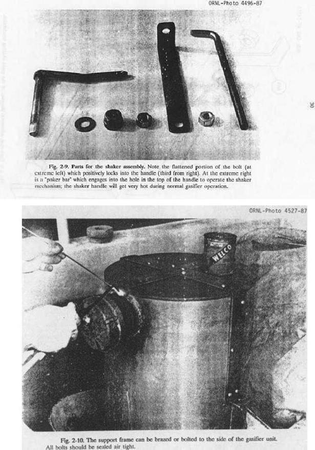
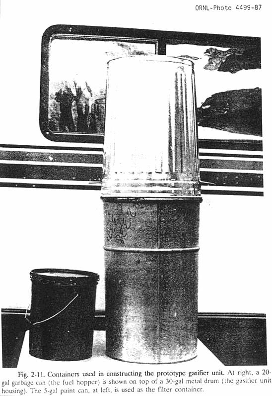
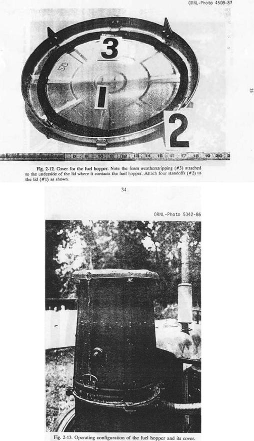
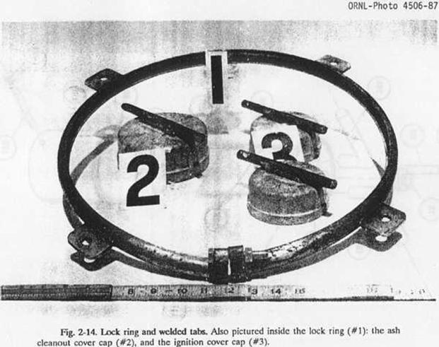
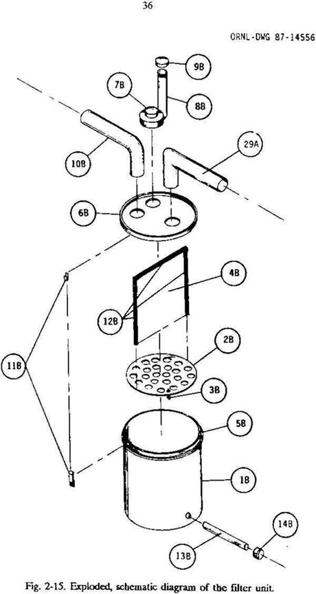
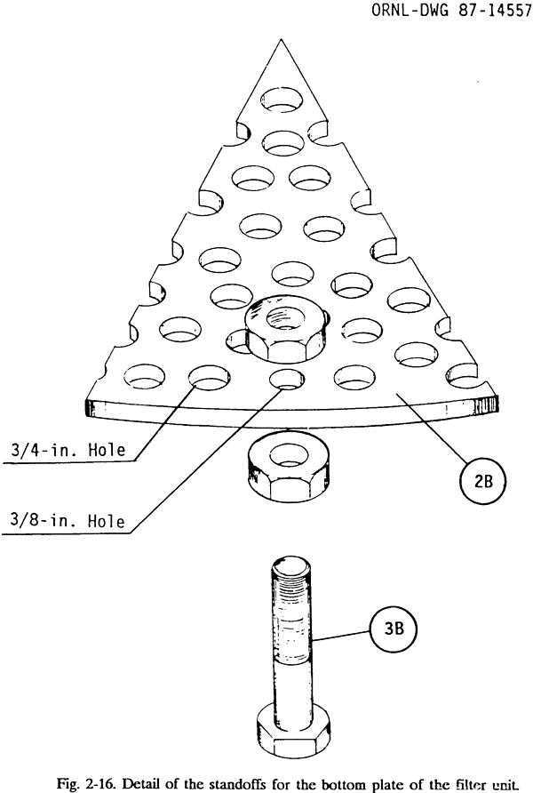
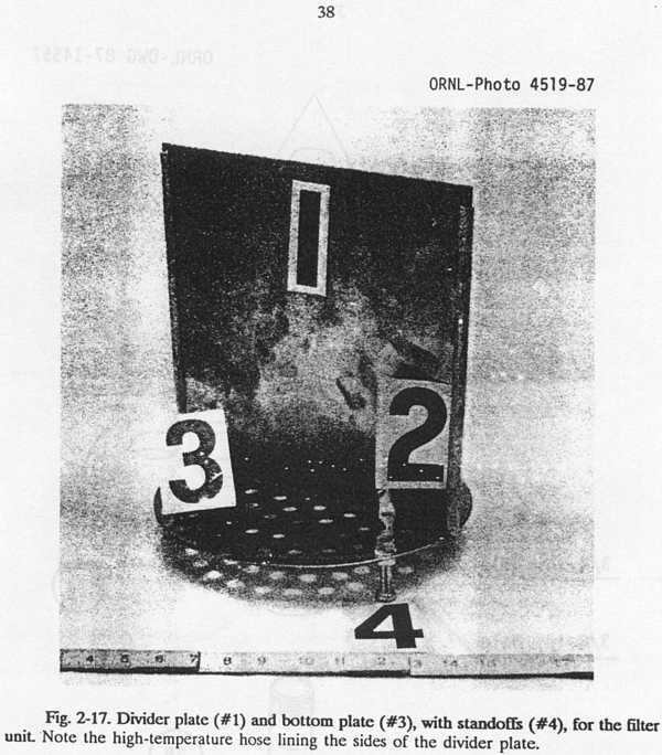
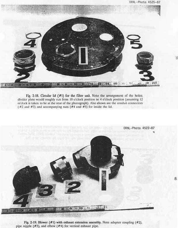
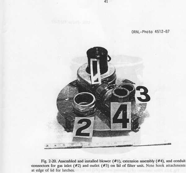

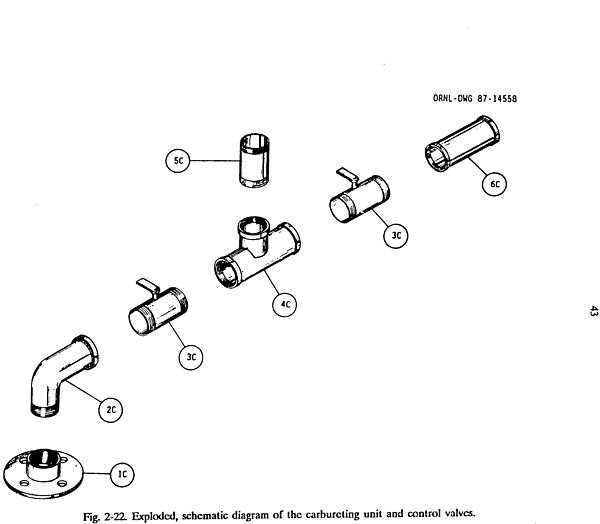
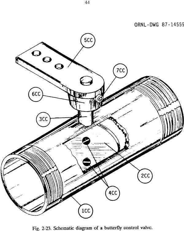
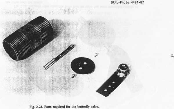
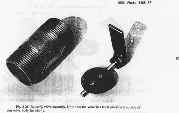
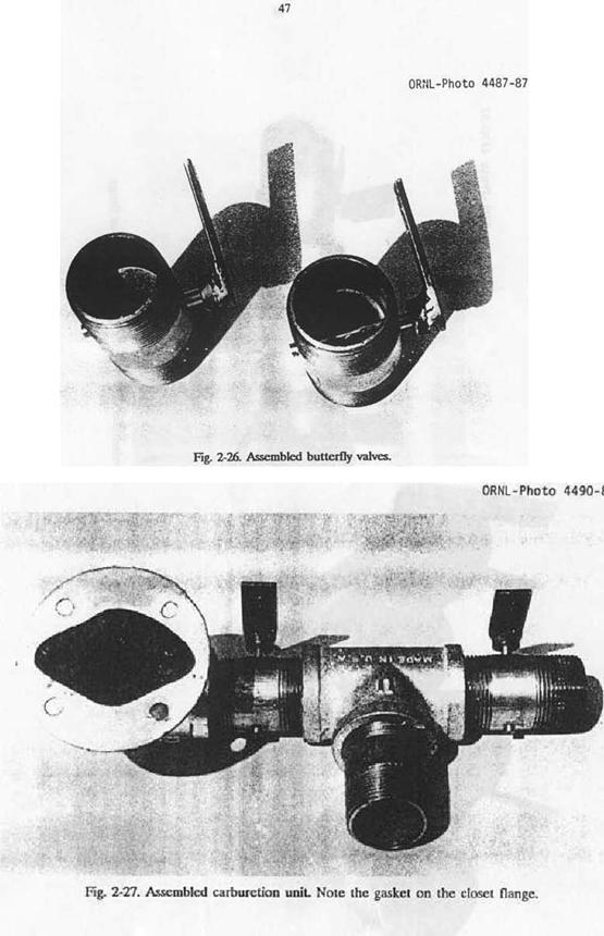
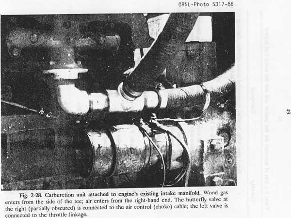
Table 2-1.
List
of materials for the gasifier unit and the wood fuel hopper.
|
Item |
Quantity |
Description |
|
1A |
1 |
Metal pipe, tube,
or other, open-ended metal cylinder; diameter and length from Table 2-2;
minimum wall thickness of 1/4 in |
|
2A |
1 |
Circular metal
plate with thickness of 1/8 in.; diameter equal to outside diameter of Item
1A |
|
3A |
1 |
30-gal metal oil
drum or metal container with approximate dimensions of 18 in. (diameter) by
29 in. (height); container must have a bottom. |
|
4A |
1 |
10-quart stainless steel mixing bowl,
container, or other stainless steel bowl with approximately
14-in. diameter and 6-in. depth |
|
5A |
1 |
2-in. metal
U-bolt. |
|
6A |
1 |
3/16-in. metal
chain with 1-in. links; 7 ft total length. |
|
7A |
3 |
1/4-in. eyebolts,
3 in. length with two nuts for each eyebolt. |
|
8A |
1 |
4-in. metal pipe
nipple. |
|
9A |
1 |
Metal pipe, cap
for Item 8A |
|
10A |
2 |
3-in. metal pipe nipple. |
|
11A |
2 |
Metal pipe cap for Item 10A |
|
12A |
|
Shaker assembly; see Fig.
2-8 : |
|
1AA |
1 |
Metal 1/2-in. pipe; 6
in. length |
|
2AA |
1 |
Iron bar stock; square
or round, 1/2 in.; 6 in. length. |
|
3AA |
1 |
1/2-in. bolt; 8 in.
long. |
|
4AA |
1 |
Iron bar stock;
rectangular, 1/4 by 1 in.; 10 in. length. |
|
5AA |
1 |
1/2-in. flat washer |
|
6AA |
2 |
1/2-in. nuts. |
|
7AA |
1 |
Metal pipe cap or
bushing for Item 1AA |
|
13A |
1 |
Iron bar stock; rectangular,
1/4 by 2 in.; 10 ft length. |
|
14A |
25 |
1/4-in. bolts; 31/4 in. length;
with nuts. |
|
15A |
1 |
20-gal metal garbage can or metal
container with approximate dimensions of 18 in. (top diameter) by 24 in.
(height); bottom is not required. |
|
16A |
1 |
Lid for 20-gal garbage can. |
|
17A |
1 |
Garden hose; 1/2 to 5/8 in. diameter;
length equal to circumference of Item 15A. |
|
18A |
1 |
Foam weather stripping with
adhesive backing; 1/4 by I in |
|
19A |
1 |
Iron bar stock; rectangular, 1/4
by 2 in.; 10 ft length. |
|
20A |
12 |
1/4-in. bolts; 3/4 in. length;
with nuts |
|
21A |
4 |
Metal triangles; 2 by 2.5 in., 1/8
to 1/4 in. thick. |
|
22A |
2 |
Metal eye hook. |
|
23A |
2 |
Screen door spring, 14 in. length. |
|
24A |
1 |
Lock ring for 30-gal (or larger)
oil drum. |
|
25A |
4 |
Metal squares; 2 by 2 in., 1/4 in.
thick. |
|
26A |
4 |
3/8-in. bolts; 3 in. length. |
|
27A |
1 |
Tube of high
temperature silicone or liquid high temperature gasket material. |
|
28A |
1 |
60-lb. sack of
hydraulic or other waterproof cement [such as SEC-PLUG (tm), which is
maunfactured by the Atlas Chemical Company, Miami, FL]. 2-in. pipe,
electrical conduit, flexible automobile exhaust pipe, or other metal |
|
29A |
1 |
Tubing; 6-ft minimum length. Pipe must be able to withstand
temperatures of 400oF |
*A fire tube with an inside diameter
of less than. 6 in. would create bridging problems with wood chips and blocks.
If the engine is rated at or below 15 horsepower, use a 6-in. minimum fire tube
diameter and create a throat restriction in the bottom of the tube
corresponding to the diameter entered in the above table.
NOTES:
For engines with displacement rated
in liters, the conversion factor is 1 liter = 61.02 cubic inches. The horsepower
listed above is the SAE net brake horsepower as measured at the rear of the
transmission with standard accessories operating. Since the figures vary when a
given engine is installed and used for different purposes, such figures are
representative rather than exact. The above horsepower ratings are given at the
engine's highest operating speed.

OPERATING AND MAINTAINING
YOUR
WOOD GAS GENERATOR
USING WOOD AS A FUEL
Because
wood was used extensively as generator fuel during World War II, and since it
is plentiful in most parts of the populated
As
a gas generator fuel, wood bas several advantages. The ash content is quite
low, only 0.5 to 2% (by weight), depending on the species and upon the presence
of bark. Wood is free of sulfur, a
contaminant that easily forms sulfuric acid which can cause corrosion damage to
both the engine and the gas generator.
Wood is easily ignited a definite virtue for the operation of any gas
generator unit.
The main disadvantages for wood as
a fuel are its bulkiness and its moisture content. As it is a relatively light material, one
cubic yard of wood produces only 500 to 600 lbs. of gas generator fuel.
Moisture content is notoriously high in wood fuels, and it must be brought
below 20% (by weight) before it can be used in a gas generator unit. By weight, the moisture in green wood runs
from 25 to 60%, in air-dried wood from 12 to 15%, and in kiln-dried wood about
8%.
Moisture
content can be measured quite easily by carefully weighing a specimen of the
wood, placing it in an oven at 220o F for thirty minutes, re-weighing the
specimen, and re-heating it until its weight decreases to a constant value. The original moisture content is equivalent
to the weight lost.
The
prototype unit in this manual (with a 6-in.-diam firetube) operated well on
both wood chips (minimum size: 3/4 by 3/4 by 1/4 in.) and blocks (up to 2-in.
cubes); see Fig. 3-1 (all figures and tables mentioned in Sect. 3 are presented
at the end of Sect. 3). Larger sizes
could be used, if the firetube diameter is increased to prevent bridging of the
individual pieces of wood; of course, a throat constriction would then have to
be added to the bottom of the firetube so as to satisfy the dimensions in Table
2-2 in Sect. 2.
SPECIAL CONSIDERATIONS
AND ENGINE MODIFICATIONS
To
start the fire in the gasifier, the blower must be used to create a suction
airflow through the wood in the hopper and downward in the firetube. If an especially high horse power engine is
to be fueled by the gasifier unit, then it might be necessary to install two
such blowers and run them simultaneously during start-up. When the wood gas leaves the gasifier unit,
all the oxygen pulled down with the air through the firetube has been
chemically converted and is contained in carbon monoxide (CO) and water (H20).
The wood gas is unable to burn without being mixed with the proper amount of
additional oxygen.
If
an air leak develops below the grate area, the hot gas will burn while
consuming the available oxygen and will create heat; this will almost certainly
destroy the gasifier unit if it is not detected soon. If an air leak develops in the filter unit or
in the connecting piping, the gas will become saturated with improper amounts
of oxygen and will become too dilute to power the engine. Therefore airtightness from the gasifier unit
to the engine is absolutely essential.
Ideally,
as the wood gas enters the engine manifold it should be mixed with air in a
ratio of
1:1
or 1.1:1 (air to gas) by volume. The
carbureting system described in this report will provide this mixture with a
minimum of friction losses in the piping.
The throttle control valve and the air control valve must be operable
from the driver's seat of the vehicle.
The engine's spark plug gaps should be adjusted to between 0.012 and
0.015 in.; the ignition timing should be adjusted to 'early.'
INITIAL START-UP
PROCEDURE
Initially, you will need to add
charcoal to the grate below the fire tube.
Subsequent operation will already have the grate full of charcoal which
has been left over from the previous operating period. Fill the fire tube with charcoal to a level 4
in. above the grate. Fill the hopper
with air-dried wood; then, proceed with the routine start-up directions
below. Charcoal produced for outdoor
barbecue grills is not well suited for gas generator use. To produce a better grade of charcoal, place
a rag soaked in alcohol on the grate, or place 3 to 5 pages of newspaper on the
grate, then fill the fire tube to a height of 10 to 12 in. with well-dried
wood. Have all the valves closed and let
the fire tube act as a chimney until the wood is converted to charcoal.
ROUTINE START-UP
PROCEDURE
1
Agitate the grate shaker handle for at least
twenty seconds to shake down the cCharcoal from the previous operating period.
2
Open the ash clean
out port and remove the ashes from the generator housing drum. Lubricate the threads
of the clean out port with high-temperature silicone, and close the cover of
the clean out port so that it is airtight.
3
Fill the hopper
with wood fuel, and tamp the fuel down lightly. Either leave the lid completely
off the fuel hopper, or adjust the opening around the lid to a 3/4-in. (or
larger) clearance.
4
Close the carburetor's air control valve and
remove the cover from the blower exhaust on top of the filter unit. Start the
blower, and let it run for thirty seconds to avoid explosion of residual gas in
the system. Then, with the blower still
operating, proceed with the next step.
5
Open the ignition port, and ignite a 12- by
12-in. piece of newspaper; with a long stick or wire, push the burning sheet of
newspaper into the grate; see Fig 3-2.
Close the ignition port. If no smoke appears at the blower's exhaust
port, repeat the start-up sequence from Step (5). If repeated attempts fail. new charcoal
should be added to the unit as described in Sect. 3.3, above, and the start-up
ignition sequence should be repeated.
6
After a few minutes of smoky exhaust, test the
gas at the, blower exhaust by safely and carefully attempting to ignite it, see
Fig. 3-3. When the gas burns consistently well, stop the blower and replace the
cover on the blower exhaust.
7
Open the carburetor's air control valve,
adjust the engine's accelerator, and start the engine in a normal manner. Let the engine warm up slowly (two to five
minutes). If the engine fails to start or dies repeatedly, restart the blower
and repeat the ignition sequence from Step (4).
DRIVING AND NORMAL
OPERATION
Shift
gears so as to keep the engine speed (rpm) high at all times. Remember that it is the vacuum created by the
pistons that provides the force which moves the gas from the gasifier unit into
the engine. Refill the hopper with wood
(as shown in Fig 3-4) before it is completely empty, but avoid refilling just
before the end of engine operation.
Periodically shake down the ashes from the grate. If your system is
equipped with a gas cooler, drain water from the cooler from time to time.
Under
operation in dry weather, the gasifier can be operated without the lid on the
fuel hopper. However, when the Gasifier
unit is shut down the hopper must be covered to prevent air from continuing to
burn the wood in the hopper. Under
wet-weather operation, the cover must be placed on the fuel hopper, and then
lifted up and rotated about 2 in. until the triangular pieces line up with the
holes in the support bars. The tension
of the screen door springs will then hold the lid closed. See Fig 3-5 for
clarification.
SHUTTING DOWN THE
GASIFIER UNIT
When
shutting down the gasifier unit, turn off the ignition switch and open the
carburetor's air control valve for ten seconds to relieve any pressure from within
the system. Then, completely close the
air control valve, and place the cover tightly on the fuel hopper. When restarting after a short stopover, let
the engine warm up briefly. After longer
stops (up to one hour), tamp down the wood lightly and try to use the blower
for restarting without relighting the wood fuel. After very long stops (over two hours) the
charcoal must be ignited again.
ROUTINE MAINTENANCE
Periodically
check all nuts on the gasifier unit, the fuel hopper, the filter unit, and the
carburetor for snugness; check all penetrations and fittings for
airtightness. In addition, perform the
following maintenance activities as scheduled:
Daily Maintenance
Open
the ash clean out port of the gasifier housing drum and remove the ashes after
shaking the grate for at least thirty seconds.
Replace the cover of the port after coating the threads with
high-temperature silicone to ensure airtightness. Open the drain tube, at the bottom of the
filter container and allow any liquid condensate to drain out; remember to
close the drain tube when finished.
Weekly Maintenance (or
every 15 hours of operation)
Clean
out the gasifier housing drum, the fuel hopper, and the filter. Rinse out the
piping and connections to and from the filter. Replace the wood chips inside
the filter, (The used wood chips from the filter can be dumped into the fuel
hopper and burned to produce wood gas.) Use high-temperature silicone on all
pipe connections and on the filter lid to ensure air tightness.
Bi-weekly Maintenance (or
every 30 hours of operation)
Make
sure that all pipe connections are secure and airtight. Check and tighten all
mounting connections to the vehicle chassis.
Check for rust on the outside of the gas generator housing drum, especially
on the lower region. Coat with
high-temperature protective paint as necessary.
OPERATING PROBLEMS AND
TROUBLE-SHOOTING
A
discussion of problems and their related causes and cures is contained in the
trouble-shooting guide of Table 3-1.
Many operational problems can be traced to failure to maintain the air
tightness of all piping connections and fittings; the piping should be
routinely checked to prevent such problems.
HAZARDS ASSOCIATED WITH
Gasifier OPERATION
Unfortunately,
gas generator operation involves certain problems, such as toxic hazards and
fire hazards. These hazards should not be treated lightly; their inclusion
here, at the end of this report, does not mean that these hazards are
unimportant. The reader should not underestimate the dangerous nature of these
hazards.
Toxic Hazards
Many
deaths in
In case of carbon monoxide
poisoning, first aid should consist of the following procedures:
1
Move the victim quickly out into the open air
or to a room with fresh air and good ventilation. All physical exertion on the
part of the victim must be avoided.
2
If the victim is unconscious, every second is
valuable. Loosen any tight clothing around the neck. If breathing has stopped,
remove foreign objects from the mouth (false teeth, chewing gum, etc.) and
immediately give artificial respiration.
3
Keep the victim
warm.
4
Always call a physician.
5
In case of mild
carbon monoxide poisoning without unconsciousness, the victim should be given
oxygen if possible.
Technical Aspects of 'Generator
Gas Poisoning'
Generator
gas poisoning is often caused by technical defects in the functioning of the
gas generator unit. When the engine is
running, independent of the starting blower, the entire system is under
negative pressure created by the engine's pistons; the risk of poisoning
through leakage is therefore minimal.
However, when the engine is shut off, formation of wood gas continues,
causing an increase of pressure inside the generator unit. This pressure increase lasts for approximately
20 minutes after the engine is shut off.
For
this reason, it is not advisable to stay in the vehicle during this
period. Also, the gas generator unit
should be allowed to cool for at least 20 minutes before the vehicle is placed
in an enclosed garage connected with living quarters. It should be emphasized that the gas formed
during the shutdown period has a carbon monoxide content of 23 to 27% and is
thus very toxic.
Fire Hazard
The outside of a gas generator housing drum may reach the same temperature as a catalytic converter on today's automobiles. Care should be taken when operating in areas where dry grass or combustible material can come into contact with the housing drum of the gas generator unit. If a gas generator unit is mounted on a personal car, bus, van or truck, a minimum 6-in. clearance must be maintained around the unit. Disposal of ashes must only be attempted after the unit has cooled down (to below 150oF). Such residue must be placed away from any combustible material and preferably be hosed down with water for absolute safety.